1W LoRa MicroMod Function Board Hookup Guide
 Nate, santaimpersonator
LoRaWAN Examples
- The example below assumes that the LoRa function board is inserted into the
0function board slot of the main board. - While there are sketch examples built into the MCCI LoRaWAN LMIC Arduino library for both the Helium and The Things Network (TTN) servers, users should use the example code that we provide below (click the Download buttons). Otherwise, users will run into various issues.
- The examples below, require a user account and device registration on whichever server you decide to utilize.
- Click here to setup an account on Helium
- Usage Cost: 1 Data Credit (1 DC = 0.001¢ in USD) per packet (up to 24 bytes)
- After a device is first added/registered to an account, it takes approx. 20 min for it to get added to the blockchain. Until then, hotspots will not recognize the device and relay its data packets.
- Click here to setup an account on The Things Stack
- The information below also assumes that users have migrated to and are currently using The Things Stack Community Edition (or V3).
- Devices registered with the V3 console will only work with gateways on the V3 console. (i.e. Data transmissions from a device registered on the V3 console will not be passed to the server, if its transmissions are only received by a gateway on registered to the V2 console.)
- When manually registering a device on The Things Stack, users will need to set the LoRaWAN version to
MAC V1.0.3(per the library specifications).
- Click here to setup an account on Helium
- We have no control over its service.
- We are not liable for any customer's choice to utilize the network.
- The cryptocurrency market valuation can be volitile.
- There may be legal and financial implications for digital wallets.
- etc.
Our example codes below, allow users to communicate with a LoRaWAN server (through a connected gateway) with the LoRa function board. Simply download, extract the file, modify the sketch to include a registered device's EUIs and application key, and then upload the code the main board with associated processor and function board.
-
Arduino IDE version: 1.8.16
- If not using the Teensy - Windows App Store version 1.8.51.0
- MCCI LoRaWAN LMIC Library version: 4.1.0
-
MicroMod Processor Boards and Arduino Cores:
Processor Board Definition RP2040 Arduino Mbed OS RP2040 Boards version: 2.5.2 ESP32 esp32 version: 2.0.0 STM32 SparkFun STM32 Boards version: 2.0.0 Artemis SparkFun Apollo3 Boards version: 2.1.1 SAMD51 SparkFun SAMD Boards (dependency Arduino SAMD Boards version 1.8.1) version: 1.8.5 - Requires - Arduino SAMD Boards (32-bit ARM Cortex-M0+) version: 1.8.11
nRF52840 [DEPRECATED - Please install standalone packages] Arduino Mbed OS Boards version: 1.3.1 Teensy Teensyduino version: 1.55
Configuring the End Device Information
Once users have registered/added an end (i.e. node) device to their user account, they will need to modify the example sketch to include their device's application EUI (APPEUI), device EUI (DEVEUI), and application key (APPKEY) (provided by the server at the end of the device registration process). Simply, replace the FILLMEIN value in { FILLMEIN }, inside of the sketch at these locations:
static const u1_t PROGMEM APPEUI[8]={ FILLMEIN };static const u1_t PROGMEM DEVEUI[8]={ FILLMEIN };static const u1_t PROGMEM APPKEY[16] = { FILLMEIN };
in this section of the sketch:
language:c
// For normal use, we require that you edit the sketch to replace FILLMEIN
// with values assigned by the TTN console.
//# warning "You must replace the values marked FILLMEIN with real values from the TTN control panel!"

// This EUI must be in little-endian format, so least-significant-byte
// first. When copying an EUI from ttnctl output, this means to reverse
// the bytes. For TTN issued EUIs the last bytes should be 0xD5, 0xB3,
// 0x70. For Helium issued EUIs the last bytes should be 0xF9, 0x81, 0x60.
static const u1_t PROGMEM APPEUI[8]={ FILLMEIN };
void os_getArtEui (u1_t* buf) { memcpy_P(buf, APPEUI, 8);}

// This should also be in little endian format, see above.
static const u1_t PROGMEM DEVEUI[8]={ FILLMEIN };
void os_getDevEui (u1_t* buf) { memcpy_P(buf, DEVEUI, 8);}

// This key should be in big endian format (or, since it is not really a
// number but a block of memory, endianness does not really apply). In
// practice, a key taken from ttnctl can be copied as-is.
static const u1_t PROGMEM APPKEY[16] = { FILLMEIN };
void os_getDevKey (u1_t* buf) {  memcpy_P(buf, APPKEY, 16);}
The format of the values should be in a hex format, as shown in the example code below. Users should doublecheck they haven't mixed up their APPEUI and DEVEUI values and that they have entered those values with the least significant byte (lsb) first. These are the most likely culprits, if users aren't seeing a join/accept response or data transmissions in the LoRaWAN server's console or the serial terminal.
language:c
// This EUI must be in little-endian format, so least-significant-byte
// first. When copying an EUI from ttnctl output, this means to reverse
// the bytes. For TTN issued EUIs the last bytes should be 0xD5, 0xB3,
// 0x70. For Helium issued EUIs the last bytes should be 0xF9, 0x81, 0x60.
static const u1_t PROGMEM APPEUI[8]={ 0x##, 0x##, 0x##, 0x##, 0x##, 0x##, 0x##, 0x## };
void os_getArtEui (u1_t* buf) { memcpy_P(buf, APPEUI, 8);}

// This should also be in little endian format, see above.
static const u1_t PROGMEM DEVEUI[8]={ 0x##, 0x##, 0x##, 0x##, 0x##, 0x##, 0x##, 0x## };
void os_getDevEui (u1_t* buf) { memcpy_P(buf, DEVEUI, 8);}

// This key should be in big endian format (or, since it is not really a
// number but a block of memory, endianness does not really apply). In
// practice, a key taken from ttnctl can be copied as-is.
static const u1_t PROGMEM APPKEY[16] = { 0x##, 0x##, 0x##, 0x##, 0x##, 0x##, 0x##, 0x##, 0x##, 0x##, 0x##, 0x##, 0x##, 0x##, 0x##, 0x## };
void os_getDevKey (u1_t* buf) {  memcpy_P(buf, APPKEY, 16);}
Once uploaded, users can open the serial monitor to view the progress of the device joining their chosen server's network and data transmissions. When using the RP2040 processor board, the example code will wait until the Serial Monitor is opened to execute the code. Users can also view the same information in the server's console, device information page.
Code Breakdown
In order to get the built-in example for the MCCI LoRaWAN LMIC library working, a few changes needed to be made. Below, is a short explanation of the modifications made to the example code that we provide (see above), to include compatibility with all the available processor boards and improve the code performance.
CS Pin Definition
The SPI library for the Arduino IDE, by default expects the chip select pin to be defined as PIN_SPI_SS. However, this pin definition is different for the ESP32 and Artemis (Apollo3) Arduino cores. Therefore, the code below was inserted to allow the code to compile for all the various processor boards.
language:c
// Redefine CS Pin Name
// SPI_CS0:     ESP32
// SS:          ESP32, nRF, RP2040
// SPI_CS:      Artemis
// PIN_SPI_SS:  STM32, SAMD51, nRF, RP2040

#ifndef PIN_SPI_SS
    // For Artemis
    #ifdef SS
        #define PIN_SPI_SS SPI_CS
    #endif // SS
    // For ESP32
    #ifdef SPI_CS0
        #define PIN_SPI_SS SS
    #endif // SPI_CS0
#endif // PIN_SPI_SS
MicroMod Pin Names
Unfortunately, for the RP2040 MicroMod processor board hasn't been included in the MbedOS Arduino core; current progress is on hold (please refer to this issue in the GitHub repository). However, with the modifications below, the RP2040 Pico board definition can be used.
By using the RP2040 Pico board definition, the generic MicroMod processor board's pin names obviously can't be used. Therefore, all the pins must be declared by their GPIO pin numbers. In addition, the default pin connections for the SPI bus on the RP2040 MicroMod processor board differs from the RP2040 Pico. To accommodate for the different pin connections, a custom SPI object was created.
language:c
// SX1276 pin connections:
//       | SLOT 0 | SLOT 1 |
//==========================
// cs    |   CS0  |   CS1  |
// dio0  |   D0   |   D1   |
// dio1  |   G2   |   G7   |
// dio2  |   G3   |   G8   |
// rst   |   G1   |   G6   |
// tx_en |  PWM0  |  PWM1  |
// rx_en |   G0   |   G5   |

#if !defined(USE_STANDARD_PINMAP)
// All pin assignments use Arduino pin numbers (e.g. what you would pass
// to digitalWrite), or LMIC_UNUSED_PIN when a pin is not connected.
    const lmic_pinmap lmic_pins = {
        #if defined(ARDUINO_RASPBERRY_PI_PICO)
            // MM RP2040 Processor Board (Using RP2040 Pico board definition)
            .nss =  21, //Chip Select
            .rxtx = LMIC_UNUSED_PIN,
            .rst =  17,
            .dio =  {6, 18, LMIC_UNUSED_PIN},
Similarly to the RP2040, the Teensy MicroMod processor board definition doesn't include the generic MicroMod processor board pin names yet (we are currently working on this update). Therefore, all the pins must be declared by their pin numbers.
language:c
#elif defined(ARDUINO_TEENSY_MICROMOD)
    // MM Teensy Processor Board
    .nss =  10, //Chip Select
    .rxtx = LMIC_UNUSED_PIN,
    .rst =  41,
    .dio =  {4, 42, LMIC_UNUSED_PIN},
RP2040 Special Consideration
As mentioned above, a custom SPI object was created. However, the custom SPI object must be passed into code execution for the RP2040 MicroMod processor board. Therefore, the setup() loop includes a modification to do this. Additionally, during our testing, the RP2040 MicroMod processor board had issues with the printouts on the serial port. Including a while() statement to wait for the serial port to be accessed by the Serial Monitor, resolved the issue.
language:c
#if defined(ARDUINO_RASPBERRY_PI_PICO)
    // Wait for serial monitor/port to open
    while (!Serial)
        ; // wait for serial port

// Pass object back into SPI
SPI = SPI_mm;
#endif // defined(ARDUINO_RASPBERRY_PI_PICO)
Helium Network Configuration
In order to improve the performance of the example code, the modifications below were made to address a clock timing issue and limit the transmission band.
language:c
// allow much more clock error than the X/1000 default. See:
// https://github.com/mcci-catena/arduino-lorawan/issues/74#issuecomment-462171974
// https://github.com/mcci-catena/arduino-lmic/commit/42da75b56#diff-16d75524a9920f5d043fe731a27cf85aL633
// the X/1000 means an error rate of 0.1%; the above issue discusses using values up to 10%.
// so, values from 10 (10% error, the most lax) to 1000 (0.1% error, the most strict) can be used.
LMIC_setClockError(1 * MAX_CLOCK_ERROR / 40);

LMIC_setLinkCheckMode(0);
LMIC_setDrTxpow(DR_SF7,14);

#if CFG_LMIC_US_like
    // This makes joins faster in the US because we don't wander all over the
    // spectrum.
    LMIC_selectSubBand(1);
#endif
Enabling the STM32 Serial Port
When uploading to the provided example code (see above) to the STM32 MicroMod processor board, users will need to enable the serial port on the processor board. Otherwise, when the Serial Monitor is opened, nothing will appear. The following settings must be used in the in the Tools drop down menu:
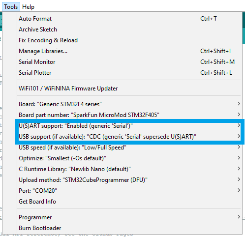
Tools drop-down menu to enable the microcontroller's serial port. (Click to enlarge)