1W LoRa MicroMod Function Board Hookup Guide
 Nate, santaimpersonator
Peer-to-Peer Example
0 function board slot of the main board.The example codes below, allow users to communicate between two LoRa function boards. Simply download, extract the files, and upload the code the main board with associated processor and function boards.
Additional examples have also been provided for users who would like to use their expLoRable (LoRa Thing Plus) board to communicate with a LoRa function board.
-
Arduino IDE version: 1.8.16
- If not using the Teensy - Windows App Store version 1.8.51.0
- RadioLib Library version: 4.6.0
-
MicroMod Processor Boards and Arduino Cores:
Processor Board Definition RP2040 Arduino Mbed OS RP2040 Boards version: 2.5.2 ESP32 esp32 version: 2.0.0 STM32 SparkFun STM32 Boards version: 2.0.0 Artemis SparkFun Apollo3 Boards version: 2.1.1 SAMD51 SparkFun SAMD Boards (dependency Arduino SAMD Boards version 1.8.1) version: 1.8.5 - Requires - Arduino SAMD Boards (32-bit ARM Cortex-M0+) version: 1.8.11
nRF52840 [DEPRECATED - Please install standalone packages] Arduino Mbed OS Boards version: 1.3.1 Teensy Teensyduino version: 1.55
Once uploaded, users can open the serial monitor to view the progress of the data transmission or reception. When using the RP2040 processor board, the example code will wait until the Serial Monitor is opened to execute the code and transmit/receive data.
Code Breakdown
In order to get the built-in example for the RadioLib library working, a few changes needed to be made. Below, is a short explanation of the modifications made to the example code that we provide (see above), to include compatibility with all the available processor boards.
CS Pin Definition
The SPI library for the Arduino IDE, by default expects the chip select pin to be defined as PIN_SPI_SS. However, this pin definition is different for the ESP32 and Artemis (Apollo3) Arduino cores. Therefore, the code below was inserted to allow the code to compile for all the various processor boards.
language:c
// Redefine CS Pin Name
// SPI_CS0:     ESP32
// SS:          ESP32, nRF, RP2040
// SPI_CS:      Artemis
// PIN_SPI_SS:  STM32, SAMD51, nRF, RP2040

#ifndef PIN_SPI_SS
    // For Artemis
    #ifdef SS
        #define PIN_SPI_SS SPI_CS
    #endif
    // For ESP32
    #ifdef SPI_CS0
        #define PIN_SPI_SS SS
    #endif
#endif
MicroMod Pin Names
Unfortunately, for the RP2040 MicroMod processor board hasn't been included in the MbedOS Arduino core; current progress is on hold (please refer to this issue in the GitHub repository). However, with the modifications below, the RP2040 Pico board definition can be used.
By using the RP2040 Pico board definition, the generic MicroMod processor board's pin names obviously can't be used. Therefore, all the pins must be declared by their GPIO pin numbers. In addition, the default pin connections for the SPI bus on the RP2040 MicroMod processor board differs from the RP2040 Pico. To accommodate for the different pin connections, a custom SPI object was created and passed into the library.
language:c
// SX1276 pin connections:
//       | SLOT 0 | SLOT 1 |
//==========================
// cs    |   CS0  |   CS1  |
// dio0  |   D0   |   D1   |
// dio1  |   G2   |   G7   |
// dio2  |   G3   |   G8   |
// rst   |   G1   |   G6   |
// tx_en |  PWM0  |  PWM1  |
// rx_en |   G0   |   G5   |

#if defined(ARDUINO_RASPBERRY_PI_PICO)
    // MM RP2040 Processor Board (Using RP2040 Pico board definition)
    int pin_cs = 21;
    int pin_dio0 = 6;
    int pin_tx_enable = 13;
    int pin_rx_enable = 16;
    int pin_nrst = 17;
    int pin_dio1 = 18;

    // Redefine SPI pins
    int miso = 20;
    int mosi = 23;
    int sck = 22;

    // Custom SPI object
    MbedSPI SPI_mm(miso, mosi, sck);

    SX1276 radio = new Module(pin_cs, pin_dio0, pin_nrst, pin_dio1, SPI_mm);

#else
Similarly to the RP2040, the Teensy MicroMod processor board definition doesn't include the generic MicroMod processor board pin names yet (we are currently working on this update). Therefore, all the pins must be declared by their pin numbers.
language:c
    #if defined(ARDUINO_TEENSY_MICROMOD)
        // MM Teensy Processor Board
        int pin_cs = 10;
        int pin_dio0 = 4;
        int pin_tx_enable = 3;
        int pin_rx_enable = 40;
        int pin_nrst = 41;
        int pin_dio1 = 42;

    #else
RP2040 Special Consideration
As mentioned above, a custom SPI object was created and passed into the library for the RP2040 MicroMod processor board. However, the library doesn't initialize the SPI bus when it is passed in. Therefore, the setup() loop includes a modification to start the SPI bus operation.
In our testing, the RP2040 MicroMod processor board had issues with the printouts on the serial port. Adding a while() statement to wait for the serial port to be accessed by the Serial Monitor, resolved the issue.
language:c
#if defined(ARDUINO_RASPBERRY_PI_PICO)
    // Wait for serial monitor/port to open
    while (!Serial){
        ; // wait for serial port
    }

    // Start SPI bus
    SPI_mm.begin();
#endif
Enabling the STM32 Serial Port
When uploading to the provided example code (see above) to the STM32 MicroMod processor board, users will need to enable the serial port on the processor board. Otherwise, when the Serial Monitor is opened, nothing will appear. The following settings must be used in the in the Tools drop down menu:
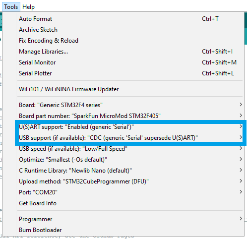
Tools drop-down menu to enable the microcontroller's serial port. (Click to enlarge)