XBee3 Thing Plus Hookup Guide
 Alex the Giant, Ell C
Experiment 2: Pulse Width Modulation (PWM)
Pulse width modulation is the technique of switching a digital signal on and off very quickly to control a variety of electrical components. By varying the amount of time a signal is on vs off, you can vary the amount of electrical power provided to a component. We can use this, for example, to dim an LED or control the speed of a motor. To learn more about PWM, see this tutorial.
In this example, we are going to create a simple LED animation that occurs as long as a button is held down.
Hardware Connections
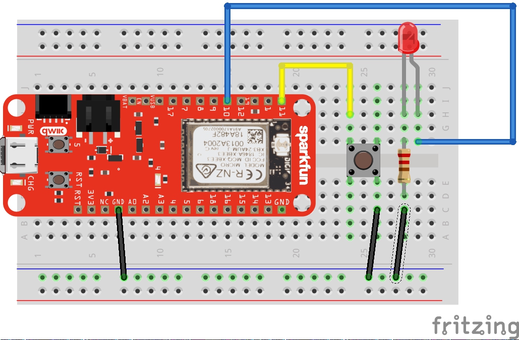
Connect an LED and a button to the XBee3 Thing Plus as per the following diagram:
Code: LED Animation
Open a new file in your favorite text editor, enter the following code:
language:python
import machine
import sys
import utime

# Pin definitions
repl_button = machine.Pin(machine.Pin.board.D5, machine.Pin.IN, machine.Pin.PULL_UP)
repl_led = machine.Pin(machine.Pin.board.D4, machine.Pin.OUT)
button = machine.Pin(machine.Pin.board.D11, machine.Pin.IN, machine.Pin.PULL_UP)
pwm_pin = machine.Pin(machine.Pin.board.D10, machine.Pin.OUT)

# Create a PWM object out of our pin object
pwm = machine.PWM(pwm_pin)

# Slowly fade LED brightness
while True:
    # If button 5 is pressed, turn on LED and drop to REPL
    if repl_button.value() == 0:
        print("Dropping to REPL")
        repl_led.value(1)
        sys.exit()

    # Increase brightness of LED if button is held
    for i in range(1024):
        if button.value() == 0:
            pwm.duty(i)
            utime.sleep_ms(2)
        else:
            pwm.duty(0)
Save your file as main.py on your local file system, overwriting your previous main.py file. Upload the code to your XBee3 Thing Plus as outlined in Experiment 1. Press RST to auto-run the new main.py file.
After the code has been uploaded and the board reset, hold down the button (the one on the breadboard that is connected to pin 11. You should see the LED slowly brighten, turn off, and then begin the brightening animation over again as long as the button is held down.
Code to Note
Much of the code should look familiar from the previous experiment, as we are creating a machine.Pin object for our LED and another one for our button. Note that we are keeping the "drop to REPL" snippet in, as we always want a way to exit out of our code's main loop.
The main difference is that we are creating machine.PWM object out of our machine.Pin object (the pin object that we've created with the pwm_pin variable. With the machine.PWM object, we can call the pwm.duty() method, which allows us to control the amount of on vs. off time on pin 11. A duty cycle of 0 means that the pin is always 0 V. A duty cycle of 511 (about half of 1023) means that pin 11 should rapidly switch between 0 V and 3.3 V equally (50%). Finally, a duty cycle of 1023 means that pin 11 should be always on (always at 3.3 V). Again, refer to the Pulse Width Modulation tutorial for more information on pwm and duty cycles.
By placing pwm.duty() inside a for loop, we can increase the brightness one stage at a time with a 2 ms delay between each stage. This ultimately gives the effect of a slowly increasing LED brightness.
Notice that we check for button 5 at the beginning of the for loop. That means that you need to hold down button 5 until the for loop (LED animation) has completed one iteration before the program realizes you've pressed the button (and should therefore exit to REPL). To help you know when you have successfully exited the program into REPL, we added repl_led.value(1) to turn on the onboard blue LED.