XBee WiFi Hookup Guide
 jimblom
 Introduction
Digi's XBee WiFi modules are a nifty, all-in-one solution to get your project connected to a wireless network and up into the \
Aside from talking over a different wireless standard, these modules work just like any XBee. You can set them up using XCTU (which also helps get it connected to a network). You can toggle I/O pins, read analog and digital inputs, and set the module to sleep. They can operate completely on their own, without the need for an external controlling microcontroller. That said, if you want to hook up an Arduino, or another processor, it can be easily done through the serial port.
You can use these modules just as you would any other XBee -- to set up a local wireless serial gateway. One XBee WiFi module can easily talk to another, as long as it has the local IP address of the other.
But these modules have another, more unique application: to make Internet-of-Things projects super-easy. Using the Etherios(TM) Device Cloud service, you can quickly get them connected to the Cloud, where they can publish data and receive commands as well.
Covered in This Tutorial
In this tutorial we'll provide a quick overview of the XBee WiFi modules. We'll then go over some examples. We'll show you how to use XCTU to connect them to a nearby wireless network -- including setting the SSID and encryption protocols.
In the last example, we'll show you how to connect the XBee WiFi up to the Device Cloud. This allows you to control the XBee through a web app loaded up in your web browser. You could control your XBee from across the sea (or from the table across your room).
Required Materials
To follow along with this tutorial, you'll need the following items:
- An XBee WiFi Module
- If you want to set up a local wireless serial gateway, you'll need more than one.
- Either a USB Explorer, Explorer Dongle, or a Serial Explorer.
- These boards exist as a "translator" between the XCTU software on your computer, and the XBee WiFi module.
- To follow along with the last example, we recommend (all of these are optional, or you might have some comparable components):
- A Breadboard
- XBee Breakout Board with headers attached
- LED (we like blue)
- Potentiometer
- SPDT Switch
- Momentary Push-Button
Suggested Reading
- Exploring XBees and XCTU -- This is a good XBee and XBee explorer primer. If anything, check out the Explorer overviews in this tutorial.
- Serial Communication -- XBees use serial to communicate and receive data. Having some basic knowledge of serial (baud rate, RX, TX, etc.) goes a long way.
- How to Use a Breadboard -- On the last page of this tutorial we'll build a circuit on a breadboard to control the XBee WiFi from the cloud.
- Logic Levels -- The maximum operating voltage of the XBee WiFi is 3.3V. Don't go attaching 5V controllers and sensors to it!
An Overview
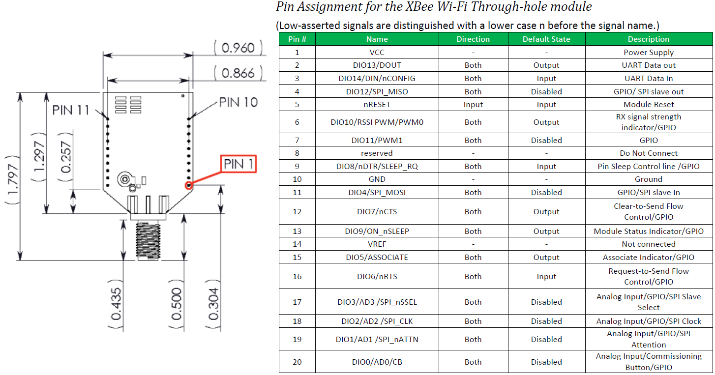
The XBee WiFi modules all share the same footprint and pinout as most "normal" XBees. They've got 20 through-hole pins, each spaced by 2mm. The pin functions range from power input to GPIO to analog input to SPI. Here, from the datasheet, is the table of pins and their function:
XBee WiFi modules can be connected to another microcontroller via their serial port, but what makes them special is they've got a whole host of I/O pins of their own. An XBee alone can toggle LEDs, or motors, or relays, and it can read digital or analog inputs as well. We'll take advantage of the XBee I/O capabilities in the To the Cloud! page, connecting LEDs and buttons directly to the little WiFi module.
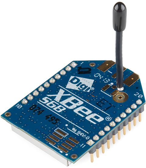
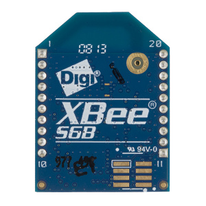
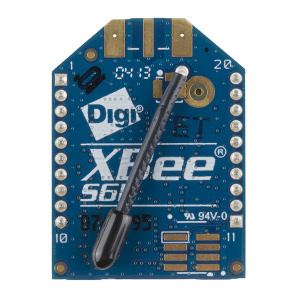
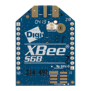
Choosing an Antenna
There are a variety of XBee WiFi modules, each with their own antenna termination. Two of the module have integrated antennas: the PCB antenna and wire (whip) antenna. These are the best choice if you're looking for cheap, but they'll also have less range.
If you need more range, consider going with the modules with a U.FL connector or an RPSMA connector. Either of these will require an compatible external 2.4GHz antenna.
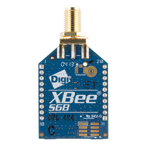
For the U.FL version, the Adhesive 2.4GHz antennas make a nice, low-profile choice. For the SMA version, duck antennas (large and regular) make a nice, stylish choice.
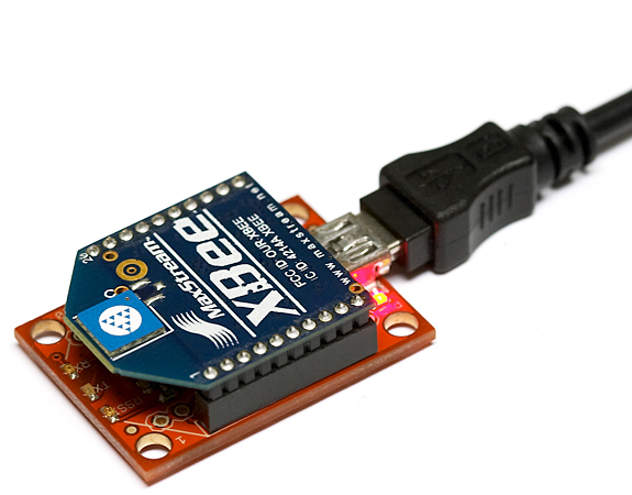
Choosing a Breakout Board
The easiest way to use these modules is to plug them into a mating breakout board. For the next pages of this tutorial, we recommend you get an XBee Explorer, which will let you communicate to the XBee from your computer. The Explorers come in mini-B USB, USB Dongle and RS-232 Serial (if you've got an ancient computer with a serial port) versions. Any of the three will work!
As alternatives to the USB and Serial explorers, there are more simple XBee breakout boards. There's the XBee Breakout Board, which simply breaks out the 2mm-spaced XBee to a more breadboard-friendly 0.1" pitch. Then there's the XBee Explorer Regulated, which breaks out the pins and has onboard voltage regulating to help mesh with the 3.3V XBee. Either of these are great for embedding into a project, but may be a little more difficult to interface with your computer.
On the next few pages we'll show you how to use the XBee WiFi with XCTU and Digi's Cloud Service. This isn't the only way to use these modules, but it's the easiest to get them up-and-running quickly. If you follow along, you can very easily have an XBee communicating with the "cloud".
Using XCTU
XCTU is Digi's XBee configuration software. It makes communicating with XBees very easy, and provides a nice interface to modify all of the module's settings. When using it with the XBee WiFi's, it even provides a WiFi network scanning and connection interface to make connecting to networks a breeze.
The current release of XCTU is available on Digi's website, unfortunately it's only available for Windows. For Mac OS X users, there is a beta version of XCTU 6.0.0 available, which we've tested and found to work flawlessly with the XBee WiFi's. (Windows users can check it out too, it's pretty slick.) Go ahead and download XCTU to follow along.
For this section we'll also assume you have an XBee connected to your computer via a USB Explorer or something similar. The Explorer should have enumerated as a COM port on your computer. This is the port we'll use to communicate with the XBee.
Connecting to a WiFi Network With XCTU
Before we can begin using the XBee WiFi, we need to set it up to connect to our WiFi network. This is a process made simple with XCTU. Follow the steps below:
- Plug your XBee into your XBee Explorer, and plug the Explorer into your computer.
- If you haven't already installed drivers for your Explorer, you may need to do so. Check out our How to Install FTDI Drivers tutorial for help there.
Open XCTU. It should open up on the "PC Settings" tab. On there, select your XBee Explorer's COM port and make sure the port settings are as below (9600 8-N-1).
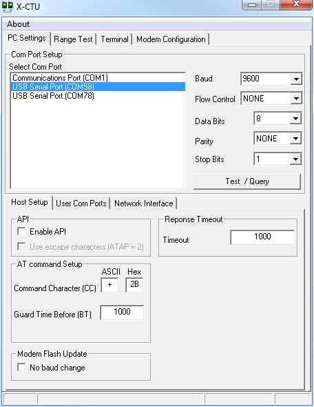 First, setup your COM port and make sure the settings are correct.
Hit Test/Query to make sure you can communicate with your XBee WiFi. You should get a response like:
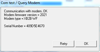 This is a good sign! Means we're communicating with the XBee.
Click over to the "Modem Configuration" tab. And click "Read" to display your XBee WiFi's stored settings.
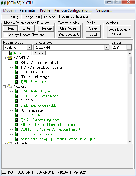 A view of the XBee WiFi's default parameters.
Select "Active Scan" near the top of the scrolling window. Then click the "Scan" button** that appears. This will open the network scan utility.
Click the "Scan" button at the bottom of the scan window. If all goes well, your network should appear above. The "Link Margin" value represents the strength of the signal (bigger is better). And the "Security" value indicates the encryption mode of the network.
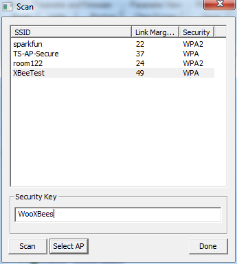 Select your network's SSID, enter a passkey if necessary, and click "Select AP".
Select your network. If it is encrypted, enter your Security Key. Then click "Select AP" (not "Done"!). XCTU will configure your XBee, and it'll try lease a DHCP address if your network is set up for it.
- This step can take a while. Be patient. Hopefully, once connected, you'll see a window telling you the XBee connected to your network in "x milliseconds".
After successfully connecting, click "Read" at the top of the window again. This will update all of the XBee's settings, including GW (the gateway IP), MK (the subnet mask), and MY (the module's assigned IP). If these values all make sense, then congratulations, your XBee is connected to your WiFi network!
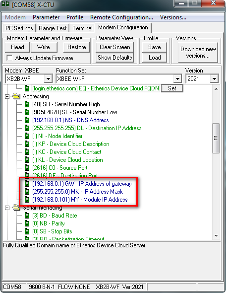 Our XBee WiFi module's IP address is 192.168.0.101.
Yay! What now? There are a few directions you can go:
Communicating with Other XBees
If you've ever used XBees before, you probably think of them as easy-to-setup wireless transceivers. Two XBees, configured correctly, can seamlessly pass data to each other from one serial port to another. XBee WiFi's are no different!
Following that same set of steps, you can set up a second XBee WiFi module to also connect to your wireless network. It'll get a unique IP address (usually assigned via DHCP). Take note of that.
To setup two XBees to communicate to each other, you'll need to modify the DL -- Destination IP Address -- of each to the other XBee. You can open a second XCTU window, or configure each one at a time.
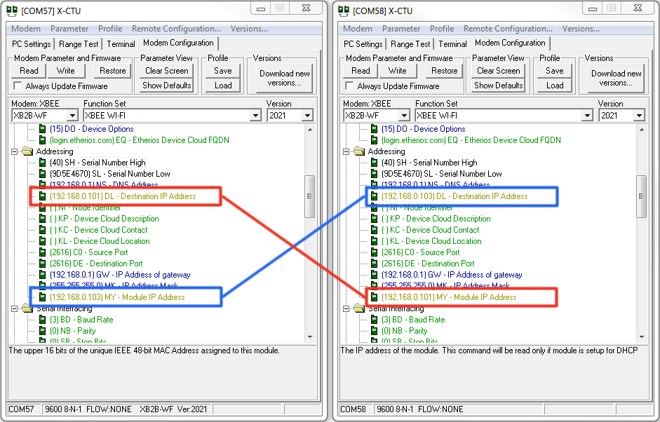
Then you can click over to the Terminal tab to type characters and have them sent from your computer, through one XBee, into the other XBee and out to a second terminal.
Another optional application for these modules is to use them on the cloud. Digi's Device Cloud service makes this very easy. Click over to the next page to see an example setup.
To the Cloud!
XBee WiFi's are built to enable simple communication with Device Cloud by Etherios (TM). The Device Cloud service allows you to interface your XBee WiFi with the web, where you can control the I/O pins and read its status from the comfy confines of your web browser (anywhere in the world!).
Now, Device Cloud is a paid service, but it's pretty reasonably priced (down to $0.50 per device per month). They also provide a free 30 day trial if you just want to try it out, which is what we'll do here.
Setting up Device Cloud
To begin, we'll need to set up the Device Cloud to communicate with our XBee WiFi. Follow the steps below to set this up:
- Go to the Device Cloud Login Page. Login or make an account if you don't already have one. If you're just looking to try it free, don't worry -- you won't have to enter any payment info.
- In Device Cloud click to the Device Management tab.
- In the Device Management section, click the Add Devices button near the top. This is where we'll point our XBee WiFi module to our Device Cloud ID.
- There are two methods for adding your XBee. We recommend the manual method:
- Make sure you're on the "Manual" half of the Add Device window.
- Find your XBee WiFi's MAC address. This is listed in XCTU under the SL and SH (serial number low and high) entries. You'll need to concatenate the two values to get your MAC address.
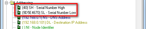 In XCTU, this is where you'll find the MAC address.
 - Set the drop down menu to MAC address. Then type your XBee's address into the text box nearby. You may need to add a couple leading 0's to make it 6-bytes long. Then click Add.
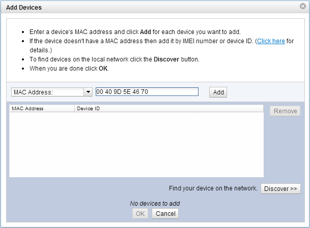
- After some thumb-twiddling your XBee and its MAC address should appear in the list below. Click OK.
- Now you should have an entry for your XBee in Device Cloud now. Right-click on the XBee and select Properties (or select the XBee and click the "Properties" button above).
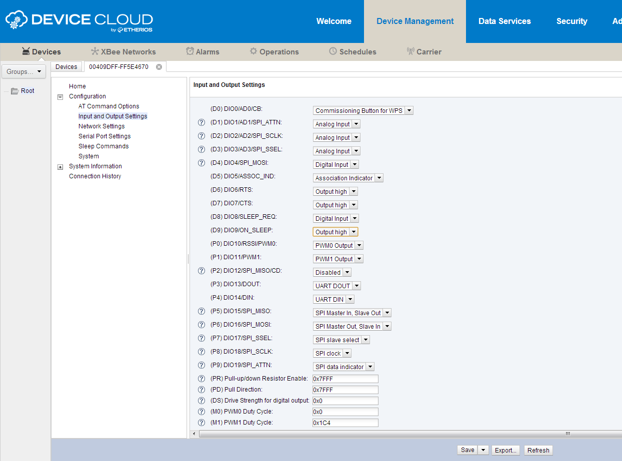
Here you can view and control just about everything as it relates to your XBee. You can set pins direction and value in the Input and Output Settings tab. Try setting a pin to "Output High", then click Save. The pins should have been driven to 3.3V, but how do you know? Time to whip a circuit together!
Take an Circuit Assembly Break!
Here's the circuit we'll use to get the most of XBee's example cloud dashboard. You don't have to hook up every part, but we recommend at least trying the LED connected to pin 13.
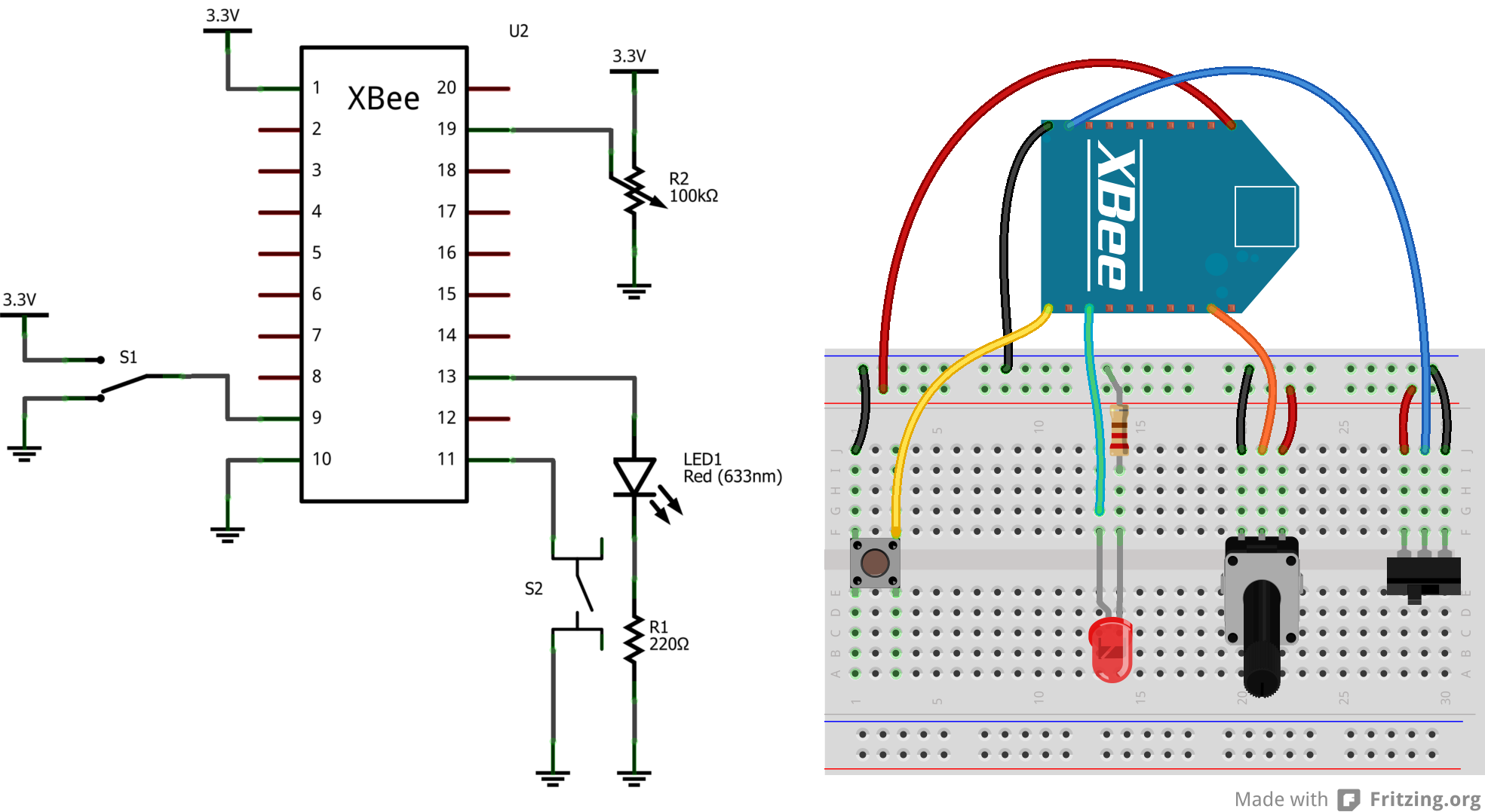
You'll still need to power the XBee WiFi module. It can remain in the XBee Explorer, or you can plug it into a separate XBee Breakout Board. Here's an image of our hookup using:
- Half Breadboard
- 10k Trimpot with Knob
- Mini Push Button
- Mini Power Switch
- 5mm Super-Bright Blue LED
- 5V/3.3V Breadboard Power Supply (set to 3.3V!)

Now that we've attached some buttons and LEDs, it's time to take it to the cloud!
Setting Up XBee Dashboard
You can use Digi's Example App to test out your Device Cloud setup. Follow these steps to get up-and-running:
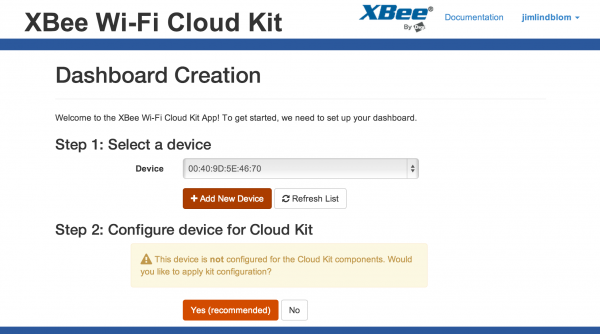
- Log in to the XBee WiFi Cloud Kit. Use the same login as the Device Cloud earlier.
- On the next page, under the "Select a Device" heading, you should see a dropdown menu with your XBee address already selected. Then just click "Yes (recommended)" to configure your XBee for this example.
- Choose a layout preset and then Create Dashboard! You should see something like this on the next screen.
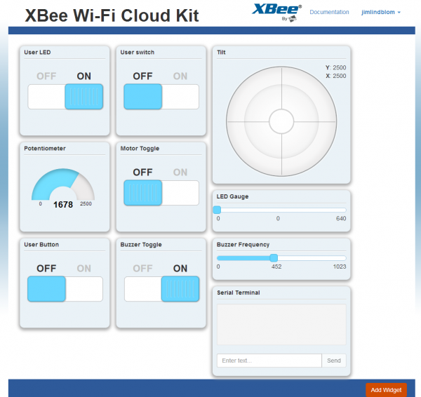

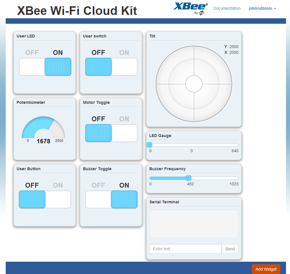
Play around with it! Try turning the LED on remotely. Then read some buttons and potentiometers. Pretty cool! Now ask a friend from across the ocean to do it. Even cooler!
If you want to build out your own app, all of the required code is viewable by clicking the </> button on a widget. It looks like everything's hosted on Digi's GitHub page, which we're huge fans of.
Resources and Going Further
Now that you've taken your XBee to the cloud, what nifty Internet-of-Things app are you going to make? If you need any help, or this tutorial didn't answer all of your question, consider checking out these resources as well:
- XBee WiFi Module Datasheet
- XBee WiFi User Manual
- XBee WiFi Development Kit Getting Started Guide
- Cloud Kit Getting Started Guide
- Cloud Kit Examples
- Mac and Windows users alike should check out the beta version of XCTU 6.0 (soon to be official?)
- Digi's XBee WiFi Cloud Kit GitHub page
Going Further
If you need some inspiration, or just want to keep reading tutorials, check these related guides out:
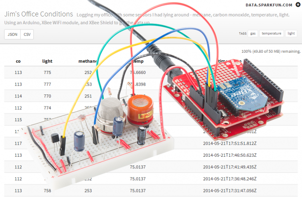
- Internet Datalogging with XBee WiFi -- The XBee WiFi doesn't have to be relegated to talking with the Device Cloud. Check out this tutorial where we combine the XBee WiFi with an XBee Shield and an Arduino to stick sensor readings on the Internet.
- ATmega128RFA1 Development Board Hookup Guide -- ATmega128RFA1 Dev Boards are like fully customizable XBees. They operate on the same standard as Zigbee (so no WiFi), but they supply you with tons and tons of I/O, and even Arduino capability.
- Bluetooth Basics -- Another wireless option, if WiFi isn't the best fit for your project, is Bluetooth. Learn all about Bluetooth in this technology tutorial.
- RN-52 Hookup Guide -- If Bluetooth is your thing, we recommend either the RN-52 for audio or the...
- BlueSMiRF Hookup Guide -- The BlueSMiRF is a fantastically easy Bluetooth module, perfect for passing low data rate serial data over the air.