ATmega128RFA1 Dev Board Hookup Guide
This Tutorial is Retired!
This tutorial covers concepts or technologies that are no longer current. It's still here for you to read and enjoy, but may not be as useful as our newest tutorials.
Overview
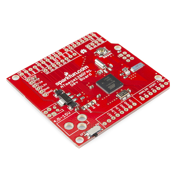
The ATmega128RFA1 is a really nifty system-on-chip, which combines an ATmega128 microcontroller with a 2.4GHz, 802.15.4 RF transceiver. It's what you might get if you smashed a wireless module, like Zigbee or Synapse, into an AVR microcontroller (like those on many Arduinos). We at SparkFun thought the chip was neat enough to warrant its own development board.
ATmega128RFA1 Development Board
DEV-11197This tutorial is focused on documenting the schematic and hardware layout of the development board. It'll also explain how to program the board via the pre-programmed serial bootloader, from the comfy confines of the Arduino IDE. We'll finish off the tutorial with some example code, detailing the basics of the ATmega128RFA1's RF communication capabilities.
ATmega128RFA1 Devlopment Board Features:
- Arduino R3 Form Factor (Arduino shield compatible)
- On-Board Chip Antenna
- 33 Digital I/O's
- SPI, TWI (I2C), and UART hardware interfaces
- 8 Analog Inputs (10-bit resolution)
- 16 MHz operating frequency
- ATmegaBOOT bootloader pre-programmed (making it programmable with an FTDI Basic and the Arduino IDE)
- On-board 3.3V regulator
- Other standard ATmega128RFA1 features:
- 6 Timers
- 128 KB Flash
- 16 KB SRAM
- 4096 Bytes EEPROM
- 2.4 GHz RF Transciever
Required Materials
In this tutorial, we'll cover the basics of getting the ATmega128RFA1 Development Board up-and-running. There will be a focus on programming the board via the bootloader (in the Arduino IDE), using an FTDI Board. To follow along, you'll need these materials:
Male headers are useful for soldering into programming headers, while female headers help to add shield compatibility. A pair of ATmega128RFA1s -- either the SparkFun board, or another development platform -- are required to test communication between the chips.
Required Tools
This assembly will require some simple soldering, so you'll need a soldering iron and a bit of solder. If you've never soldered before, check out our how to solder guide.
Suggested Reading
This tutorial assumes some previous electronics knowledge to get along. If you’re not familiar with these concepts, consider checking out our tutorials on the subject!
- What is an Arduino - While not directly using an Arduino platform, this tutorial will make use of the IDE.
- Installing FTDI Drivers - If you've never used an FTDI cable or board before, you'll need to install drivers.
- Serial Communication - We'll be using the ATmega128RFA1 boards as wireless bridges between two serial devices.
- How to Use GitHub - All of the source code and design files are hosted on Github.
About the ATmega128RFA1
The ATmega128RFA1 is a portmanteau of sorts -- two separate components combined to form one device. Half microcontroller, half RF transceiver.
ATmega128
Half of the ATmega128RFA1 is an ATmega128, an old mainstay of Atmel AVR microcontrollers. The 128 is an 8-bit microcontroller with 128kB of programmable flash, an abundance of I/O pins, an analog-to-digital converter, and much more.
Low-Power 2.4GHz Transceiver
The other half of the ATmega128RFA1 -- the "RFA1" part -- is what really makes it unique. That's because built into the chip is a 2.4GHz wireless radio transceiver. So one ATmega128RFA1 could talk to another up to about 75m away, at speeds of up to 2 Mbps.
Because it has built-in hardware support for IEEE 802.15.4, the chip can also talk to RF modules, like ZigBee's, Synapse modules, and IPv6/6LoWPAN devices. 802.15.4 defines a personal area network (PAN) of wireless devices. It's very similar to the Bluetooth standard (802.15.1) in that way. Unlike Bluetooth though, which can send data at around 3Mbps, 802.15.4 can't achieve as high a data rate, maxing out at around 250kbps. Still, 802.15.4 is an excellent, cost-sensitive choice when you don't need to quickly send huge chunks of wireless data.
In comparison to the other wireless standards and protocols out there, the ATmega128RFA1's transceiver is geared towards low-level, low-power, low-speed, low-data rate, low-range communication between devices. This isn't like WiFi, where we need to stream video, while downloading pictures of cats, and syncing our dropboxes. 802.15.4 is for sending data between embedded devices. Maybe you want to periodically transmit data from a weather station to a display in your house, or turn your coffee machine on from the bed. That's the type of situation 802.15.4 works best in! That sounds like a job for the ATmega128RFA1 Dev Board!
Schematic and Hardware
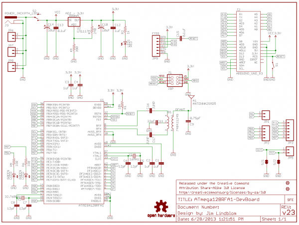
The development board surrounds the ATmega128RFA1 with all of the supporting circuitry one might need to get up-and-running with the chip.
Power Input
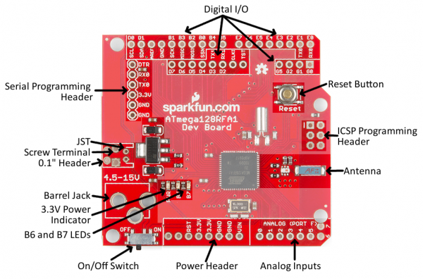
The power input section of the circuit includes a voltage regulator, which feeds 3.3V to the rest of the circuit. The following footprints are provided for power input:
- DC Barrel Jack
- JST connector (2-Pin, Right-Angle)
- 3.5mm 2-Pin Screw Terminal
- Standard 0.1"-spaced header
The slide-switch on the side of the board controls the flow of the input power sources above to the regulator.
The 3.3V and GND pins are also broken out along the side of the board. These nets are unregulated, but can be used to supply a clean, regulated 3.3V voltage source to the board.
ATmega128RFA1 Circuitry
The ATmega128RFA1 is supported by a 16MHz crystal and an assortment of decoupling caps. The RF section of the board has a crystal of its own, as well as a chip antenna and circuitry to support the RF interface. Try to avoid placing components near the antenna, as they may interfere with signal strength.
All digital I/O pins of the ATmega128RFA1 are broken out in some form or another. Two on-board LEDs are connected to the MCU's pins B6 and B7. The remaining I/O's are broken out to the outer headers of the board. The eight analog inputs on port F are available in the same place you'd expect to find an Arduino's analog pins. Key digital pins, like the hardware SPI, I2C, and UART pins, are broken out to the same locations found on Arduinos as well.
Programming Headers
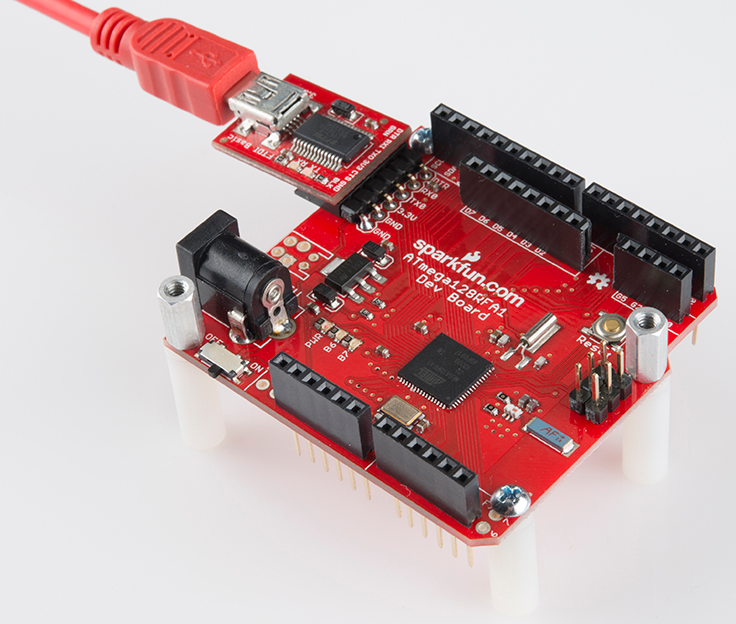
There are two programming headers on the board. One 6-pin (2x3) ICSP header, which can be used to program the chip using a standard AVR in-circuit programmer. A 6-pin serial header near the power inputs can also be used to program the chip (assuming the bootloader's still on there); this header should match up to common FTDI headers and cables (just make sure they're the 3.3V variety).
Powering the Board
There are a variety of ways to power the development board. Input jacks are broken out for barrel jack, JST, screw, and 0.1" connectors. Whichever voltage supply you choose to power the board, it should be between 4.5 and 15V. Each of these power sources is fed into the voltage regulator, which drops the voltage down to 3.3V.
If you're using the barrel jack, a 5V or 9V wall-wart is a good choice for power source.
Voltage can be fed directly to the chip, using the headers labeled "3.3V" -- just make sure the voltage doesn't exceed 3.6V. The ATmega128RFA1 can only operate at voltages between 1.8 and 3.6V.
One of the ATmega128RFA1's key features is its low power consumption. Sending or receiving RF data should only require 16 to 18mA of current. Idling, the chip should only require about 1-4.5mA. Each of the output pins can source/sink between 2-8mA.
Check out the datasheet for more electrical specs.
How To Program
Below, we'll explain the two interfaces available for programming the ATmega128RFA1. There is a serial bootloader pre-programmed onto the board, or you can use the standard AVR 6-pin ISP header. In either case, you'll probably need to solder headers onto the programming port pins to connect a programmer.
ATmegaBOOT Serial Bootloader
Bootloaders are small programs loaded onto a chip, which make uploading compiled code easier. Instead of requiring a specialized (often expensive) piece of hardware -- a programmer -- a more generalized tool can be used to upload to the board.
The ATmega128RFA1 Development Board ships with a pre-programmed serial bootloader. Either an (archaic) serial port can be used to upload code to the board, or a more common USB-to-Serial converter can be used. We recommend the 3.3V FTDI Basic board, which interfaces directly to the 6-pin serial header of the dev board.
The bootloader on the ATmega128RFA1 Dev Board is a variation of the ATmegaBOOT serial bootloader, which was used on older Arduinos like the Duemilanove. This bootloader uses the UART0 of the ATmega128RFA1, and expects uploaded code at a baud rate of 57600.
If you're familiar with avrdude, a command like the one below should upload a compiled piece of code.
avrdude -p atmega128rfa1 -c arduino -P \\.\COM## -b 57600 -D -V -U flash:w:test-sketch.hex:i
Or, skip avrdude, and use the Arduino IDE with the bootloader, as we'll explain in the following pages.
ISP Programmer
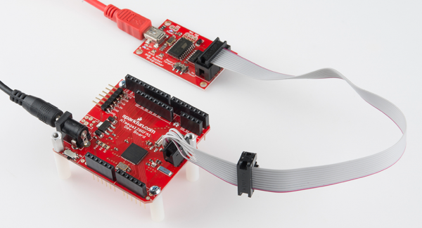
If you've got an AVR programmer and would rather skip working with the bootloader, the standard AVR 2x3 pin programming header is broken out on the board. Pin 1 of the programming port is marked with a silk-screened dash.
If you don't have an AVR programmer but would still prefer using this method for uploading code, we'd recommend the USB Pocket AVR Programmer. Using that, an avrdude command like below can be used to upload a program:
avrdude -p atmega128rfa1 -c usbtiny -P usb -D -V -U flash:w:test-sketch.hex:i
If you have an Arduino, that can work as an alternative to the AVR programmer -- check out the the ArduinoISP sketch under the examples menu.
Arduino Compatibility
Everyone loves Arduino! The simplified IDE and host of libraries and supporting code make it an awesome place to start prototyping. The ATmega128RFA1 shares a lot in common with the popular ATmega328 used on the Arduino Uno, so it seems reasonable that we should be able to program the board using the Arduino software. There are just a few extra steps which need to be taken to do so.
First, if you haven't already, download and install Arduino. Make sure you download the latest version of Arduino - 1.6.0 or higher! The addon we'll install will assume that's the version you're using.
Add the Board Definitions File
To enable the ATmega128RFA1 in your Arduino IDE, you'll need to add a board definition. Download the ATmega128RFA1 arduino addon by clicking the button below:
The "hardware" folder from that download should be added to your Arduino sketchbook. Normally the sketchbook will install to your documents/Arduino folder.
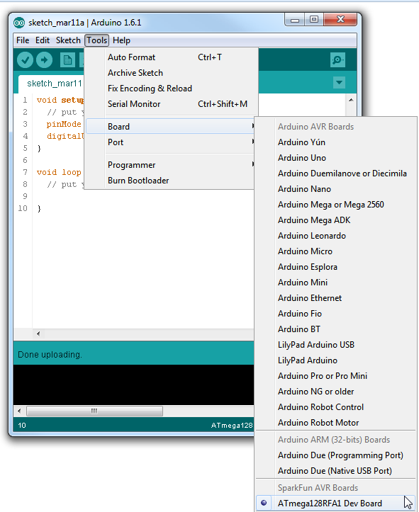
This directory contains a boards.txt file which defines the ATmega128RFA1 Dev Board, and adds a selectable option under the Tools > Board menu. When you open the Arduino IDE (close and reopen it if it's already open), this option should be added to the menu:
Pin Mapping
After you've added ATmega128RFA1-compatibility to your Arduino IDE, you can take advantage of all of the wonderful libraries you may have grown acustomed to, including Serial, SPI, and Wire. In addition to that each pin is mapped to a unique pin number, which you can invoke all of your digitalWrite, digitalRead, analogWrite, and analogRead needs upon.
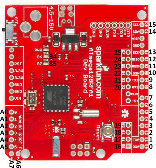
The addon defines all of the ATmega128RFA1's pins as singular numbers. Just as Arduino has pins 0-13, and A0-A6, this development board has pins 0-25, and A0-A7. Here's how the pins are mapped out:
There are a few pins with PWM functionality -- 3, 4, 5, 8, 9, 19, 34, and 35 -- which you can use for analogWrite. Note that pins 34 and 35 are not broken out to pins. They're only connected to on-board LEDs.
The SPI, UART, and I2C pins are where you'd expect them to be on an equivalent R3-or-later Arduino Uno. There is a second UART -- UART1 -- on pins D2 and D3.
Example Code
Example Sketch: RF Chat
You can download the RF chat example here (or grab it from github). This is a simple example of how to make use of the RF functionality of the ATmega128RFA1. The radio-specific functions are split off into a secondary file -- RadioFunctions.h.
You'll need two ATmega128RFA1's for this example (it's hard to demo the RF functionality without something to talk to!). They can be tied to the same computer, or a few rooms away. The maximum distance should be around 75m, but that's with complete line-of-sight, walls will diminish the range.
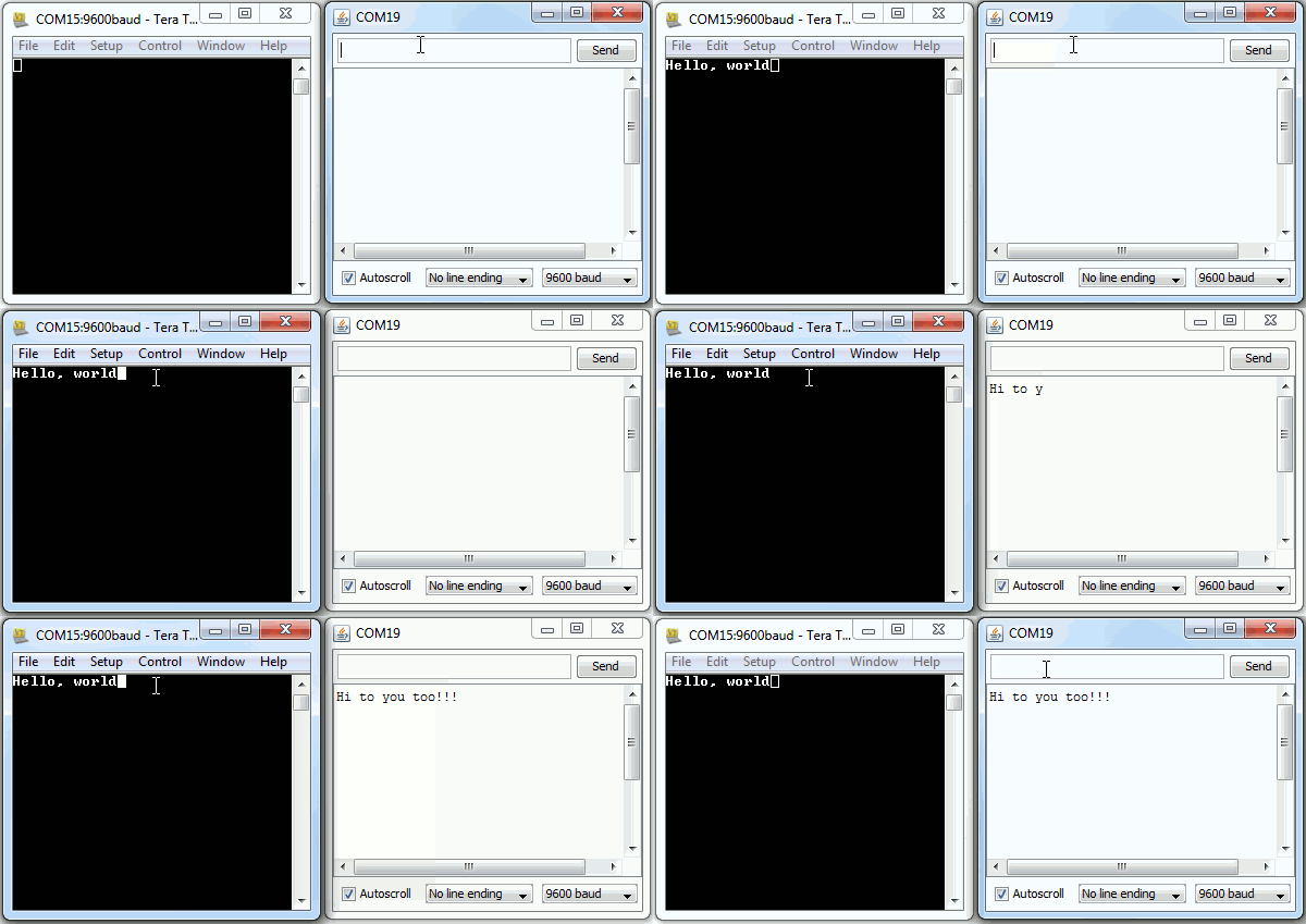
Upload the same sketch to each dev board. Then open up a serial monitor on each. You can use either the Arduino Serial Monitor, or a stand-alone terminal program (Tera Term is great for Windows users, Cool Term should work for Mac). Open up each serial port to 9600 bps (8 data bits, no parity, 1 stop bit), and start typing away! What's typed into one terminal should pop up into another.
Understanding the Sketch
There are a few key functions, and a few interrupt routines that are key to the workings of the RF transceiver.
rfBegin()
First, the radio must be initialized by calling the rfBegin() function. This is called in the setup() portion of the sketch. Check out the comments within the code for a line-by-line explanation. This function initializes the ATmega128RFA1's radio. The lone parameter for this function sets the radio's 2.4GHz channel, which should be some value between 11 and 26. Radios must be on the same channel to communicate with each other.
language:c
// Initialize the RFA1's low-power 2.4GHz transciever.
// Sets up the state machine, and gets the radio into
// the RX_ON state. Interrupts are enabled for RX
// begin and end, as well as TX end.
uint8_t rfBegin(uint8_t channel)
{
  for (int i=0; i<128; i++)
  {
    radioRXBuffer.buffer[i] = 0;
  }
  radioRXBuffer.tail = 0;
  radioRXBuffer.head = 0;

  // Setup RX/TX LEDs: These are pins B6/34 (RX) and B7/35 (TX).
  pinMode(RX_LED, OUTPUT);
  digitalWrite(RX_LED, LOW);
  pinMode(TX_LED, OUTPUT);
  digitalWrite(TX_LED, LOW);

  // Transceiver Pin Register -- TRXPR.
  // This register can be used to reset the transceiver, without
  // resetting the MCU.
  TRXPR |= (1<<TRXRST);   // TRXRST = 1 (Reset state, resets all registers)

  // Transceiver Interrupt Enable Mask - IRQ_MASK
  // This register disables/enables individual radio interrupts.
  // First, we'll disable IRQ and clear any pending IRQ's
  IRQ_MASK = 0;  // Disable all IRQs

  // Transceiver State Control Register -- TRX_STATE
  // This regiseter controls the states of the radio.
  // First, we'll set it to the TRX_OFF state.
  TRX_STATE = (TRX_STATE & 0xE0) | TRX_OFF;  // Set to TRX_OFF state
  delay(1);

  // Transceiver Status Register -- TRX_STATUS
  // This read-only register contains the present state of the radio transceiver.
  // After telling it to go to the TRX_OFF state, we'll make sure it's actually
  // there.
  if ((TRX_STATUS & 0x1F) != TRX_OFF) // Check to make sure state is correct
    return 0;    // Error, TRX isn't off

  // Transceiver Control Register 1 - TRX_CTRL_1
  // We'll use this register to turn on automatic CRC calculations.
  TRX_CTRL_1 |= (1<<TX_AUTO_CRC_ON);  // Enable automatic CRC calc.

  // Enable RX start/end and TX end interrupts
  IRQ_MASK = (1<<RX_START_EN) | (1<<RX_END_EN) | (1<<TX_END_EN);

  // Transceiver Clear Channel Assessment (CCA) -- PHY_CC_CCA
  // This register is used to set the channel. CCA_MODE should default
  // to Energy Above Threshold Mode.
  // Channel should be between 11 and 26 (2405 MHz to 2480 MHz)
  if ((channel < 11) || (channel > 26)) channel = 11;
  PHY_CC_CCA = (PHY_CC_CCA & 0xE0) | 11; // Set the channel to 11

  // Finally, we'll enter into the RX_ON state. Now waiting for radio RX's, unless
  // we go into a transmitting state.
  TRX_STATE = (TRX_STATE & 0xE0) | RX_ON; // Default to receiver

  return 1;
}
rfWrite(uint8_t b) and rfPrint(String toPrint)
These two functions are your go-to routines for sending data out of the radio. There's one function to write a single byte at a time and another to send a whole string (up to 127 characters) at once.
In the main sketch, rfPrint() is called at the very beginning to shout out to other 128RFA1 devices that the board has booted up. rfWrite() is called whenever the board sees serial data come in.
language:c
// This function sends a string of characters out of the radio.
// Given a string, it'll format a frame, and send it out.
void rfPrint(String toPrint)
{
  uint8_t frame[127];  // We'll need to turn the string into an arry
  int length = toPrint.length();  // Get the length of the string
  for (int i=0; i<length; i++)  // Fill our array with bytes in the string
  {
    frame[i] = toPrint.charAt(i);
  }

  // Transceiver State Control Register -- TRX_STATE
  // This regiseter controls the states of the radio.
  // Set to the PLL_ON state - this state begins the TX.
  TRX_STATE = (TRX_STATE & 0xE0) | PLL_ON;  // Set to TX start state
  while(!(TRX_STATUS & PLL_ON))
    ;  // Wait for PLL to lock

  digitalWrite(TX_LED, HIGH);

  // Start of frame buffer - TRXFBST
  // This is the first byte of the 128 byte frame. It should contain
  // the length of the transmission.
  TRXFBST = length + 2;
  memcpy((void *)(&TRXFBST+1), frame, length);
  // Transceiver Pin Register -- TRXPR.
  // From the PLL_ON state, setting SLPTR high will initiate the TX.
  TRXPR |= (1<<SLPTR);   // SLPTR high
  TRXPR &= ~(1<<SLPTR);  // SLPTR low

  // After sending the byte, set the radio back into the RX waiting state.
  TRX_STATE = (TRX_STATE & 0xE0) | RX_ON;
}

// This function will transmit a single byte out of the radio.
void rfWrite(uint8_t b)
{
  uint8_t length = 3;

  // Transceiver State Control Register -- TRX_STATE
  // This regiseter controls the states of the radio.
  // Set to the PLL_ON state - this state begins the TX.
  TRX_STATE = (TRX_STATE & 0xE0) | PLL_ON;  // Set to TX start state
  while(!(TRX_STATUS & PLL_ON))
    ;  // Wait for PLL to lock

  digitalWrite(TX_LED, HIGH);  // Turn on TX LED

  // Start of frame buffer - TRXFBST
  // This is the first byte of the 128 byte frame. It should contain
  // the length of the transmission.
  TRXFBST = length;
  // Now copy the byte-to-send into the address directly after TRXFBST.
  memcpy((void *)(&TRXFBST+1), &b, 1);

  // Transceiver Pin Register -- TRXPR.
  // From the PLL_ON state, setting SLPTR high will initiate the TX.
  TRXPR |= (1<<SLPTR);   // SLPTR = 1
  TRXPR &= ~(1<<SLPTR);  // SLPTR = 0  // Then bring it back low

  // After sending the byte, set the radio back into the RX waiting state.
  TRX_STATE = (TRX_STATE & 0xE0) | RX_ON;
}
rfAvailable() and rfRead()
These functions operate in a manner similar to the Arduino Serial library, if you're familiar with that. Data coming into the radio is stored in a buffer It's up to you to empty that buffer. rfAvailable() returns a number explaining how many bytes of data are still un-read in the buffer. It can be 0, meaning the buffer is empty.
rfRead() returns a single byte from the front of the receive buffer. In the main sketch loop, we continuously check if RF data is available. If there is data, we use rfRead() to collect it and print it out to the serial monitor.
language:c
// Returns how many unread bytes remain in the radio RX buffer.
// 0 means the buffer is empty. Maxes out at RF_BUFFER_SIZE.
unsigned int rfAvailable()
{
  return (unsigned int)(RF_BUFFER_SIZE + radioRXBuffer.head - radioRXBuffer.tail) % RF_BUFFER_SIZE;
}

// This function reads the oldest data in the radio RX buffer.
// If the buffer is emtpy, it'll return a 255.
char rfRead()
{
  if (radioRXBuffer.head == radioRXBuffer.tail)
  {
    return -1;
  }
  else
  {
    // Read from the buffer tail, and update the tail pointer.
    char c = radioRXBuffer.buffer[radioRXBuffer.tail];
    radioRXBuffer.tail = (unsigned int)(radioRXBuffer.tail + 1) % RF_BUFFER_SIZE;
    return c;
  }
}
Interrupt Routines
Three interrupt routines are working behind the scenes, whenever there is a radio receive or transmit. Two simple interrupt service routines (ISRs) -- the transmit end, and receieve start -- trigger the RX/TX LEDs. The receive end ISR does a lot of heavy-lifting, on the other hand. It accesses the radio's received data registers and stores the data into the shard receive buffer. None of these functions can be called manually. They all just do their job whenever called upon by the processor.
language:c
// This interrupt is called when radio TX is complete. We'll just
// use it to turn off our TX LED.
ISR(TRX24_TX_END_vect)
{
  digitalWrite(TX_LED, LOW);
}

// This interrupt is called the moment data is received by the radio.
// We'll use it to gather information about RSSI -- signal strength --
// and we'll turn on the RX LED.
ISR(TRX24_RX_START_vect)
{
  digitalWrite(RX_LED, HIGH);  // Turn receive LED on
  rssiRaw = PHY_RSSI;  // Read in the received signal strength
}

// This interrupt is called at the end of data receipt. Here we'll gather
// up the data received. And store it into a global variable. We'll
// also turn off the RX LED.
ISR(TRX24_RX_END_vect)
{
  uint8_t length;
  // Maximum transmission is 128 bytes
  uint8_t tempFrame[RF_BUFFER_SIZE];

  // The received signal must be above a certain threshold.
  if (rssiRaw & RX_CRC_VALID)
  {
    // The length of the message will be the first byte received.
    length = TST_RX_LENGTH;
    // The remaining bytes will be our received data.
    memcpy(&tempFrame[0], (void*)&TRXFBST, length);

    // Now we need to collect the frame into our receive buffer.
    //  k will be used to make sure we don't go above the length
    //  i will make sure we don't overflow our buffer.
    unsigned int k = 0;
    unsigned int i = (radioRXBuffer.head + 1) % RF_BUFFER_SIZE; // Read buffer head pos and increment;
    while ((i != radioRXBuffer.tail) && (k < length-2))
    {
      // First, we update the buffer with the first byte in the frame
      radioRXBuffer.buffer[radioRXBuffer.head] = tempFrame[k++];
      radioRXBuffer.head = i; // Update the head
      i = (i + 1) % RF_BUFFER_SIZE; // Increment i % BUFFER_SIZE
    }
  }

  digitalWrite(RX_LED, LOW);  // Turn receive LED off, and we're out
}
Those functions should serve as a backbone for all of your radio needs. Instead of setting up a chat server, you could set one outside to monitor weather conditions and relay that back to a display indoors. Or set up one under your mattress, with pressure sensors strategically connected, while another dev board connected to your coffee machine could wait for a signal to start brewing a cup. These are neat little boards, we'd love to hear about what applications you've come up with!
Resources
All of the example code, hardware layout, and Arduino addon files can be found on this project's github repo. Other resources include:
The example in this tutorial is as basic as it gets; the ATmega128RFA1 has a powerful transceiver, which can even be synced up to 802.15.4 networks (like Zigbee). Here are some other resources out there, if you're looking for something more robust:
- Lightweight Mesh - A (proprietary) Atmel Lightweight Mesh software stack.
- IEEE 802.15.4 MAC - Another Atmel-provided software stack. This one implements IEEE 802.15.4.
- BitCloud ZigBee Pro - If you're looking to make your ATmega128RFA1 communicate with ZigBee PROs, BitCloud is the software you'll need to do it. This link includes documentation and source code downloads.
- Synapse Wireless - Synapse is a nifty wireless platform, because each of the wireless modules run a python scrip and interpreter. That, along with self-healing-mesh clouds and remote procedure calls, makes Synapse totally awesome. The ATmega128RFA1 Development Board is Synapse-compatible, you can upload a Synapse hex file to it, and it'll work just like an RF200. Licenses for the Synapse software aren't free, so keep that in mind.
- ZigDuino - A really well done Arduino plug-in for the ATmega128RFA1. We're big fans.
Going Further
Now that you know how to hook up the ATmega128RFA1 Development Board, what components will you be adding with the RF transceiver to help make wireless? Need some inspiration? Check out some of these products and tutorials:
- Synapse Modules -- The Synapse RF266 in particular is based on the ATmega128RFA1. These are nifty little wireless modules, which can interpret python scripts. Check out our tutorial for working with them as well.
- XBee Modules -- With the right firmware (ZigBee), an ATmega128RFA1 could be made to communicate with these modules.
- Using the BlueSMiRF -- If your looking for easy wireless communication, Bluetooth might be for you! In this guide we explain how to set up the [BlueSMiRF](https://www.sparkfun.com/products/10269 Bluetooth modules.
Or check out some of these tutorials:
- IR Communication -- If you're only really looking to transmit data short, wireless distances, infrared may be a better/cheaper option.
- Using the OpenSegment -- The OpenSegment displays are really easy-to-use 4-digit 7-segment displays. You could use one of these displays to print messages received from other ATmega128RFA1 nodes.
Or, check out our how to use GitHub tutorial, and help us make the ATmega128RFA1 example code better by adding new features!
