ATmega128RFA1 Dev Board Hookup Guide
This Tutorial is Retired!
This tutorial covers concepts or technologies that are no longer current. It's still here for you to read and enjoy, but may not be as useful as our newest tutorials.
Overview
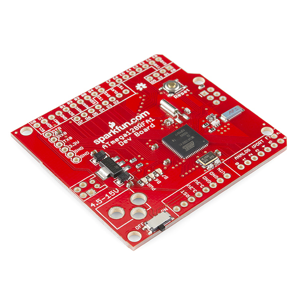
The ATmega128RFA1 is a really nifty system-on-chip, which combines an ATmega128 microcontroller with a 2.4GHz, 802.15.4 RF transceiver. It's what you might get if you smashed a wireless module, like Zigbee or Synapse, into an AVR microcontroller (like those on many Arduinos). We at SparkFun thought the chip was neat enough to warrant its own development board.
ATmega128RFA1 Development Board
DEV-11197This tutorial is focused on documenting the schematic and hardware layout of the development board. It'll also explain how to program the board via the pre-programmed serial bootloader, from the comfy confines of the Arduino IDE. We'll finish off the tutorial with some example code, detailing the basics of the ATmega128RFA1's RF communication capabilities.
ATmega128RFA1 Devlopment Board Features:
- Arduino R3 Form Factor (Arduino shield compatible)
- On-Board Chip Antenna
- 33 Digital I/O's
- SPI, TWI (I2C), and UART hardware interfaces
- 8 Analog Inputs (10-bit resolution)
- 16 MHz operating frequency
- ATmegaBOOT bootloader pre-programmed (making it programmable with an FTDI Basic and the Arduino IDE)
- On-board 3.3V regulator
- Other standard ATmega128RFA1 features:
- 6 Timers
- 128 KB Flash
- 16 KB SRAM
- 4096 Bytes EEPROM
- 2.4 GHz RF Transciever
Required Materials
In this tutorial, we'll cover the basics of getting the ATmega128RFA1 Development Board up-and-running. There will be a focus on programming the board via the bootloader (in the Arduino IDE), using an FTDI Board. To follow along, you'll need these materials:
Male headers are useful for soldering into programming headers, while female headers help to add shield compatibility. A pair of ATmega128RFA1s -- either the SparkFun board, or another development platform -- are required to test communication between the chips.
Required Tools
This assembly will require some simple soldering, so you'll need a soldering iron and a bit of solder. If you've never soldered before, check out our how to solder guide.
Suggested Reading
This tutorial assumes some previous electronics knowledge to get along. If you’re not familiar with these concepts, consider checking out our tutorials on the subject!
- What is an Arduino - While not directly using an Arduino platform, this tutorial will make use of the IDE.
- Installing FTDI Drivers - If you've never used an FTDI cable or board before, you'll need to install drivers.
- Serial Communication - We'll be using the ATmega128RFA1 boards as wireless bridges between two serial devices.
- How to Use GitHub - All of the source code and design files are hosted on Github.
