In this tutorial, we will utilize MakeCode's radio blocks to have one micro:bit transmit a signal to a receiving micro:bit on the same channel! This is useful if your weather station is installed in a location that is difficult to retrieve data from the OpenLog. We will explore a few different ways to send and receive data.
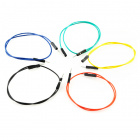
To follow along with this tutorial, you will need the following materials at a minimum. You may not need everything though depending on what you have. Add it to your cart, read through the guide, and adjust the cart as necessary.
This project tutorial builds on the experiments from the micro:climate kit. Make sure you check out the guide before proceeding.
If you aren’t familiar with the following concepts, we recommend checking out these tutorials before continuing.
To make the most out of the carrier boards with the least amount of coding, we will use the Microsoft MakeCode extensions written for the weather:bit. If you decide to add an RTC to the mix, you will need to include the gator:RTC extension as well. If you have not already, check out the instructions for installing the extensions for the board as explained in the associated guide whenever you make a new MakeCode project utilizing the boards.
To install the extension for the weather:bit, head over to our micro:climate kit experiment guide to follow the instructions.
To install the extension for the gator:RTC, head over to our gator:RTC guide to follow the instructions.
There are a few methods of transmitting data between two or more micro:bits. You can send a number or a string. If you are unfamiliar with strings, it is basically a sequence of characters that make up a word.
If you followed along with the wireless remote micro:bot, you will remember that we simply sent one number to control the robot. For the scope of this tutorial, we will be transmitting the values from more than one sensor so we will want to know what number is associated with the reading. To do that, we will send a string and number pair between two micro:bits. We will animate the LEDs for each micro:bit as an indicator.
radio code blocks? Try looking at the MakeCode reference guide!
You will need the following parts:
For a few items listed, you will need more than one unit (i.e. micro:bits, micro-B USB cables, etc.). You may not need everything though depending on what you have. Add it to your cart, read through the guide, and adjust the cart as necessary.
For this part of the experiment, we are going to send a string and number from one micro:bit to another micro:bit on the same channel.
Connect the first micro:bit to your computer via USB cable.
We are going to use Microsoft MakeCode to program the micro:bit. You can download the following example script and move the *.hex file to your micro:bit. Or use it as an example to build it from scratch in MakeCode.
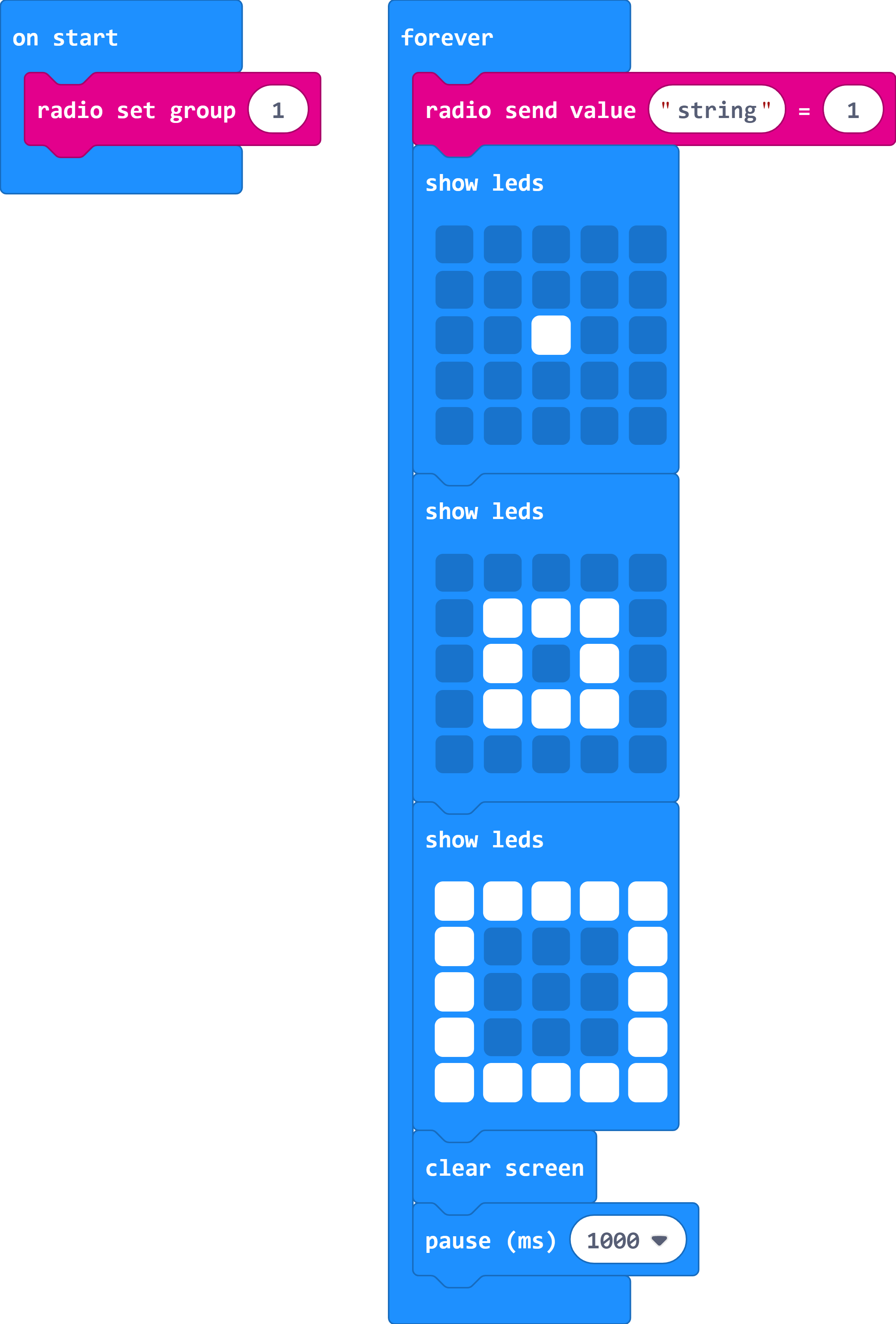
When the micro:bit is powered up, we'll want to set the radio to a certain channel. In this case, we head to the Radio blocks, grab the radio set group __ block, and set it to 1. Later (in the next experiment) we'll have the transmitting micro:bit that is attached to the weather station continuously transmit data to a receiving micro:bit. In this section, however, we'll continuously send a string and number pair out - the word string will be sent out with the number 1. For feedback, we will use the Basic blocks to have the LEDs animate with a dot expanding out into a square to represent a signal being sent out. Once the animation is finished, we will clear the screen. We will add a short delay with pause _____ from the basic blocks to give the second micro:bit some time to handle the data before sending out data again. We will set it to 1000ms.
For this part of the experiment, we are going to have a second micro:bit receive a string and number from the first micro:bit.
To avoid confusion when uploading code, unplug the first micro:bit from your computer. Then connect the second micro:bit to your computer via USB cable.
Download the following example script and move the *.hex file to your micro:bit. Or use it as an example to build it from scratch in MakeCode. You will need to open a new project to receive the data from the first part of this experiment.
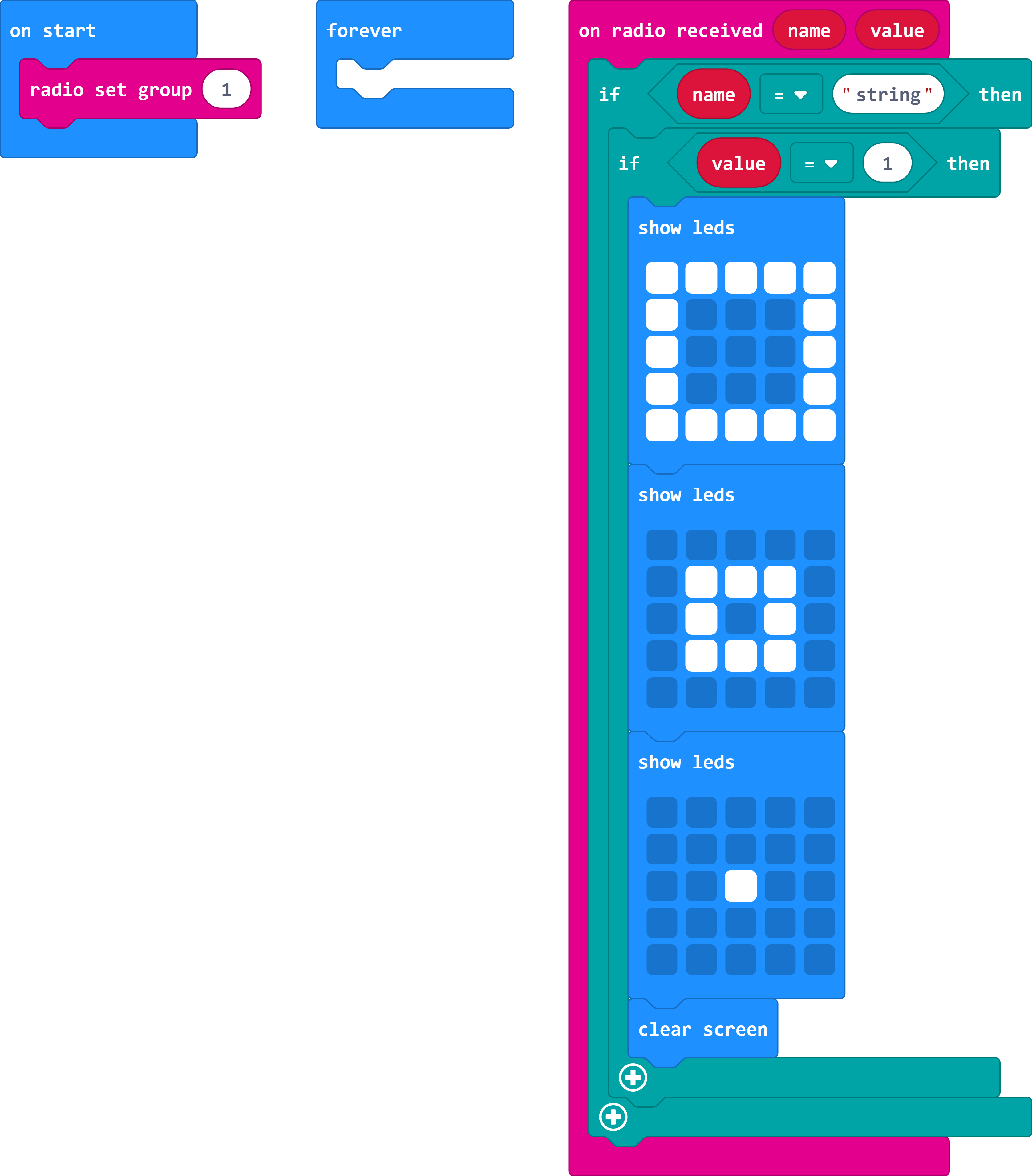
When the second micro:bit is powered up, we'll want to set the radio to the same channel as the first micro:bit. In this case, it will be 1. Using the on radio received name value block, we will want to check to see what signal was sent from the first micro:bit. In this case, we will want to check to see if the string that was received and stored in name is what we expect. Using the if statement from the Logic blocks, we will want to check to see if name matches word string by using the "_" = "_" block. If it matches, we will want to see if the value matches 1 by using the ___=___. Note the differences in the two comparisons. One compares a string while the other compares a number.
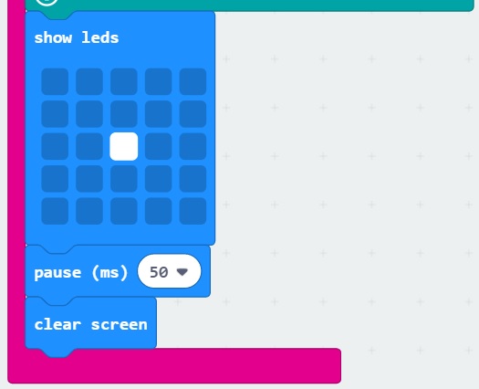
If both match, we will want some sort of indicator. Visually, using LEDs would be the easiest so an animation of a square shrinking to a dot was chosen to represent the received signal. Once the animation is finished, we will want to clear the screen until we receive another signal.
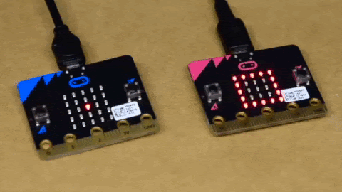
Powering both micro:bits up, the first micro:bit (our transmitting) will send a string and number pair out on channel 1. In this case, the pair was string and 1, respectively.
The second micro:bit (our receiving) will take that string and number pair that was sent on channel 1 and do something based on the condition statement. In this case, there is an animation using the LED array to indicate when we have received the pair.
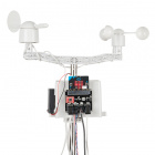
Remember our weather station from the micro:climate kit? If you have been following along from the last experiment, we were logging sensor data to an OpenLog and saving it to a microSD card to graph. Now what if you installed the weather station in a remote location where it was difficult to obtain the sensor readings? In this part of the experiment, we will have one micro:bit transmit sensor readings from the weather:bit and weather meter. Then in the second part of this experiment, we will take the readings and output them to a serial terminal.
You will need the following parts:
For a few items listed, you will need more than one unit (i.e. micro:bits, micro-B USB cables, etc.). You may not need everything though depending on what you have. Add it to your cart, read through the guide, and adjust the cart as necessary.
For this part of the experiment, we are going to send a string and number pair for each sensor attached to the first micro:bit. A second micro:bit on the same channel will receive the data and output it to a serial terminal.
We will also assume that your weather meter has been assembled. Make sure to check out following guides before continuing on.
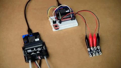
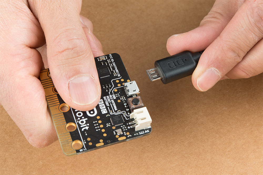
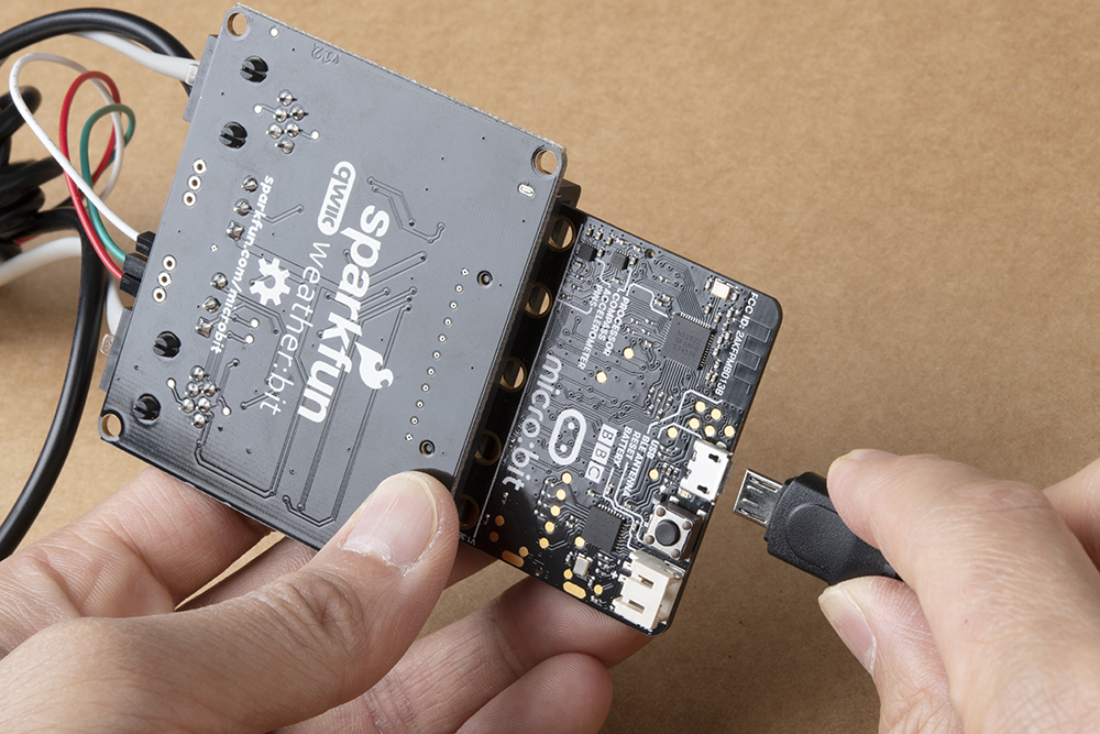
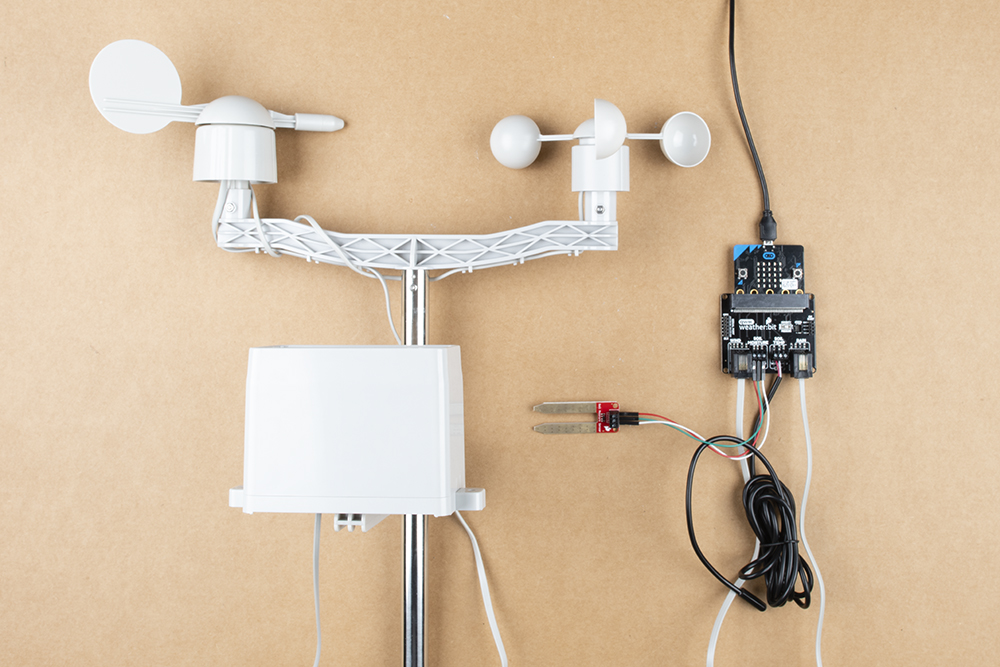
If you have not already, insert one micro:bit into the weather:bit's carrier board. Make sure to insert the micro:bit with the LED array facing up (the same direction the connectors) as explained in the micro:climate kit experiment guide. We’re continuing on from experiment 7. Below is a view from the back as a USB cable is being inserted.
Your setup should look similar to the image below.
We are going to use Microsoft MakeCode to program the micro:bit. You can download the following example script and move the *.hex file to your micro:bit. Or use it as an example to build it from scratch in MakeCode.
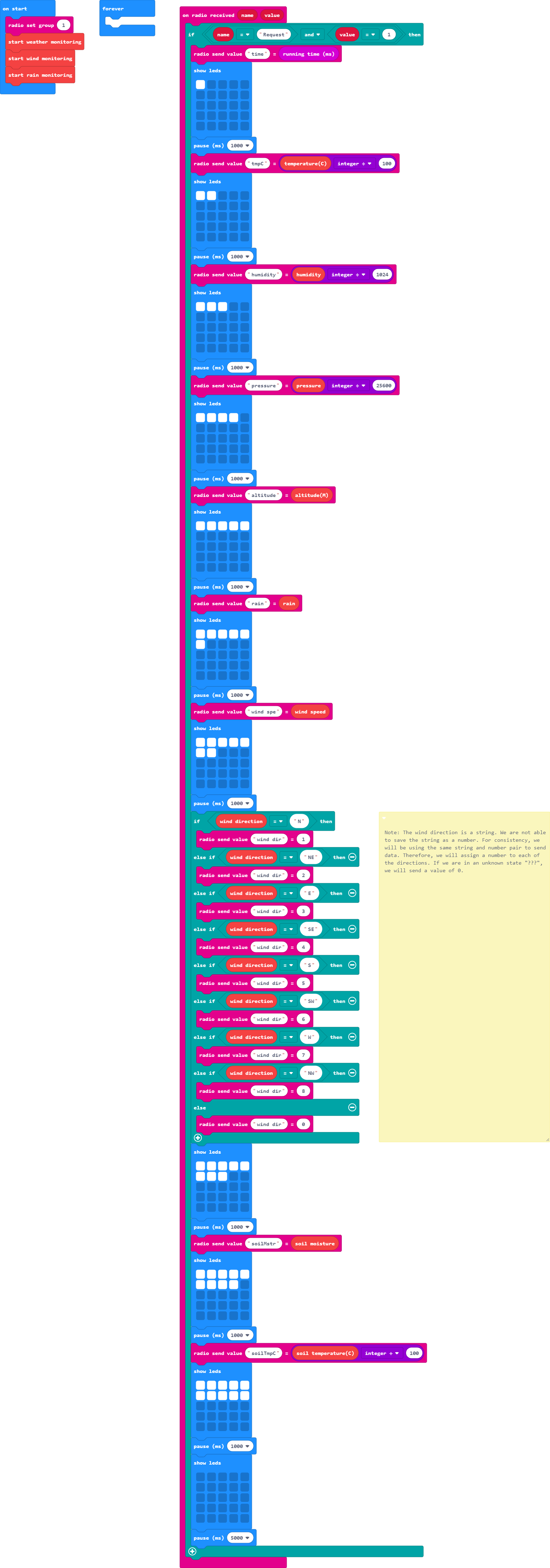
In the on start block, we will set up the channel to 1 just like the previous example. Additionally, we will set up the weather, wind, and rain blocks just like each of the experiments in the micro:climate kit experiment guide.
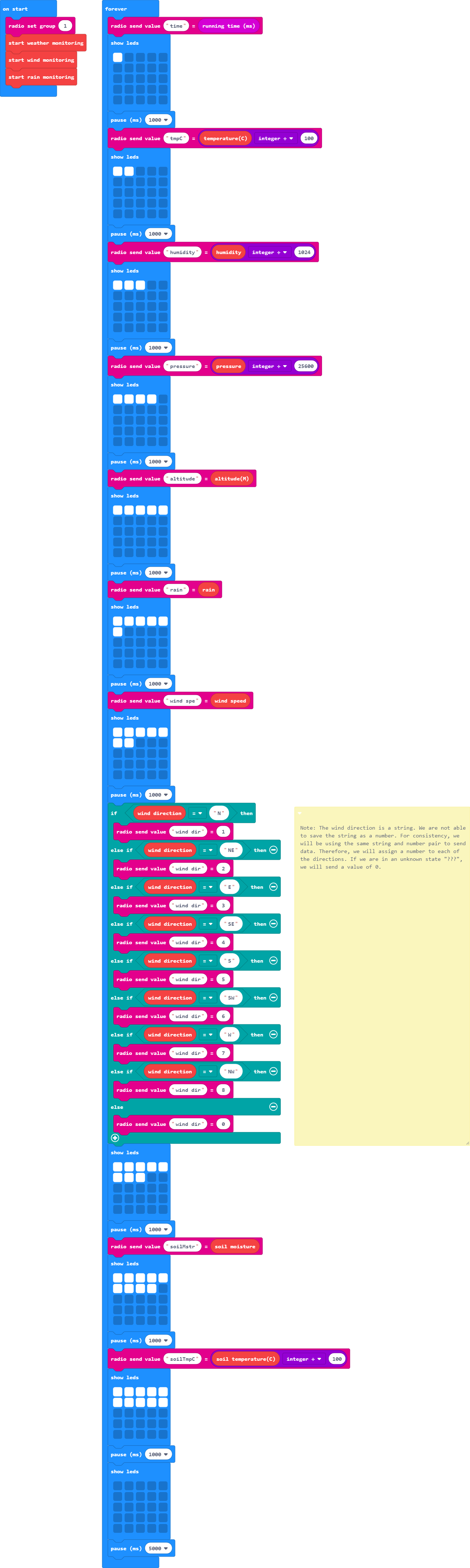
In the forever loop, we will send a string and number for each reading with the values calculated every second. For each piece of data, we will update the LED array to indicate the status. The following blocks of code were taken from the basic, radio, weather, and logic blocks.
timetmpChumiditypressurealtituderainwind spewind dirsoilMstrsoilTmpCIf you look at each string, you will notice a few of the names were shortened. This is due the radio block only being able to send 8x characters for each string and number pair. Additionally, since the wind direction is a character and not a number, we will need to assign a number to refer to each wind direction. If the wind vane is pointing to an unknown direction, we will output ???. If you remember from the troublehsooting tip in experiment 5, this may be due to a loose connection or when the micro:bit read the wind vane at a certain moment when the magnet was within a small region somewhere between the 8x directions.
When finished, we will clear the screen and wait a few seconds using the pause_____ block to give the second micro:bit some time to finish what it was doing before we start sending more data. This value can be adjusted to send out data at longer intervals.
For this part of the experiment, we are going to have a second micro:bit receive a string and number pair for each sensor that was sent from the first micro:bit. We will then view the sensor data using a serial terminal. In this case, we will use the MakeCode console. You can use a different serial terminal program depending on your personal preference.
To avoid confusion when uploading code, unplug the first micro:bit from your computer. Then connect the second micro:bit to your computer via USB cable.
Download the following example script and move the *.hex file to your micro:bit. Or use it as an example to build it from scratch in MakeCode. You will need to open a new project to receive the data from the first part of this experiment.
When the code first starts, we initialize a serial output on the micro:bit to send serial to the USB with the help of the serial blocks. Using the serial redirect to USB code block defaults the 115200 baud. This is useful whenever we need to inspect the sensor readings and interpret the values in a serial terminal.
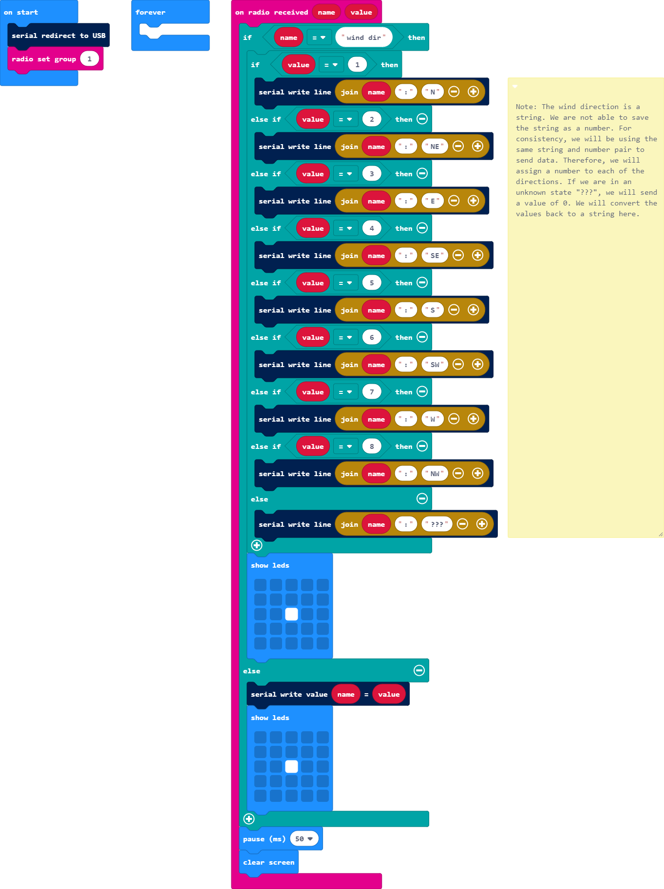
For every string and number pair that we receive, we will output it to the serial terminal. If we receive a number for the wind direction, we will translate it back to its respective direction. For feedback, we will use the LED array as a status indicator on the receiving end. Every time we receive data, we will blink the center LED in the array before clearing it.
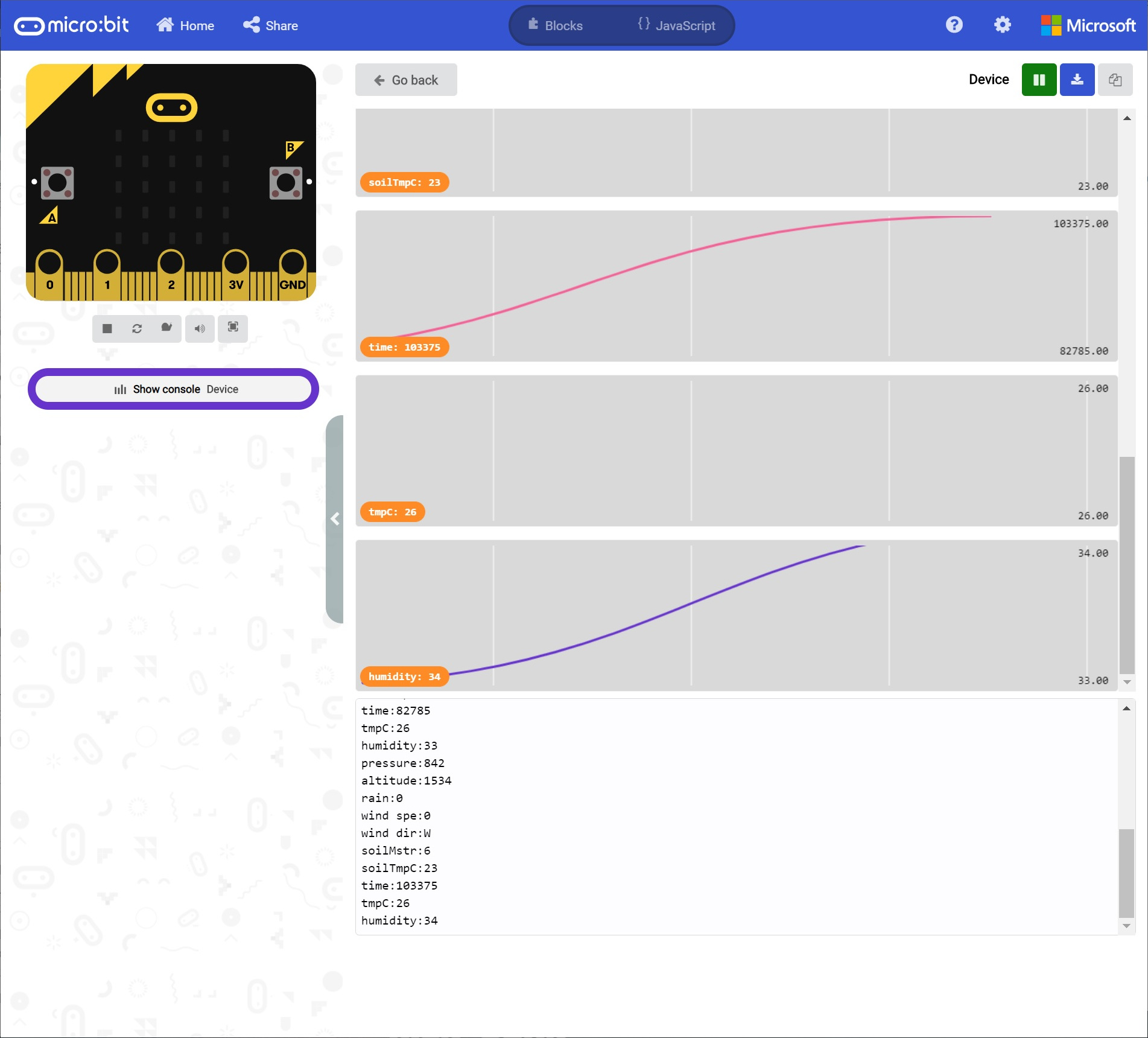
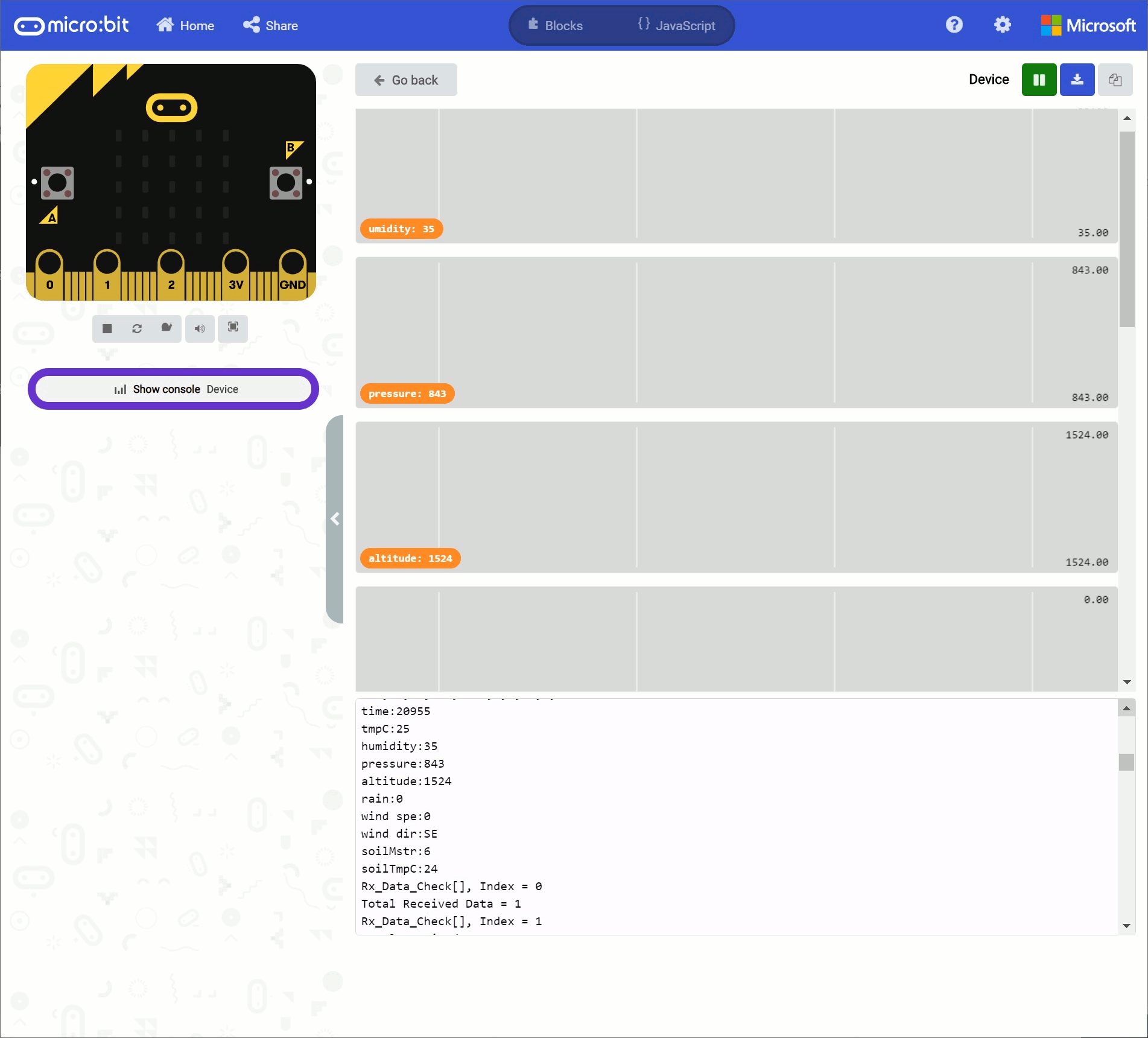
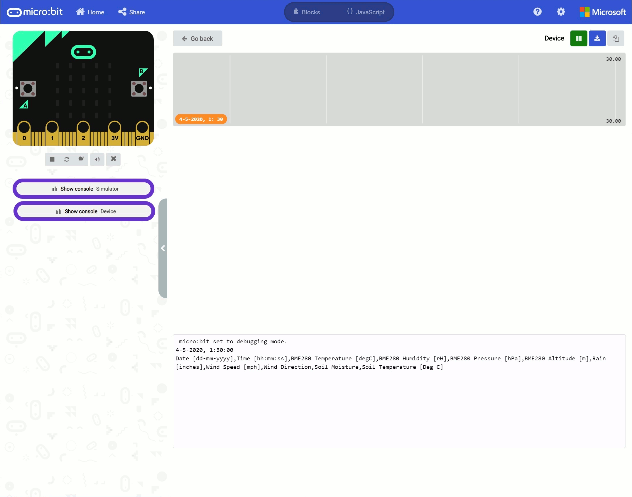
For the scope of this tutorial, we'll use the MakeCode console to display the serial output. If you have paired the micro:bit to your computer and used the one-click download feature for MakeCode, a "Show console Device" button should appear in MakeCode. Click on the button to begin viewing the serial output. A graph and serial monitor will appear over the MakeCode code editor. Otherwise, open a serial terminal with 115200 baud and connect to the COM port listed for the micro:bit.
At this point, apply power to the first micro:bit that is attached to the weather station. It will begin transmitting sensor data to the second micro:bit and display in the MakeCode console. You may notice that some data may not be graphed if it is not changing. This is due to the graph automatically resizing. Try testing the sensors to see if the values change as expected!
We have successfully sent data from the first micro:bit and received it using a second micro:bit! However, we are not done yet! If you look at the data sent, sometimes the second micro:bit can miss some data points depending on when either micro:bit is powered up. If you are just viewing the data on the serial terminal or saving the values into a variable, it's not too much of a concern. However, this will cause problems if you decide you want to save and graph the data using the OpenLog. The data may be shifted depending on when you powered the micro:bit. The missing data points will have holes in your data set and cause errors whenever the micro:bit saves data intended for a different sensor. Below is an example output with missing data.

In this section, we will save the weather stations running time and temperature into an array. To check, we will have a second array to keep track of what is received to ensure that we have received everything that was transmitted. If we have received it, we will display the values in comma delimited form through a serial terminal. If not, we will not output the values. For debugging purposes and to help us understand what is going on, we will also display the status of the second array that is keeping track of what is being received.

You will need the following parts:
For a few items listed, you will need more than one unit (i.e. micro:bits, micro-B USB cables, etc.). You may not need everything though depending on what you have. Add it to your cart, read through the guide, and adjust the cart as necessary.
Let's take a step back and only send the running time and temperature for simplicity.
We recommend having just the weather station's micro:bit connected for this section to avoid confusion when uploading code.
The setup is the same as the previous experiment. However, we are just using the BME280's temperature sensor. We can leave everything connected as it currently is from the previous example.
We are going to use Microsoft MakeCode to program the micro:bit. You can download the following example script and move the *.hex file to your micro:bit. Or use it as an example to build it from scratch in MakeCode.
This code is just a shortened version of experiment 2.1's code for simplicity.

In this section, we will be receiving two readings and storing them into arrays. We will check the data to see if we received all the readings for that instance. If we do not receive everything in that row, we will not output the readings to the serial terminal. Instead we will output a message indicating that we did not receive everything.
To avoid confusion when uploading code, unplug the first micro:bit from your computer. Then connect the second micro:bit to your computer via USB cable.
We are going to use Microsoft MakeCode to program the micro:bit. You can download the following example script and move the *.hex file to your micro:bit. Or use it as an example to build it from scratch in MakeCode.
There is a lot going on. Let's inspect the code in parts.
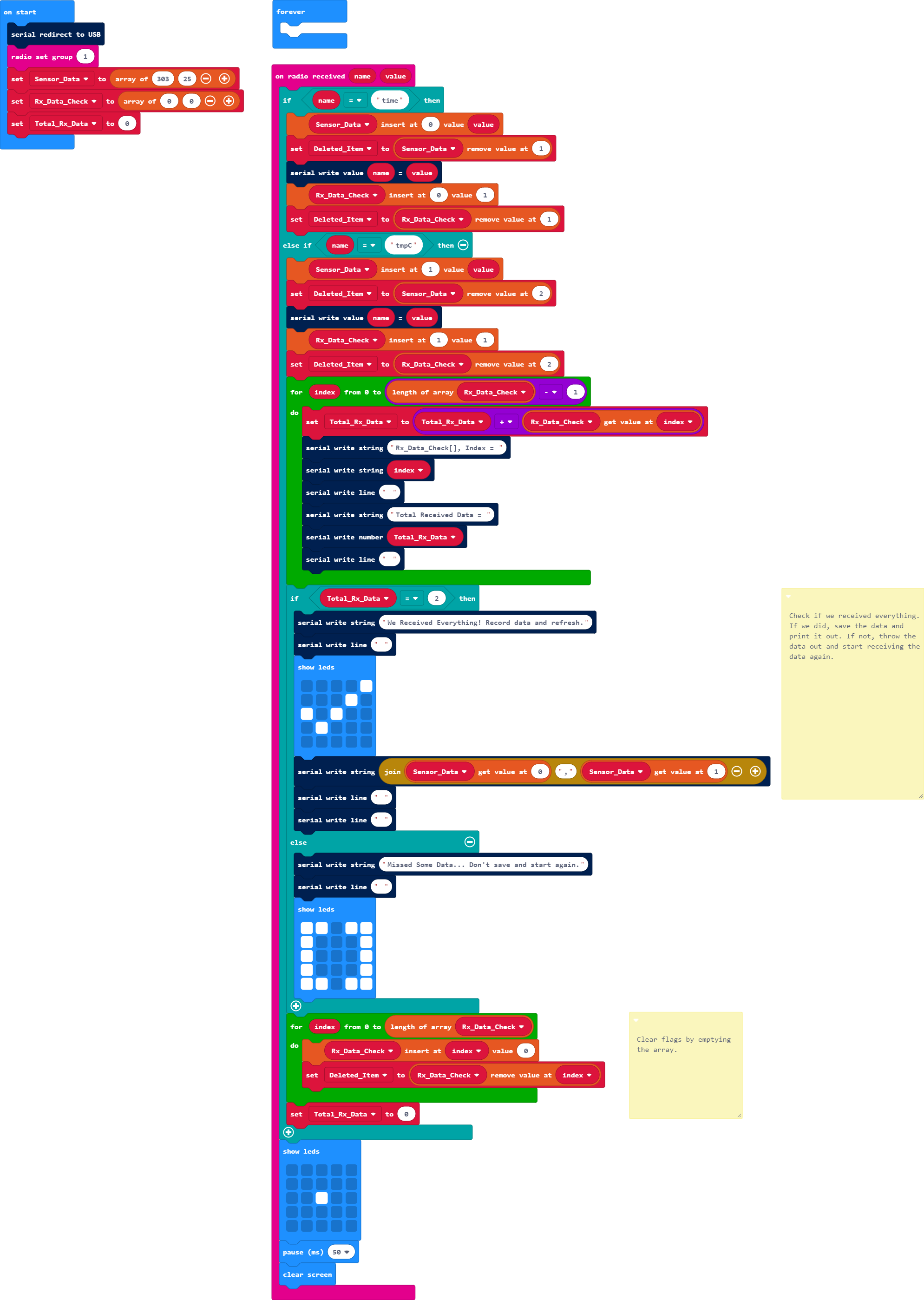
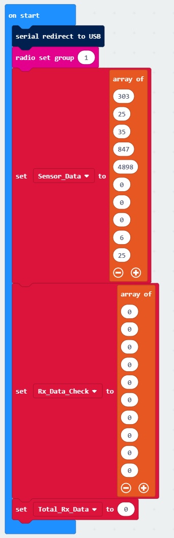
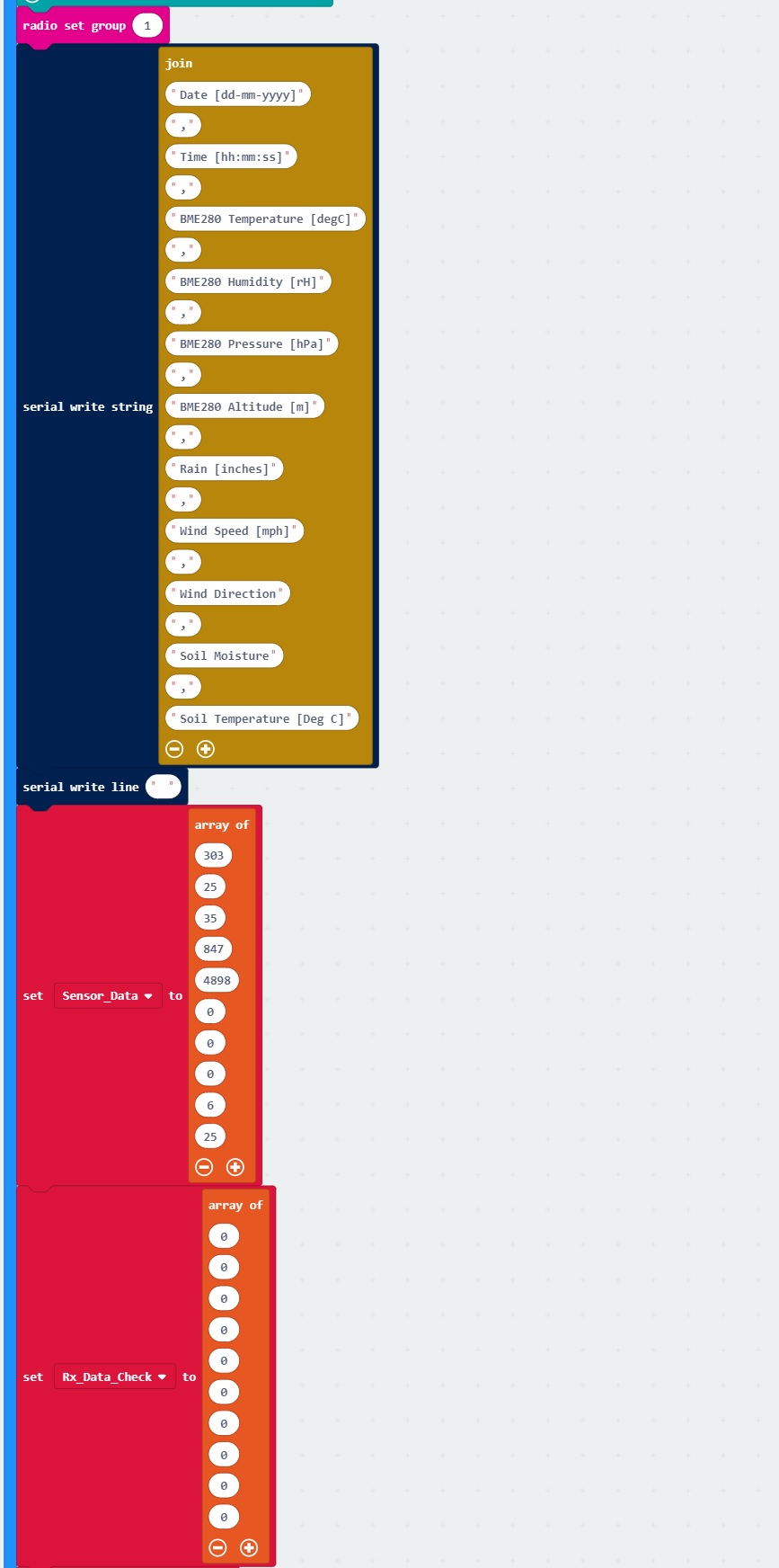
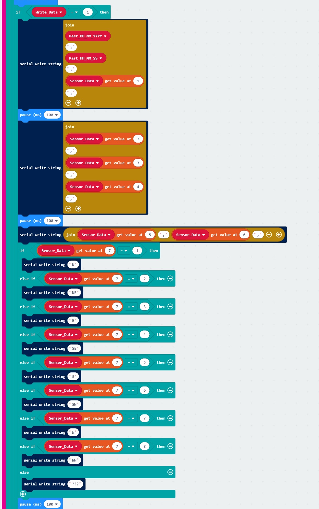
As the receiving micro:bit is powered up, we set up the serial and radio. We then create two arrays. Similar to creating regular variables, we first need to create two array variables called Sensor_Data and Rx_Data_Check from the variables block. We set each to an array of ____ ____ from the array blocks so that they are able to to save more than one number. The values in Sensor_Data are used to initialize the array for two data points from the weather station and will be used as a place holder for the array. The values in Rx_Data_Check are used to initialize the array as well but this will be used to keep track of each data point that is received for each interval. We know that the weather station will be sending two data points associated with the time and tmpC strings. We will change those values to a 1 to indicate that we have received one data point. We will assume that those two are received before the transmitting micro:bit loops back and sends the next running time and temperature. Otherwise, it will remain 0 if we did not receive anything. We also create one more variable called Total_Rx_Data and set it to 0. We only need one, which will be used to add up all the 1's from the received data points in Rx_Data_Check.

We will use the on radio received name value to listen for the string and number pair. We will use the if statement to check if we have received one of the strings sent from the first micro:bit. The first string we will check is time. If we received that as the string, we will use the array's ____ insert at ____ value ____ . The first space is for the array called Sensor_Data. The number where the second space is in the code block indicates the location that the data will be placed at. Since we expect this to be the running time, it will be at position 0 in the array. In terms of programming, this is refered to as index 0. Once inserted, everything will be shifted to the next higher position. The final space in the code block indicates the number that we will be inserted at that position; in this case the number received will be equal to the radio's variable called value. This code block is an advanced operation but it is quite useful when collecting and organizing data.
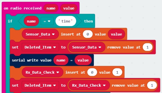
Now that we have inserted one data point into the Sensor_Data array, we will want to delete the old data point. In this case, it is the old running time. This was shifted to the next higher position, which is at position 1 in the Sensor_Data. This is important because we do not want to flood the memory and break the micro:bit. You'll probably notice a sad face with an error code when this happens. Don't worry, you can still upload new code to the micro:bit.
Just make sure to fix your code to prevent the micro:bit from being sad and not able to run any code. We will first create a variable to "throw away" the old value called Deleted_Item. We set the variable to the Sensor_Data at position 1. This is different than how we usually save numbers with variables because we will specify the position that we are removing. Since we know the old position is the next higher position, we will set that to 1. Once this block is executed, the old value is saved in Deleted_Item and we remove whatever was at Sensor_Data's position 1.
Whew, that was a lot but we are not done! Next we will send the string and number to the serial terminal to monitor what is going on. Since we received a data point for the running time, we will update the Rx_Data_Check array like we did for the Sensor_Data at position 0 by marking it as 1. We will repeat the step to remove the old information from the Rx_Data_Check.
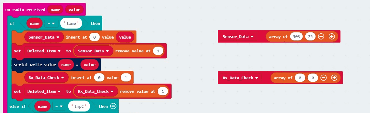
Below is a graphical representation of arrays in MakeCode of what is happening. The left is the code that is running. On the right is a graphic of what is happening to the array in the background. You will not actually see this in the MakeCode editor.
We will then exit the if statement block and head to the bottom where we blink the middle LED in the array.
The receiving micro:bit will listen for the next data point. When we receive it, the code will start executing from the top of the on radio receive name value. Since we know that the next data point to be received is tmpC, the else if statement block will jump to the next check. It will repeat all the steps as outlined earlier but for the temperature at position 1.
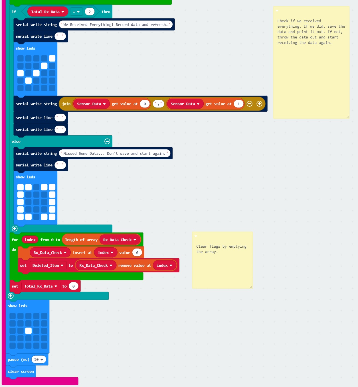
Since we know this is the last value to be received in this experiment, we will start checking to see if we received two data points inside the for loop block by adding all the 1's in Rx_Data_Check array. Each time we loop through, we will output where we are at in the Rx_Data_Check array and the current total for received data (called Total_Rx_Data). Note that programmers start counting a 0 instead of 1. The length of Rx_Data_Check array is 2. So the for loop will execute 3 times if we do subtract the length of the Rx_Data_Check array by 1.
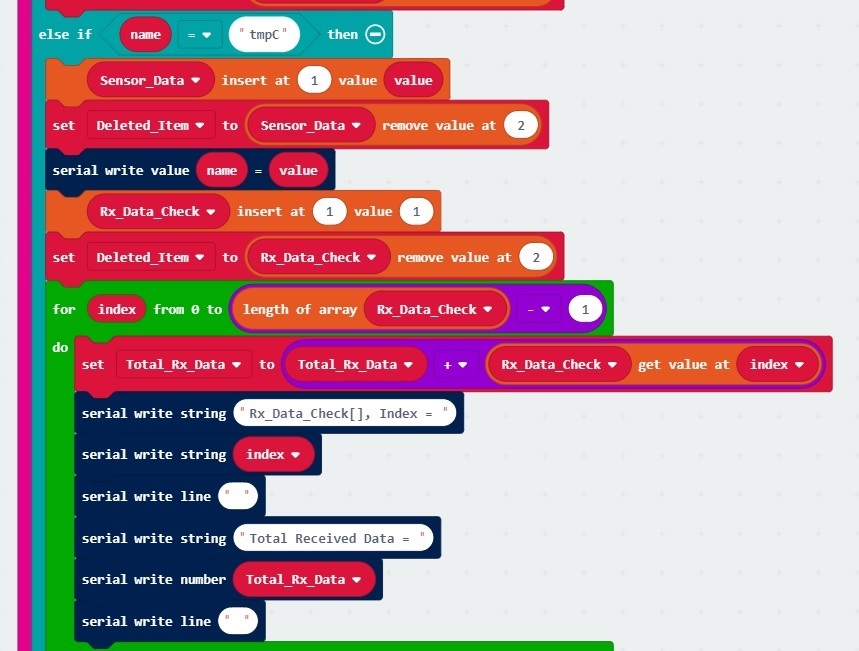
If it equals a total of 2 data points, we will output a message in the serial terminal. We will also display a check mark in the LED array, and output the readings at that instance in a comma delimited form. If it does not equal what we expect, we will output a message indicating that we did not receive everything, display a bracket [] to represent there was something missing in the array, and not output any readings for that instance. We will reset the Rx_Data_Check array and blink the LED before exiting.
We'll use the MakeCode console once again to display the serial output from the receiving micro:bit. If you have paired the micro:bit to your computer and used the one-click download feature for MakeCode, a "Show console Device" button should appear in MakeCode. Click on the button to begin viewing the serial output.
Apply power to the first micro:bit that is attached to the weather station. It will begin transmitting sensor data to the second micro:bit and display in the MakeCode console. You should see the output messages with the checks and readings for each instance. Whew, that was a lot of work to check for two data points. Let's move onto the next experiment and repeat this for the other sensor values that were sent in experiment 2
Now that we have a way to verify that the data is received, we will repeat this check for each string/number pair.
You will need the following parts:
For a few items listed, you will need more than one unit (i.e. micro:bits, micro-B USB cables, etc.). You may not need everything though depending on what you have. Add it to your cart, read through the guide, and adjust the cart as necessary.
In this section, we will be sending the same data that was transmitted in 2.1
We recommend having just the weather station's micro:bit connected for this section to avoid confusion when uploading code.
Nothing special here. The setup is the same as experiment 2. We can leave everything connected as it currently is from the previous examples.
We are going to use Microsoft MakeCode to program the micro:bit. You can download the following example script and move the *.hex file to your micro:bit. Or use it as an example to build it from scratch in MakeCode.
This is the same code that was used in 2.1! Nothing has changed on the weather station side.

In this section, we will be receiving the data and checking to see if we received everything in that instance. If we did, we will output the row in comma delimited form.
To avoid confusion when uploading code, unplug the first micro:bit from your computer. Then connect the second micro:bit to your computer via USB cable.
We are going to use Microsoft MakeCode to program the micro:bit. You can download the following example script and move the *.hex file to your micro:bit. Or use it as an example to build it from scratch in MakeCode.
The code is long but we are basically repeating what we did in experiment 3 for each reading. Let's take a look at a few of the changes.
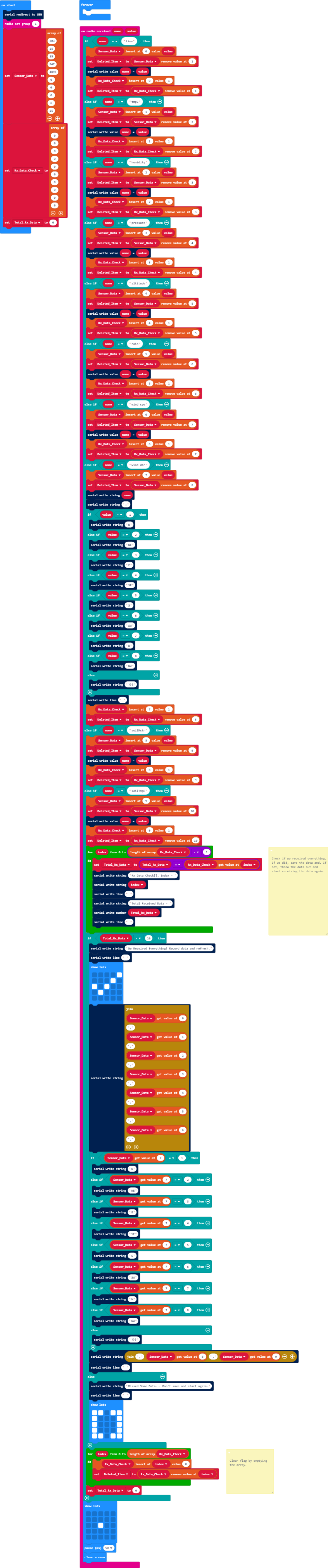
When the second micro:bit is powered up, we have the same setup as experiment 3.2. However, we will be storing and verifying 10 readings. We'll set up 10 positions for the Sensor_Data. We'll also set 10 positions to 0 for the Rx_Data_Check.
We then set condition statements to check all 10 readings. Every time we receive data, we will blink the center of the LED array. The for loop to print the received data is the same. If we received all 10 readings, we will output the data to the serial terminal. If we do not receive all 10 readings, we will not output any data like the previous experiment.

Again, we'll use the MakeCode console to display the serial output from the receiving micro:bit. If you have paired the micro:bit to your computer and used the one-click download feature for MakeCode, a "Show console Device" button should appear in MakeCode. Click on the button to begin viewing the serial output.
Apply power to the first micro:bit that is attached to the weather station. It will begin transmitting sensor data to the second micro:bit and display in the MakeCode console. You should see the output messages with the checks and an instance of the readings.
If you powered the receiving micro:bit in the middle of the transmission, it will not output the comma delimited data. Instead it will wait for the next transmission so that we have a complete row.

At the time of release, we did not have a real time clock (RTC) available for the micro:climate kit. We used the running time to record when a reading was obtained. In this experiment, we will be adding the gator:RTC to help record the day and time for each reading before saving it with the OpenLog.
You will need the following parts:
For a few items listed, you will need more than one unit (i.e. micro:bits, micro-B USB cables, etc.). You may not need everything though depending on what you have. Add it to your cart, read through the guide, and adjust the cart as necessary.
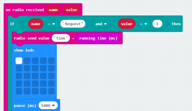
We could add the RTC to the weather station and just have the first micro:bit (let's call this micro:bit A) send the day and time. However, let's make it interesting and have the second micro:bit (we will call this micro:bit B) request this data. In this part of the experiment, we will be listening for a string/number pair before sending out the data.
We recommend having just the weather station's micro:bit connected for this section to avoid confusion when uploading code.
Nothing is new here - the setup is the same as the previous experiment. We recommend having just the weather station's micro:bit connected for this section to avoid confusion when uploading code.
We are going to use Microsoft MakeCode to program the micro:bit. You can download the following example script and move the *.hex file to your micro:bit. Or use it as an example to build it from scratch in MakeCode.
This is pretty much the same code that was used in 2.1 and 4.1 except for one addition.
The only difference is that we are now requesting the weather station's data after each interval. If we receive the request from the micro:bit B in the form of a string/value pair, we will begin sending the readings as we do in the previous examples.
In this section, we will request data from the weather station after a certain period of time has passed. If we receive everything, we will output the readings to either the serial terminal or OpenLog.
To avoid confusion when uploading code, unplug the first micro:bit from your computer. Then connect the second micro:bit to your computer via USB cable.
If you have not already, insert the microSD card into the OpenLog.
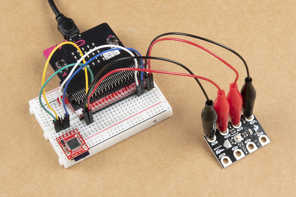
Then make the following connection using the circuit diagram. You'll need to connect a few parts together using a combination of M/M jumper wires on a breadboard. Then using the alligator with pigtails, you will need to connect the gator:RTC to the rest of the circuit.
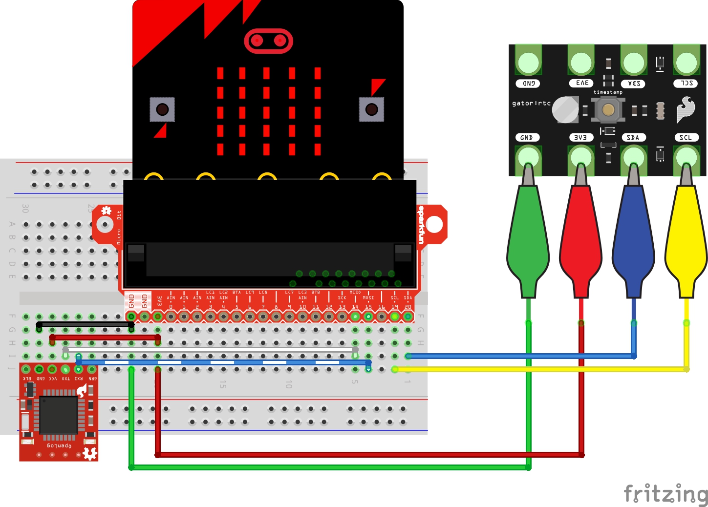
Your setup should look similar to the image below.
We are going to use Microsoft MakeCode to program the micro:bit. You can download the following example script and move the *.hex file to your micro:bit. Or use it as an example to build it from scratch in MakeCode.
This is quite a lot of code but don't worry, we did most of the work in previous examples! We are also repeating most of the steps for each sensor reading so don't feel overwhelmed. Let's inspect the changes.

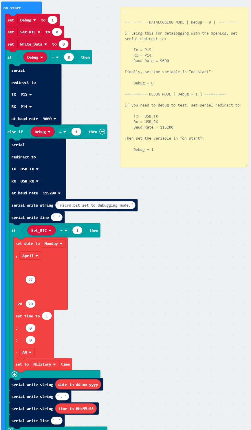
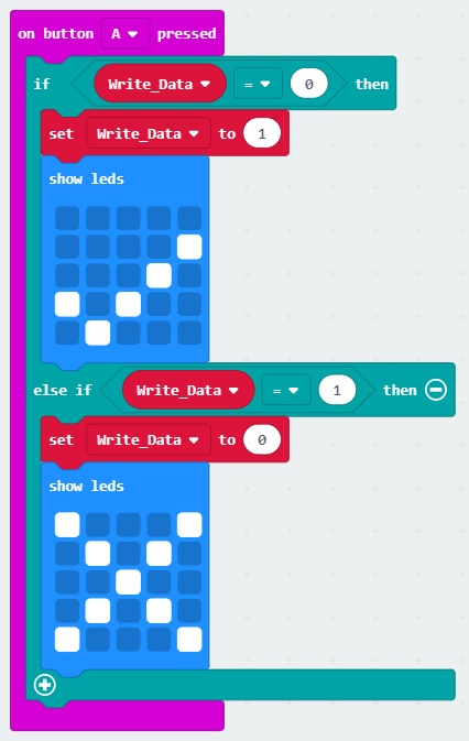
In the on start block, we want to be able to easily send serial to either the serial terminal or OpenLog. We create a variable called Debug and set it equal to 0. We also set up a variable to be able to set the RTC's day and time. We will call this Set_RTC and set it equal to 0. Write_Data is also created to output the comma delimited data and is initially set to 0.
Write_Data to 1 before uploading.
Depending on the value of Debug, we direct which of the pins to send the serial data to and adjust the baud rate as necessary using condition statements. We will also have have a condition statement for setting the day and time. If the Set_RTC is set to 1, we will set the day and time from the gator:RTC extension blocks. For simplicity and avoiding confusion, we will just use military time.
We set the radio, header to help read the data, arrays, and a variable to keep track of the total number of readings received.
The variables for Past_DD_MM_YYYY and Past_HH_MM_SS will be useful when requesting data over a certain period of time. This period of time will be our Interval in seconds and we set it equal to 30 seconds. The time it takes for all 10 string/number pairs is about ~15 seconds so we will want to give it some breathing room for micro:bit B to finish what it is doing before requesting the next set of readings. We then set up condition statements to convert the interval to either the Past_Hour, Past_Minute, or Past_Second.
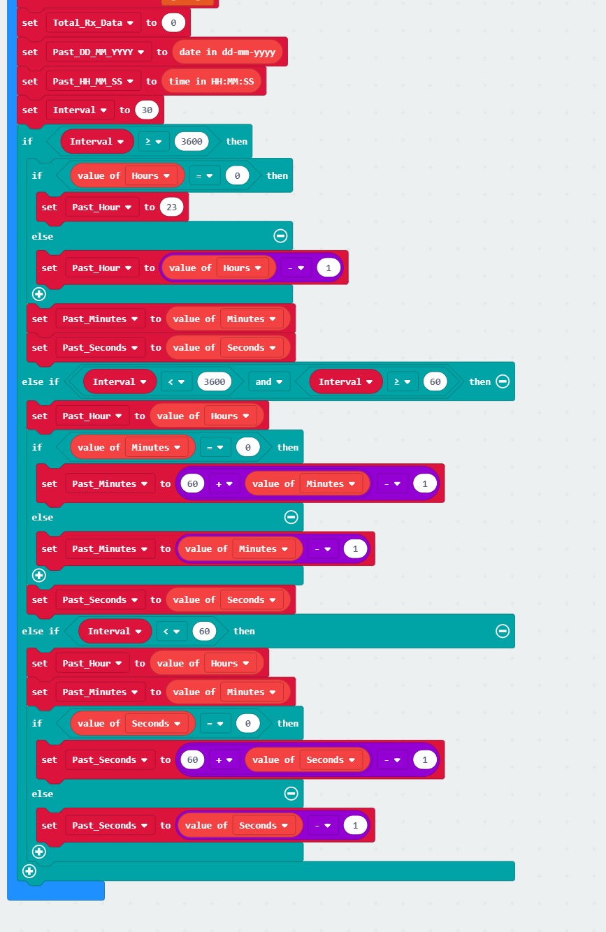
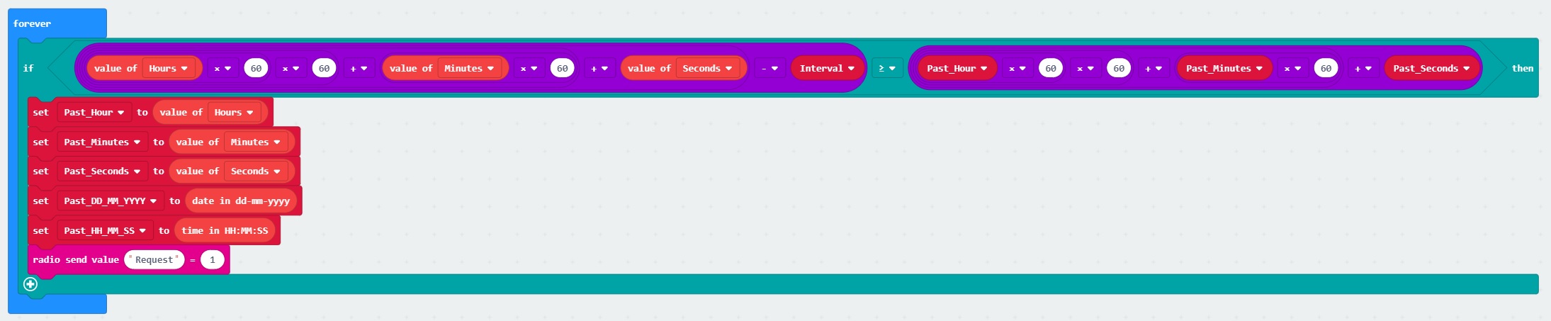
In the forever block, we will keep checking the time. Each time we jump into the if statement, we will convert the time into seconds. If the time is greater than or equal than the last time that we recorded data, we will save the date and time. We will then send a request to micro:bit A to begin sending data back.
We will not send comma delimited readings through the serial terminal or OpenLog until we press button A. If we press this button, we will begin writing serial data to either port just like we did in the micro:climate kit experiment guide.
You will notice in parts of the on radio received name value block that it is not exactly the same as the previous experiment. Since we are recording data, we do not want to also record any output that was used to debug the code. Therefore, we add an if statement to only send these messages to the serial terminal when we are in debug mode.

We will also add a small 100ms pause to give the micro:bit some time to write data to either serial port.
The code is set currently to output sensor data to the OpenLog. If you have not set up your RTC, you will need to adjust a few settings. Just before uploading the code to micro:bit B, make sure to adjust these settings:
Debug to 1Set_RTC to 1set date to _________ , _____ __ ____ to the current dateset time to __ : __ : __ AM to the current timeWhen set, pair micro:bit B to your computer to use the one-click download feature for MakeCode. Upload code and click on the "Show console Device" button begin viewing the serial output in the MakeCode console. Then power up micro:bit A that is attached to the weather station. micro:bit B will begin requesting data from micro:bit A as soon as we are within our specified interval. Press button A on micro:bit B to write data to the serial terminal.
If we received all 10 readings, we will output the date, time, and 9 readings that were received. Try changing the sensor readings on the weather station every 30 seconds to see if the values are responding to your input. If it is, we are good to start logging data!
Unplug the weather station from your computer if you are using it to power micro:bit A. Then adjust the settings to direct serial data to the Openlog and turn off any comment that was used for debugging.
Set_RTC to 0Debug to 0We will assume that micro:bit B is still paired to your computer. Click the Download button to upload code. Power up the weather station again and hit button A to start sending serial data to the OpenLog. Try changing the sensor readings on the weather station every 30 seconds and waiting a bit to obtain some sensor readings. Hit button A again to stop recording. Remove power from micro:bit B.
Insert the microSD card into a microSD card reader. Open up the saved file in your favorite text editor or spreadsheet to inspect the values. If the readings make sense, our weather station is ready! Depending on your application, try adjusting the interval to record data to 5 minutes, 15 minutes, 30 minutes, or an hour!
If you are a user of Google Sheets, try importing this data on a spreadsheet like we did at the end of the micro:climiate kit experiment guide. You can import this text file as a CSV and then graph these values pretty easily. We recommend this quick guide from Google on how to import a .txt file as a CSV into sheets.
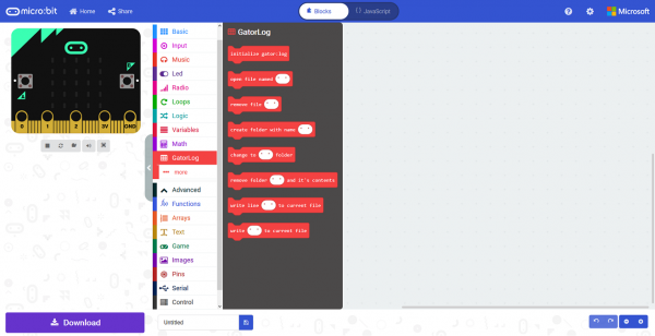
The examples created a file every time the OpenLog is powered up and we simply wrote data to one file. Can you try to write data to a specific file using the gator:log extension? Note that the OpenLog has the same functionality as the gator:log but they have a different board layout.
How hot was it today? What time was it when the day was at its coldest? Try making additional variables to keep track of the average, high, low, and/or totals for each day. Then try to cycle through the readings in a serial terminal or serial enabled LCD when pressing a button.
Try adding another sensor to the weather station's Qwiic connector. Want to monitor the UV light coming from the sun? Try adding the gator:UV to monitor UV exposure in a certain location. Or try adding a microphone to monitor noise levels in your neighborhood.
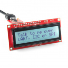
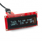
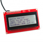
Try soldering some headers on the serial enabled LCD display and send serial data from the receiving micro:bit via serial UART or I2C port. This can display a lot more readings in a small amount of time compared to the LED array without the need for a computer. Can you toggle between each reading using buttons?
Have more than two micro:bits? Try modifying code to broadcast a signal from one micro:bit to several micro:bits by having the receiving micro:bits on the same channel!
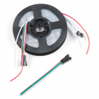
If you have the gator:bit or some WS2812-based LEDs, try having the LEDs react based on the temperature that the weather station is sensing. Or try alerting yourself with a color when the soil moisture and temperature are not ideal for your plants.
Try adding the weather station on a robot to survey the weather at different locations. You'll need a robot that is able to handle the terrain but for flat surfaces, the micro:bot will work. Try using one micro:bit for the weather station, one for the micro:bot, and one for the remote controller. Can you switch between modes to survey the environment and control the micro:bot?
Not working as expected? Below are a few troubleshooting tips to get your micro:bits working as expected. For your convenience, relevant troubleshooting tips from the micro:climate experiment guide were included below.
Not Receiving a Signal?
The Second Micro:bit is Reacting Without Sending Data from the First Micro:bit.
I Upgraded My micro:bit's Firmware and I am Unable to Pair using the WebUSB Feature.
The USB Cable is Functional and My Browser is Supported. However, I am Still Having Issues Connecting My micro:bit with the WebUSB Feature.
I Uninstalled the MBED Drivers but I am Still Having Issues Connecting My micro:bit with the WebUSB Feature.
weather:bit or gator:RTC Blocks are Not Visible.
micro:bit Not Showing Up.
Data Seems Odd and Does Not Make Sense.
I am Constantly Seeing a ??? from the Wind Vane.
??? for the wind vane, this may be due to a loose connection. Make sure that the RJ11 is fully in the socket as explained above. The micro:bit also reads the voltage from the wind vane using an analog pin. The makeCode extension was written to read 8 cardinal directions for simplicity. When the magnet closes one of the reed switches inside the wind vane, the micro:bit will read a certain value. The ??? indicates that micro:bit read the wind vane at a certain moment when the magnet was within a small region somewhere between the 8 cardinal directions. This also may be due to a conflicting pin causing an invalid reading. Try writing a condition statement to ignore this invalid data point and taking another measurement. What is North?
I am Getting a Lot of Rain?
Doesn't Seem to be Logging.
Write_Data to 1 when the variable is initialized. you may also want to check your microSD card to see if it is compatible. The Log has Weird Characters.
Now that you've successfully got your micro:bits communicating, it's time to incorporate it into your own project! If you have not already, try making an enclosure or your weather station. (The tutorial uses a different programming language but it is a good illustration of how to place your sensors in an enclosure.)
Need more inspiration? Check out our other sensors and weather stations used in other languages found in our weather section.
learn.sparkfun.com | CC BY-SA 3.0 | SparkFun Electronics | Niwot, Colorado