Wireless RC Robot with Arduino and XBees
 bboyho
Hardware Hookup
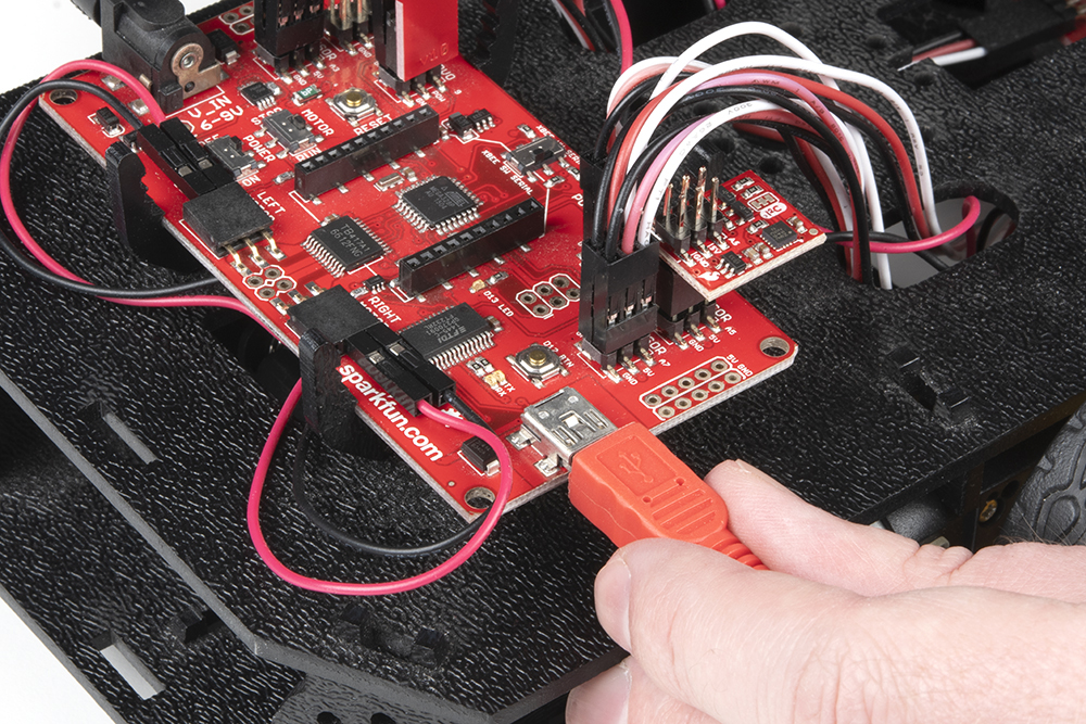
Assembled Shadow Chassis
We'll assume that you have a fully assembled robot with the Shadow Chassis.
Assembly Guide for RedBot with Shadow Chassis
Motor and Power Switches
Make sure to flip the MOTOR and POWER switches to the RUN and ON positions respectively.

Motor Wires
To be consistent with the hookup used with the assembly and experiment guide, make sure that the motor wires match the table and image below.
Left Motor:
| RedBot Mainboard Pins | Left Motor Jumper Wires |
|---|---|
| LEFT MOTOR - RED | Soldered on Motor Jumper Wire - RED |
| LEFT MOTOR - BLACK | Soldered on Motor Jumper Wire - BLACK |
Right Motor:
| RedBot Mainboard Pins | Right Motor Jumper Wires |
|---|---|
| RIGHT MOTOR - RED | Soldered on Motor Jumper Wire - BLACK |
| RIGHT MOTOR - BLACK | Soldered on Motor Jumper Wire - RED |
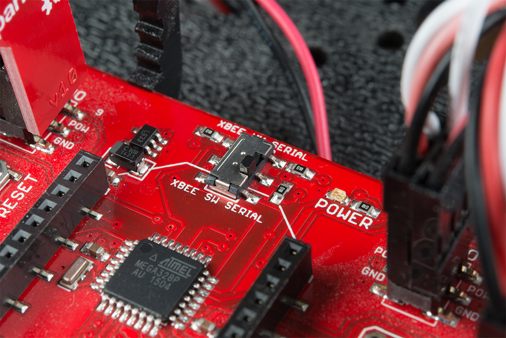
Software Serial Switch
To avoid bricking the XBee on the RedBot or uploading, it is recommended to utilize the software serial port. Make sure to flip the switch to the "XBEE SW SERIAL" side.
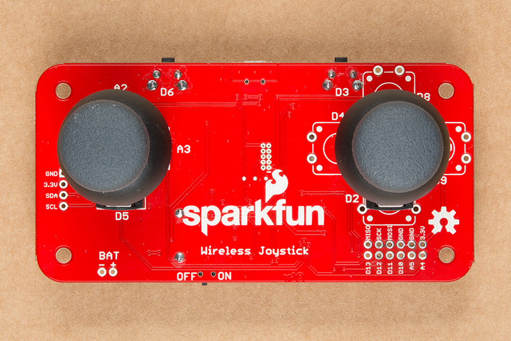
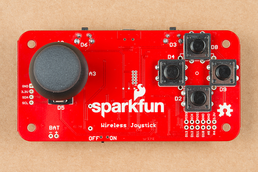
Assembled Wireless Joystick
We'll also assume that you have a wireless joystick assembled together. Check out the Hardware Hookup section in the Wireless Joystick Hookup Guide for more information. Note that you will need to solder the components together as opposed to the solderless RedBot Kit.
Wireless Joystick Hookup Guide
The example code used in this tutorial works for both the dual joystick and single joystick.
 |
 |
| Dual Joystick | Single Joystick |
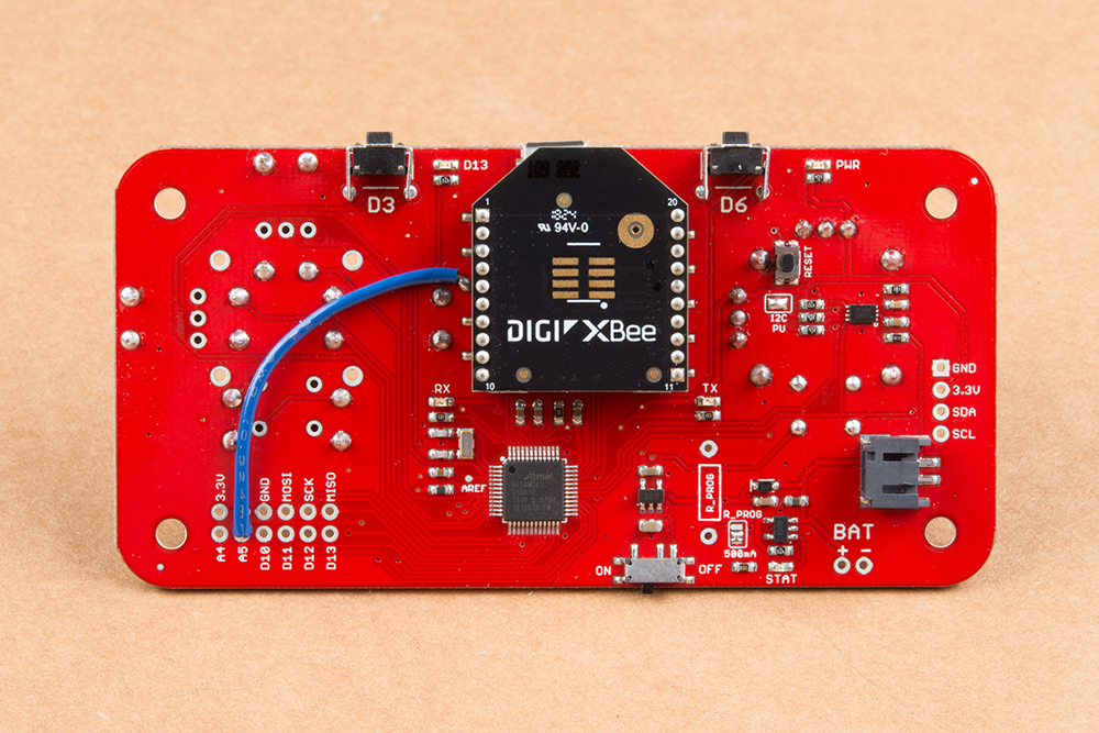
Jumper Wire for XBee 3's
The following code works with a XBee Series 1 set to transparent mode. If you are using an XBee Series 3, you may need to add a jumper between the XBee Series 3's reset pin and A5 for the Wireless Joystick. Simply cut and strip a piece of wire to add between reset pin on the XBee's female socket and A5.
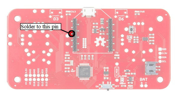
Once the wire is soldered, it should look similar to the image below.