Wireless RC Robot with Arduino and XBees
 bboyho
Experiment 1: Sending and Receiving a Signal
Introduction
There are a few methods of transmitting data between two Arduinos and a pair of XBees. You can send a serial character in transparent mode, packet in API mode, or control with an I/O pin. For simplicity, we will sending a character in transparent mode.
Parts Needed
You will need the following parts from the required materials:
- 2x XBees (Configured to Series 1 Firmware)
- 1x Cerberus Cable (or 1x micro-B USB and 1x mini-B USB Cable)
- 1x Assembled Shadow Chassis w/ RedBot Mainboard
- 4x AA Batteries
- 1x Assembled Wireless Joystick
- 1x LiPo Battery
1.1: Sending
For this part of the experiment, we are going to send a character from the controller to the RedBot on the same channel.
Hardware Hookup
If you have not already, insert the XBee and battery into the controller. Then connect the controller to your computer via USB cable.

Open the Sketch
Copy and paste the following code into the Arduino IDE. Select the SAMD21 DEV Breakout as the board, select the COM port that it enumerated on, flip the Wireless Joystick's switch to the ON position, and hit upload.
language:c
    /* 1_1_XBee_Transmit_Basic_SAMD21.ino

   XBee Transmit Basic SAMD21 Example
   Written by: Ho Yun Bobby Chan
   Date: 2/15/19
   SparkFun Electronics

   license: Creative Commons Attribution-ShareAlike 4.0 (CC BY-SA 4.0)
   Do whatever you'd like with this code, use it for any purpose.
   Please attribute and keep this license.

   This is example code for the Wireless Joystick with SAMD21. Any character entered through the
   Serial Monitor will be sent to the hardware UART pins. Assuming that you have a pair of
   XBees Series 1 modules (or Series 3 modules configured with 802.15.4 protocol) on the
   same channel, a character will be transmitted wirelessly between the XBees. The receiving
   XBee will then pass the character to the an ATmega328P microcontroller to eventually control a robot.

  Note: You may need to connect A5 to the XBee Series 3's reset pin on the Wireless Joystick
  for certain XBee Series 3 modules. For more details, check out the xbee3_RESET() function.
*/

char c_data;//send values through the serial monitor for debugging

//LED to check if the LED is initialized.
const int status_LED = 13;

//needed for certain XBee Series 3 modules
#define xbee_reset A5

void setup() {

  SerialUSB.begin(9600);// Initialize Serial Monitor for DEBUGGING

  //Uncomment this if you want to wait until the serial monitor is open.
  //while (!SerialUSB); //Wait for Serial Monitor to Open

  SerialUSB.println("Wireless Joystick Controller Initializing");
  Serial1.begin(9600); // Start serial communication with XBee at 9600 baud

  xbee3_RESET();//in case XBee3 has issues initializing, hardware reset

  //Status LED to see if the Controller is initializing
  pinMode(status_LED, OUTPUT);
  for (int i = 0; i < 3; i++) {
    digitalWrite(status_LED, HIGH);//set Status LED on
    delay(50);
    digitalWrite(status_LED, LOW); //set Status LED off
    delay(50);
  }

  SerialUSB.println("Wireless Joystick Controller's XBee Ready to Communicate");
  delay(10);
}//end setup

void loop() {

  //send commands via serial monitor for testing here
  if (SerialUSB.available()) {
    c_data = SerialUSB.read();//take character from serial monitor and store in variable

    Serial1.print(c_data);//send to XBee

    //echo back what was sent to serial monitor
    SerialUSB.println("Sending Character Here, ");
    SerialUSB.println(c_data);
    digitalWrite(status_LED, HIGH); //turn ON Status LED

  }

  delay(100);//add short delay for LED for feedback, this can be commented out if it is affecting performance
  digitalWrite(status_LED, LOW); //turn OFF Status LED
}//end loop

void xbee3_RESET() {

  //HARDWARE RESET
  /*
    - XBee Series 3 Hardware Reference Manual
    - Pg 31 Power Supply Design recommends decoupling capacitor between Vcc and GND.
      Tested with 10uF capacitor and without. This was not necessary.
    - Pg 60 Brown Out Detection. This is REQUIRED. Add a jumper between the XBee's Reset and A5
    https://www.digi.com/resources/documentation/digidocs/pdfs/90001543.pdf

    - Power cycle XBee Series 3 by grounding RESET Pin to avoid dicontinuities in ramp up and brown out detection
    https://www.silabs.com/community/mcu/32-bit/knowledge-base.entry.html/2017/06/14/rmu_e203_avdd_ramp-j176

    - Minimum Time to Force Reset:
    - EFM32 devices = 50ns; EFM32PG/JG: Pearl and Jade Gecko =100ns
    https://www.silabs.com/community/mcu/32-bit/knowledge-base.entry.html/2016/07/22/minimum_reset_holdt-PglD
  */
  pinMode(xbee_reset, OUTPUT);
  digitalWrite(xbee_reset, HIGH);
  delayMicroseconds(1);
  digitalWrite(xbee_reset, LOW);
  delayMicroseconds(1);
  digitalWrite(xbee_reset, HIGH);

  /*
    //SOFTWARE RESET
    //Software reset does not work with XBee Series 3... Needs a hardware reset
    delay(500);//wait until XBee Series 3 to start up after hardware reset
    Serial1.write("+++"); //Enter Command Mode
    delay(500);//short delay as the XBee gets into command mode
    Serial1.write("ATFR");//AT command for software reset
    Serial1.write("\r");//carriage return
    Serial1.write("\n");//new line
  */
}
Code to Note
The code sets up a variable to keep track of the character being sent, an LED for indicator on pin 13 when we are sending a character, and a pin to reset the XBee. Since the controller uses the SAMD21, we will initialize the serial monitor for debugging usingSerialUSB and the hardware serial using Serial1 to send characters using an XBee at 9600 baud. The code will briefly toggle A5 to reset an XBee 3 when the board is powered up in our custom function called xbee3_RESET(). Once we are finished initializing, the LED will blink three times. Then we will listen to the serial monitor for any characters in an if() statement. If a character is sent through the serial terminal, we will pass the character on to the XBee and echo it back to the serial monitor for debugging.
1.2: Receiving
For this part of the experiment, we are going to have the RedBot receive a character from the first controller.
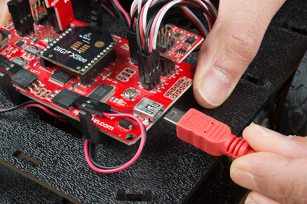
Hardware Hookup
If you have not already, insert the XBee into the RedBot. Then connect the Redbot to your computer via USB cable.
Open the Sketch
Copy and paste the following code into the Arduino IDE. Since we are uploading code for the RedBot Mainboard, we will need to select Arduino/Genuino Uno for the RedBot mainboard, select the corresponding COM port that it enumerated on, and flip the POWER switch to the ON position. Once these settings are adjusted, you can hit the upload button.
language:c
   /* 1_2_XBee_Receive_Basic_ATmega328P.ino
   XBee Receive Basic ATmega328P Example
   Written by: Ho Yun Bobby Chan
   Date: 2/15/19
   SparkFun Electronics

   license: Creative Commons Attribution-ShareAlike 4.0 (CC BY-SA 4.0)
   Do whatever you'd like with this code, use it for any purpose.
   Please attribute and keep this license.

   The first step to controlling the RedBot remotely is to first drive it
   from the Serial Monitor in a tethered setup. This is example code
   for the RedBot Mainboard with ATmega328P. After uploading this sketch,
   keep the RedBot tethered to your computer with the USB cable. Flip the
   switches to the respective sides: MOTOR => RUN and POWER => ON. You
   will also need to have UART flipped to the XBee_SW_Serial side.

   Assuming that you have a pair of XBees 1s (or 3 configured with
   802.15.4 protocol) on the same channel, a character will be
   transmitted wirelessly between the XBees. Any charactered received
   from the XBee connected to the software serial defined pins will
   be passed to the Serial Monitor. For troubleshooting, any character
   sent through the Serial Monitor will be echoed back.

*/

#include <RedBot.h>  //include RedBot library

char c_data;  // variable for holding incoming data from XBee to Arduino

// We'll use RedBot SoftwareSerial to communicate with the XBee:
// For Atmega328P's
// XBee's DOUT (TX) is connected to pin 14 (Arduino's Software RX)
// XBee's DIN (RX) is connected to pin 15 (Arduino's Software TX)
#include <RedBotSoftwareSerial.h>
RedBotSoftwareSerial RedBotXBee; //make instance of Software Serial, pins defined already in modified Software Serial Library

//LED to check if the LED is initialized.
const int status_LED = 13;

void setup() {
  // Set up both ports at 9600 baud. This value is most important
  // for the XBee. Make sure the baud rate matches the config
  // setting of your XBee.
  RedBotXBee.begin(9600);// Initialize SW for XBee for receiving serial
  Serial.begin(9600);// Initialize HW for Serial Monitor for DEBUGGING

  //Status LED to see if the RedBot is initializing
  pinMode(status_LED, OUTPUT);
  for (int i = 0; i < 3; i++) {
    digitalWrite(status_LED, HIGH);//set Status LED on
    delay(50);
    digitalWrite(status_LED, LOW); //set Status LED off
    delay(50);
  }

  Serial.println("RedBot Initialized!");
}//end setup

void loop() {

  if (RedBotXBee.available() || Serial.available()) {
    if (RedBotXBee.available()) {
      c_data = RedBotXBee.read();//store received value from XBee into variable

    }

    else if (Serial.available()) {
      c_data = Serial.read();//store received value from Serial Monitor into variable

    }

    Serial.println("Character Received, ");
    Serial.write(c_data);//send it out to serial monitor
    Serial.println();
    digitalWrite(status_LED, HIGH); //turn ON Status LED
    delayMicroseconds(500);//add short delay for LED for feedback, this can be commented out if it is affecting performance

  }

  digitalWrite(status_LED, LOW); //turn OFF Status LED
}//end loop
Code to Note
The code for the RedBot is similar to the SAMD21. However, since we are using the ATmega328, we will be setting up the software serial to receive characters from the XBee. The RedBot uses a custom software serial so we will need to include the <RedBotSoftwareSerial.h>. We will initialize the serial monitor for debugging using Serial and the software serial using using RedBotXBee to receive the characters from the XBee at 9600 baud. When using an XBee 3 with the RedBot mainboard, the XBee 3 did not have any issues during its initial power up so there was no need to toggle the XBee 3's reset pin. Once we are finished initializing, the LED will blink three times again. Then we will listen to the serial monitor or software serial for any characters received in the if() statement. If a character is received, we will display the character in the serial monitor for debugging.
What You Should See
We'll open a serial terminal for each board to see if a character was sent from the controller to the RedBot. For the controller, we'll open a serial terminal at 9600 that the controller enumerated on. For the RedBot, we'll use the Arduino serial monitor at 9600 since we just uploaded code to the board. Sending any character in the serial terminal will echo back and the have controller's XBee wirelessly transmit a character to the RedBot's XBee. Once received, the character will display in th Arduino serial monitor.
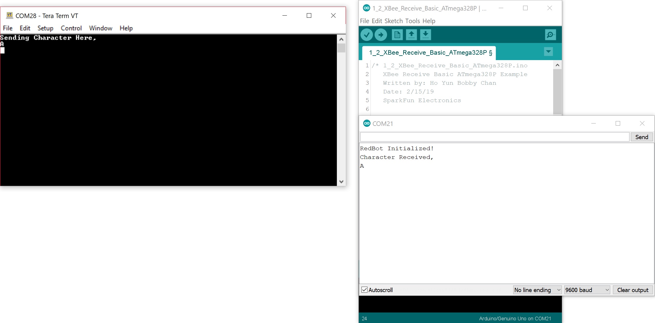
Congratulations, you have successfully sent a character wirelessly between two Arduinos!