Assembly Guide for RedBot with Shadow Chassis
 HelloTechie,
  SFUptownMaker,
  Shawn Hymel
6. Mainboard
In this section, you will add brains of the robot: the RedBot Mainbooard.
Locate the Following:
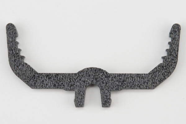
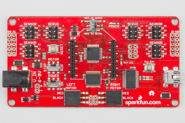
| 2x Mainboard Mount (G) | 1x RedBot Mainboard (P) | |
 |
 |
> |
You will also need the full chassis assembly, which contains any additional parts and sensors you attached in previous steps.
Attach the Mainboard Mounts
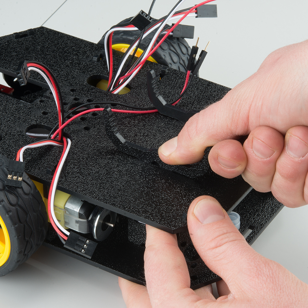
Snap the two Mainboard Mounts (G) into the vertical slots in the back of the top chassis plate near the large rectangular opening.
Add the Mainboard
The RedBot Mainboard (P) snaps into the lowest of the notches on the Mainboard Mounts (G). Make sure the power jack is facing the left side of the robot. Push gently and evenly until it snaps into place.
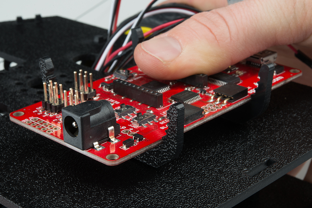
NOTE: The other slots in the mainboard mounts can be used to hold the Arduino UNO or the SparkFun RedBoard.
Connecting the Cables
It is time to connect the jumper wires; it is really important that these connections are right.
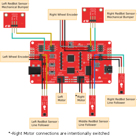
You can follow along with the pin out tables or scroll down for a diagram. Trace each cable poking through the top chassis plate to make sure you know what it is connected to.
If you have the RedBot Basic Kit, disregard any extra sensors that are missing in your kit. These sensors will be marked with the label (SIK).
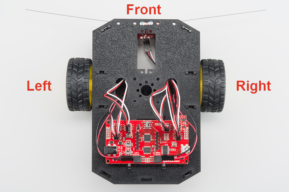
Please note: When you have the RedBot upright and the front of the chassis facing away from you, "left" sensors/motors will be on the left side and "right" sensors/motors will be on the right side. Also - the motor wires are intentionally switched for the right motor -- see notes below.
Line Followers
Left Line Follower:
| RedBot Mainboard Pins | Jumper Wires | Left Line Follower Board |
|---|---|---|
| A3 | 3-Wire Jumper Cable - White | OUT |
| 5V | 3-Wire Jumper Cable - Red | VCC |
| GND | 3-Wire Jumper Cable - Black | GND |
Center Line Follower:
| RedBot Mainboard Pins | Jumper Wires | Middle Line Follower Board |
|---|---|---|
| A6 | 3-Wire Jumper Cable - White | OUT |
| 5V | 3-Wire Jumper Cable - Red | VCC |
| GND | 3-Wire Jumper Cable - Black | GND |
Right Line Follower:
| RedBot Mainboard Pins | Jumper Wires | Right Line Follower Board |
|---|---|---|
| A7 | 3-Wire Jumper Cable - White | OUT |
| 5V | 3-Wire Jumper Cable - Red | VCC |
| GND | 3-Wire Jumper Cable - Black | GND |
Whisker Mechanical Bumpers
Left Mechanical Bumper (SIK):
| RedBot Mainboard Pins | Jumper Wires | Left Bumper Board |
|---|---|---|
| 3 | 3-Wire Jumper Cable - White | OUT |
| POW | 3-Wire Jumper Cable - Red | 5V |
| GND | 3-Wire Jumper Cable - Black | GND |
Right Mechanical Bumper (SIK):
| RedBot Mainboard Pins | Jumper Wires | Right Bumper Board |
|---|---|---|
| 11 | 3-Wire Jumper Cable - White | OUT |
| POW | 3-Wire Jumper Cable - Red | 5V |
| GND | 3-Wire Jumper Cable - Black | GND |
Motors
Left Motor:
| RedBot Mainboard Pins | Left Motor Jumper Wires |
|---|---|
| LEFT MOTOR - RED | Soldered on Motor Jumper Wire - RED |
| LEFT MOTOR - BLACK | Soldered on Motor Jumper Wire - BLACK |
Right Motor:
| RedBot Mainboard Pins | Right Motor Jumper Wires |
|---|---|
| RIGHT MOTOR - RED | Soldered on Motor Jumper Wire - BLACK |
| RIGHT MOTOR - BLACK | Soldered on Motor Jumper Wire - RED |
Motor Encoders
Left Wheel Encoder (SIK):
| RedBot Mainboard Pins | Jumper Wires | Left Wheel Encoder |
|---|---|---|
| A2 | 3-Wire Jumper Cable - White | OUT |
| POW | 3-Wire Jumper Cable - Red | 5V |
| GND | 3-Wire Jumper Cable - Black | GND |
Right Wheel Encoder (SIK):
| RedBot Mainboard Pins | Jumper Wires | Right Wheel Encoder |
|---|---|---|
| 10 | 3-Wire Jumper Cable - White | OUT |
| POW | 3-Wire Jumper Cable - Red | 5V |
| GND | 3-Wire Jumper Cable - Black | GND |
Diagram