Assembly Guide for RedBot with Shadow Chassis
 HelloTechie,
  SFUptownMaker,
  Shawn Hymel
3. Line Follower
In this section, you will be putting standoffs on the RedBot Sensor - Line Followers. Then you will add the sensors to your chassis.
Locate the Following:
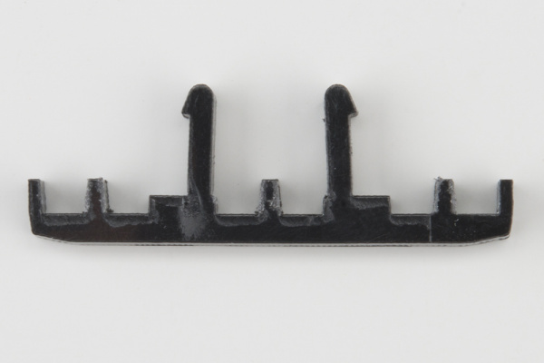
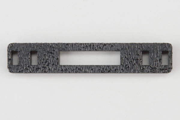
| 1x Line Follower Mount (I) | 1x Line Follower Mount Plate (J) | 3x Line Follower Board (Q) |
 |
 |
 |
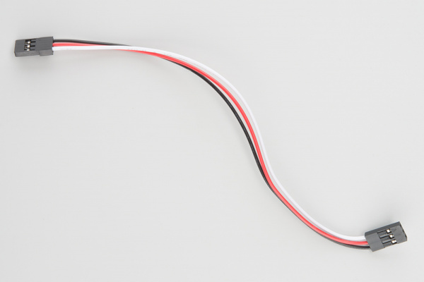
| 3x 3-Wire Jumper Cable (Y) | ||
 |
> |
Construct the Line Follower Assembly
Attach the 3 Line Follower Boards (Q) to the Line Follower Mount (I) such that the rectangular pegs in the Line Follower Mount poke through the mounting holes in the Line Follower Boards. Make sure the sensors are facing away/down from the clip of the mount.
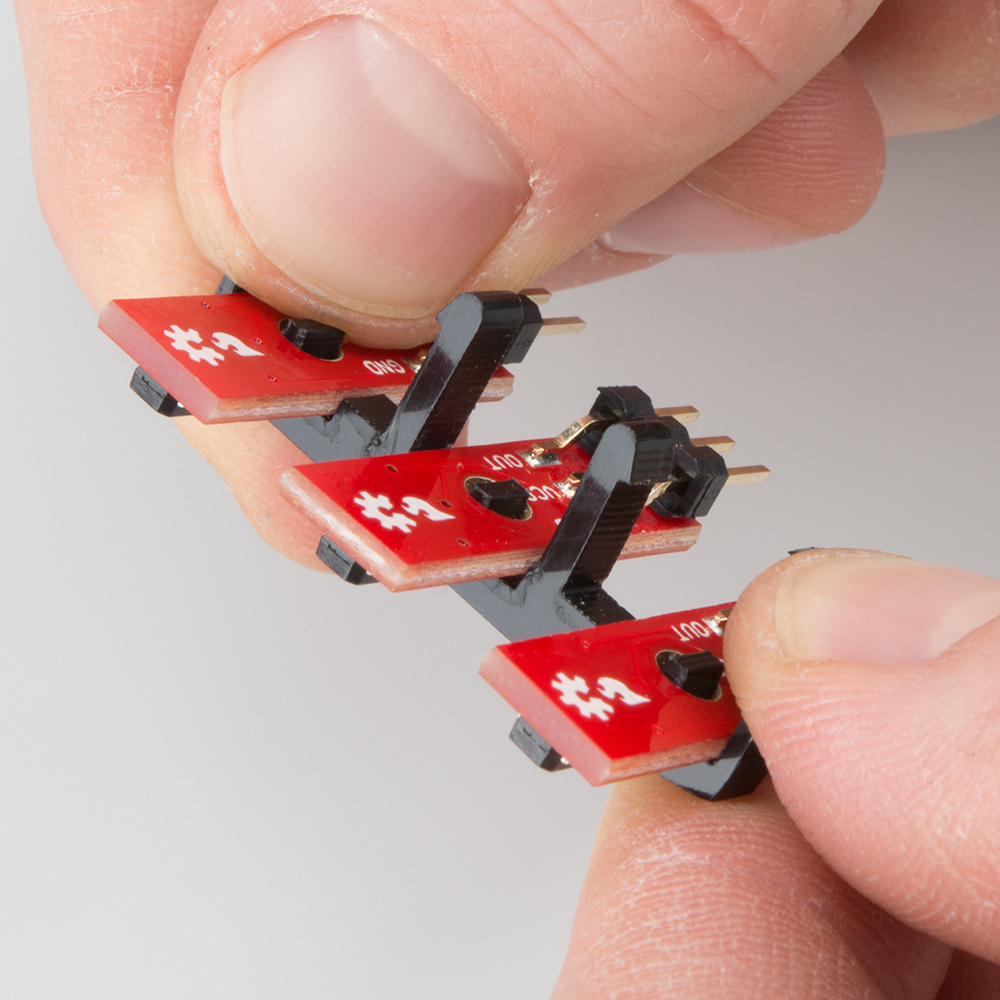
Place the Line Follower Mount Plate (J) on top of the Line Follower Mount (I) so that the center clip of the mount is poking through the center slot of the plate.

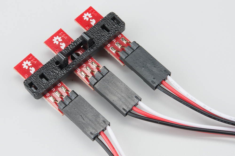
Attach the Cables
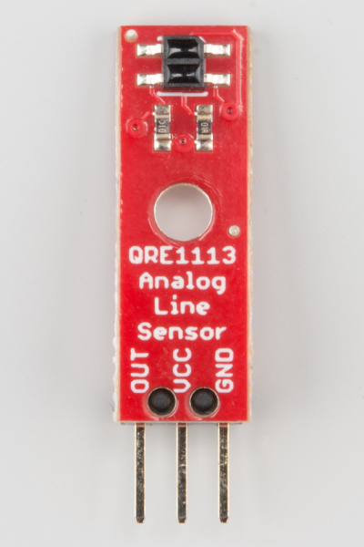
You will need to connect a 3-Wire Jumper Cable (Y) to each of the Line Follower Boards (Q). Note the color of the wire attached to each pin.
Line Follower Connections:
| Jumper Wire Color | RedBot Sensor - Line Follower |
|---|---|
| Black | GND |
| Red | VCC |
| White | OUT |
Attach all 3 cables to the 3 Line Follower Boards. Notice that the white wire should be on the right and the black wire should be on the left.
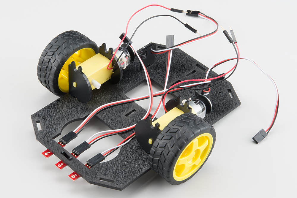
Attach the Line Follower Assembly to the Chassis
Locate the wide, rectangular slot near the front of the chassis and snap the line follower assembly in from the bottom side of the chassis. Route the cables through the large hole in the bottom plate.