Assembly Guide for RedBot with Shadow Chassis
 HelloTechie,
  SFUptownMaker,
  Shawn Hymel
4. Mechanical Bumpers (SIK)
Read on if you have the SIK for RedBot or are using the Mechanical Bumpers. If not, skip to the next section.
One of the sensors included in the SIK for RedBot are a set of Whisker Mechanical Bumpers. These are basically simple switches that close a circuit when the whisker pushes against an object. The whiskers are made from a thick music wire and a simple RedBot Bumper board. You will need to prepare the music wire by bending the wire itself. Then, you will add standoffs and screws to your mechanical bumpers, followed by adding the mechanical bumpers to the RedBot chassis.
Locate the Following:
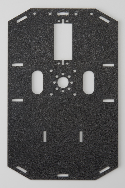
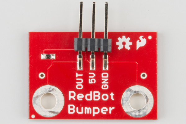
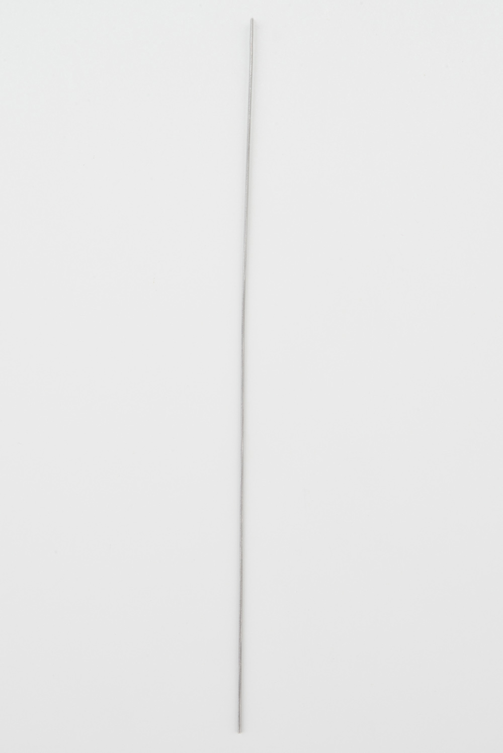
| 1x Top Chassis Plate (B) | 2x Bumper Board (T) | 2x Bumper Whisker (U) |
 |
 |
 |
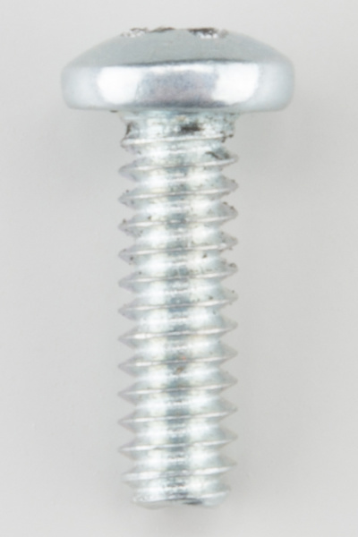
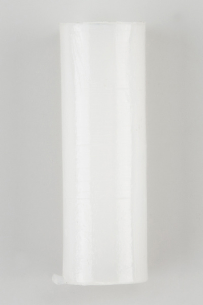
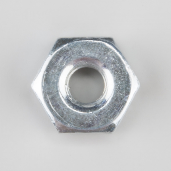
| 6x #4-40 x 3/8" Screw (V) | 2x #4-40 Nylon Standoff (W) | 2x #4-40 Hex Nut (X) |
 |
 |
 |
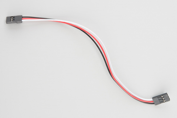
| 2x 3-Wire Jumper Cable (Y) | 1x Phillips Screwdriver (AB) | |
 |
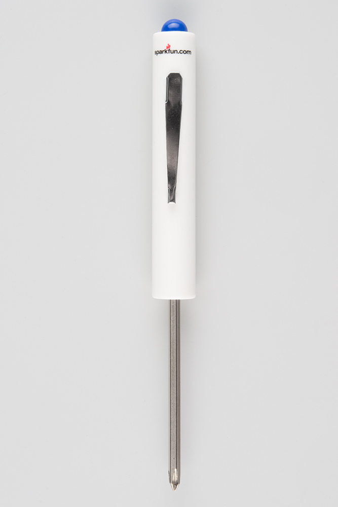 |
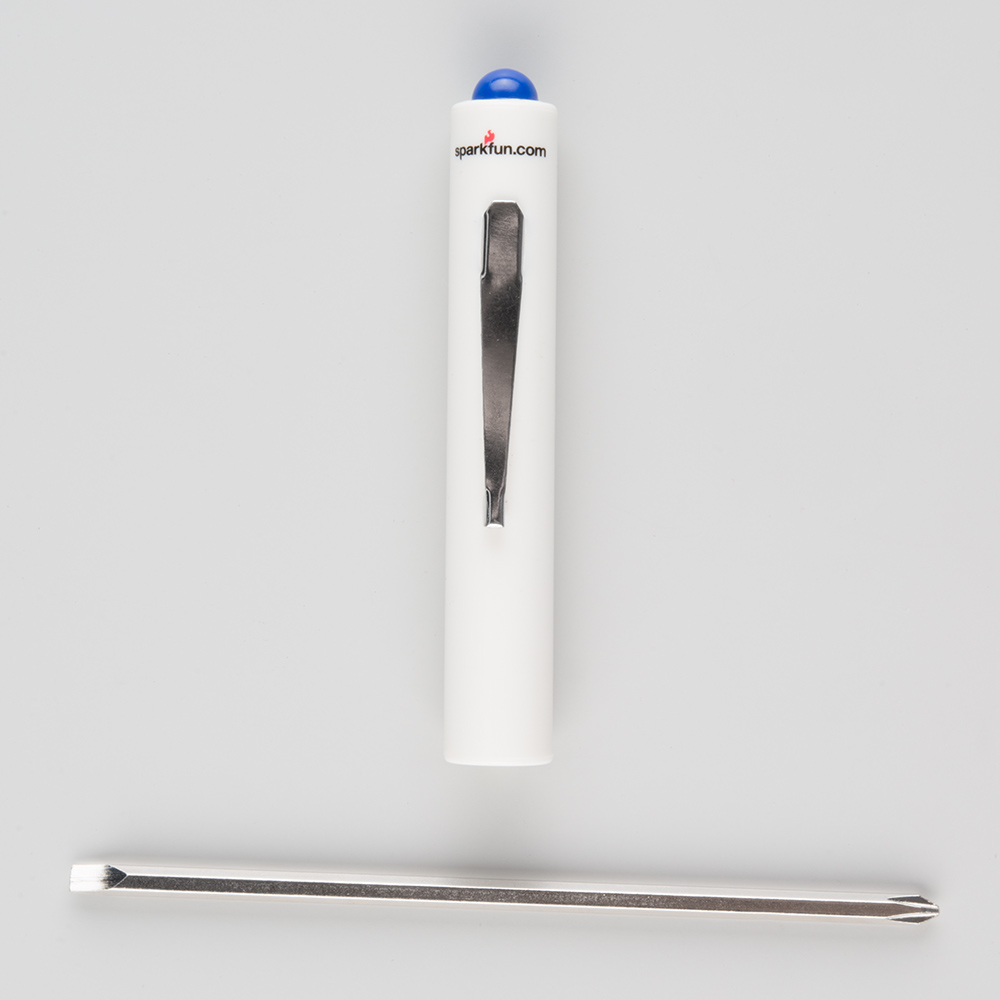
A Note About the Screwdriver
The Mini Screwdriver contains a flat-head and Phillips head. To change to the Phillips head, you might have to remove the metal shaft, turn it around, and insert it back into the plastic handle.
Prepare the Mechanical Bumpers
Screw a #4-40 x 3/8" screw (V) and #4-40 hex nut (X) to one of the two large mechanical bumper holes. You can get it pretty tight with just your fingers, but we've included a screwdriver screwdriver (AB) in your kit. Note that the screwdriver has both a Phillips and a regular head. Pull the screwdriver out of the handle to change the head.
Time to bend the whisker!
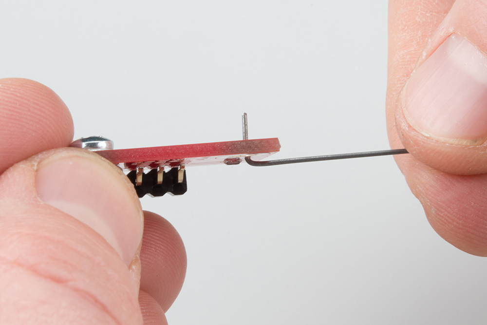
It is easy to bend the whisker using needle nose pliers. However, there is a trick to bend the whisker using the Mechanical Bumper Board itself. First, stick one of the whiskers (U) through one of the smaller side holes. It only needs to stick out a little bit.
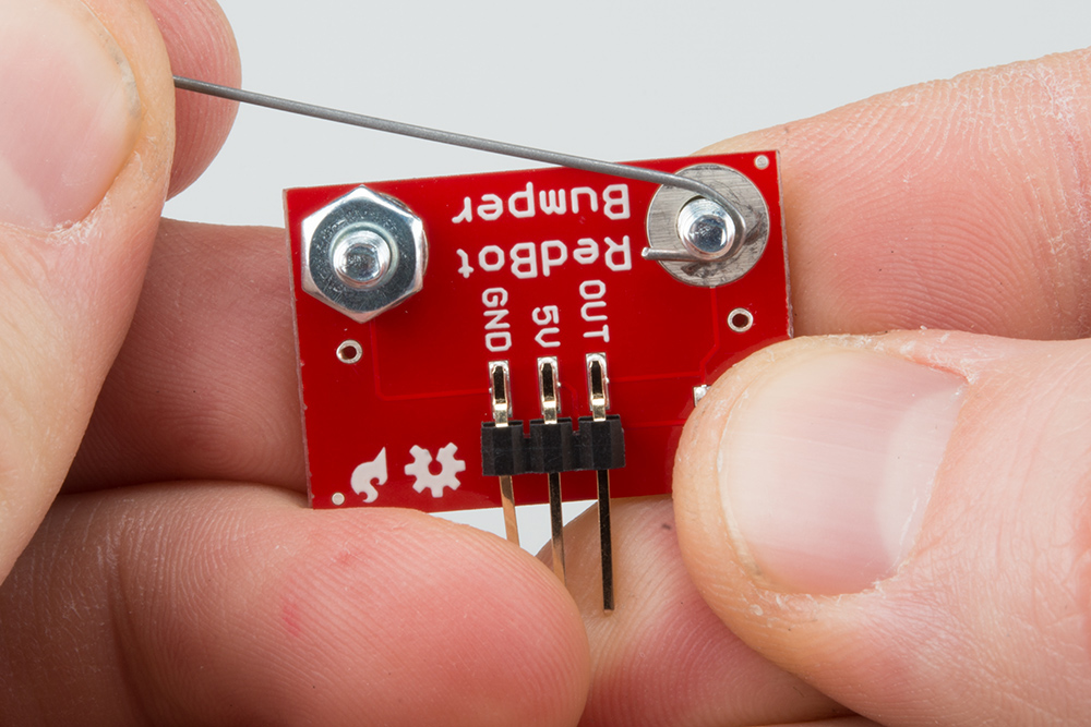
Bend the whisker 90 degrees.
Bend the whisker 90 degrees again.

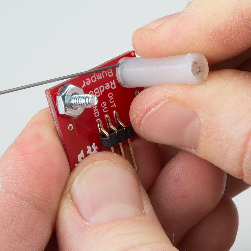
Now that the whisker is bent, take the wire out of the PCB hole. Add a #4-40 x 3/8" Screw (V) from the bottom and loop the bent whisker around the screw. Hold this tight and secure it with a the #4-40 nylon standoff.
Note: It is very important that you do not let the whisker touch the hex nut or screw on the other side. This is what triggers the sensor. Leave a little space between the wire and other side's nut.
Twist and tighten the #4-40 nylon standoff on top of the screw to secure the whisker.
Double check that the whisker does not touch the #4-40 hex nut or screw on the other side. Use the screwdriver to tighten the screw with out moving the position of the whisker.

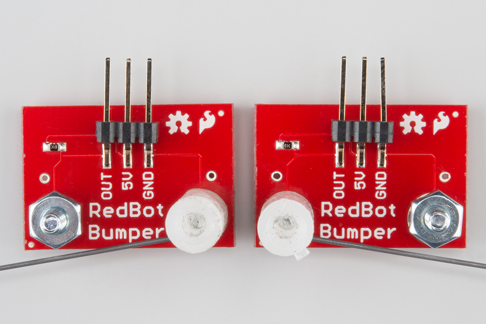
We want to opposing whiskers. Take note of which side your #4-40 x 3/4" standoff is on for the first mechanical bumper. Do the opposite for the other bumper. Double check that there is one mechanical bumper that has a #4-40 x 3/4" standoff on the right side of the "RedBot Bumper" silkscreen and one that has a #4-40 x 3/4" standoff on the left side.
Attach the Bumpers to the Chassis
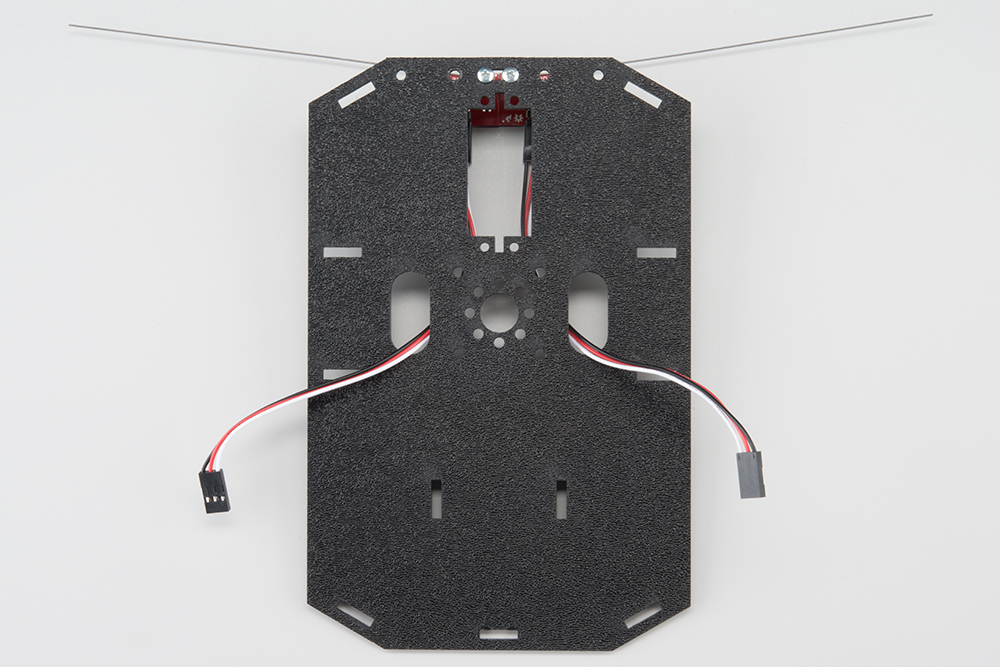
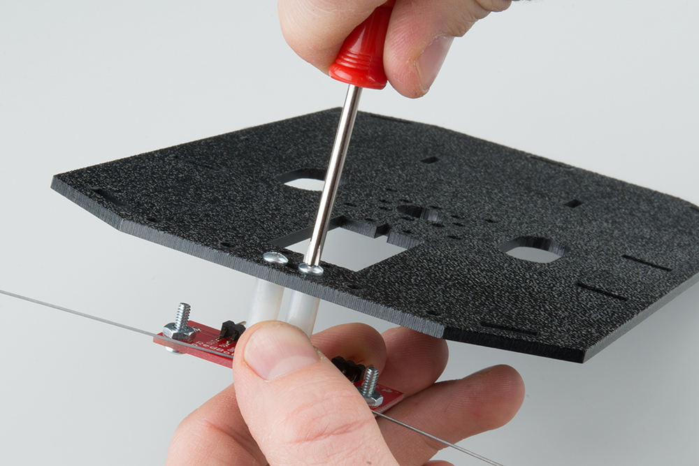
Locate the wide rectangular slot on the front of the Top Chassis Plate (B). Notice the four circular holes as well. This is the front of the chassis.
Using two #4-40 x 3/8" Screws (V), tighten down the bumper assemblies with the two wires pointing in opposite directions on the bottom side of the top chassis plate. The mechanical bumpers' header pins should be pointing toward the center of the chassis piece.
Attach the Cables
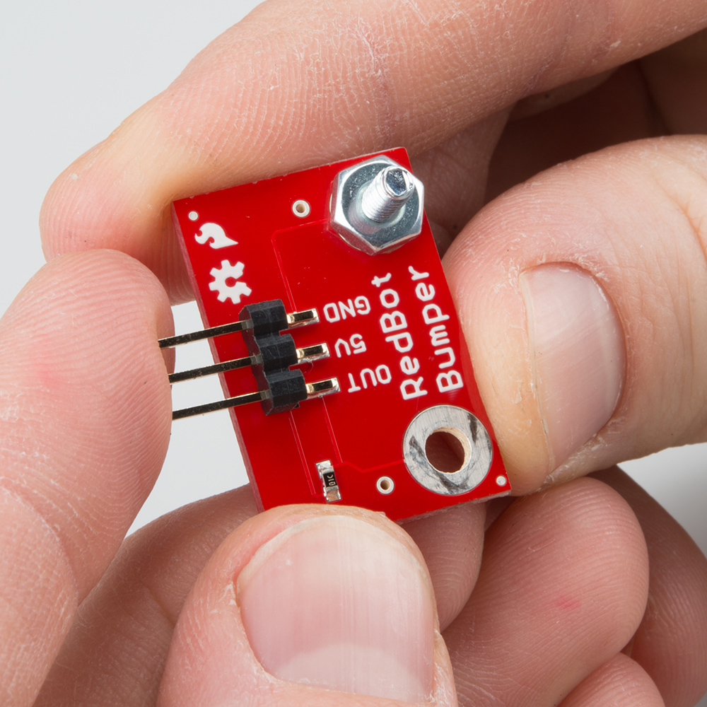
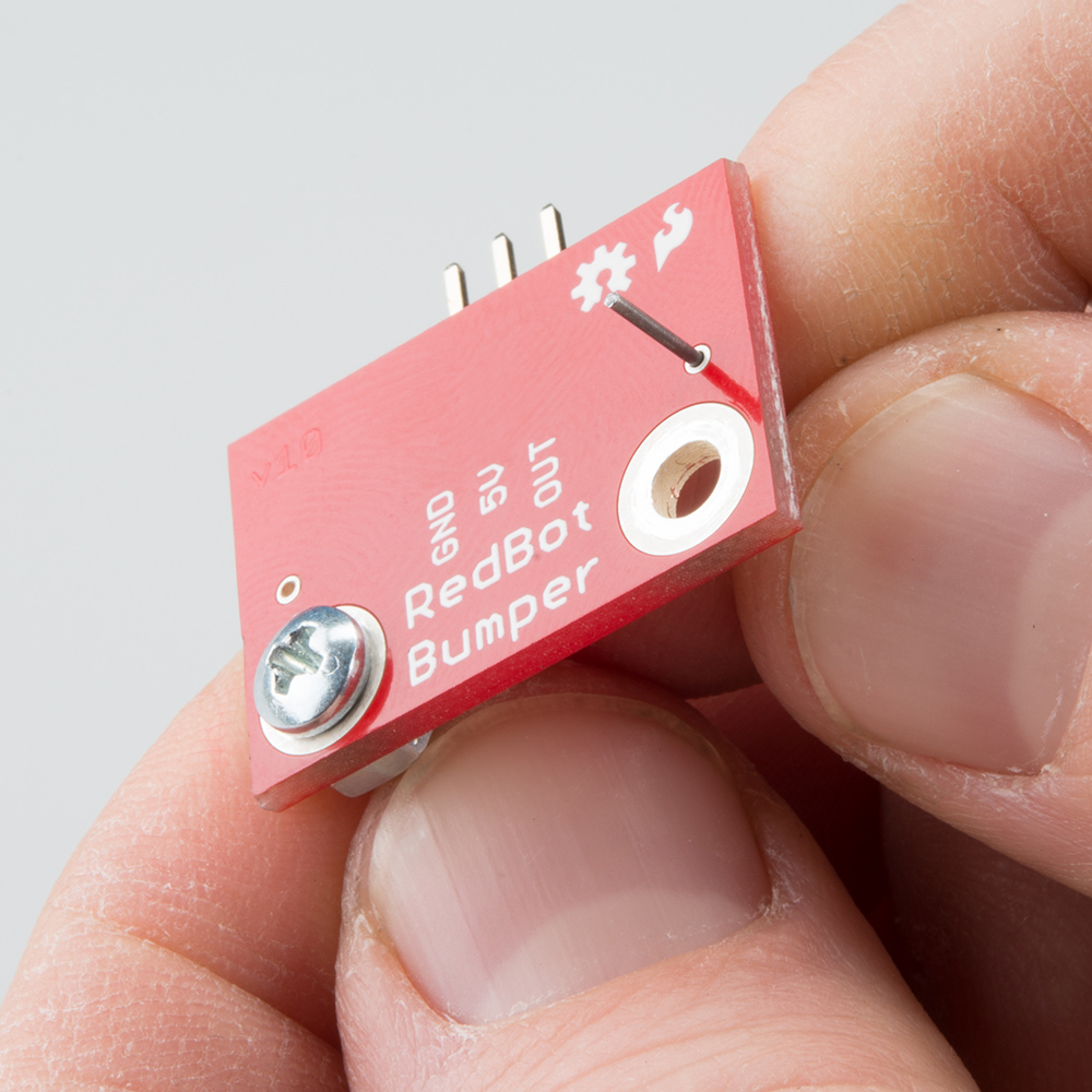
You will need to connect a 3-Wire Jumper Cable (Y) to each of the Bumper Boards (T). Note the color of the wire attached to each pin.
Bumper Connections:
| Jumper Wire Color | RedBot Sensor - Line Follower |
|---|---|
| Black | GND |
| Red | VCC |
| White | OUT |
Attach both cables to the 2 Bumper Boards.

Route the cables through the left and right oval cutouts, respectively.