WiFly Shield Hookup Guide
 Joel_E_B,
  CTaylor
Introduction
The WiFly Shield allows you to easily connect your Arduino to a wireless network, serve up data, act as a client, create an ad-hoc network for your Internet of things devices, and get data such as data and time from your network. This hookup guide will show you how get started, how to configure the WiFly module, and how to set up some simple sketches using the WiFly Shield.

Covered in This Tutorial
This guide will show you:
- How to connect the WiFly Shield to the Arduino
- How to communicate with the WiFly Shield through the terminal
- How to connect the WiFly to a WiFi network
- Simple communication over a network
- How to create a simple server
- How to update the firmware on the WiFly module
All of the functions and commands used in this tutorial can be found in the RN131 documentation:
- RN131 Product Page
- RN131 Reference Guide
- [RN131 Datasheet](link text
- SC16IS750 SPI to UART Bridge Datasheet
Suggested Reading
If you’re new to electronics or wireless communication, you may also want to check out these other concepts first:
- Installing an Arduino Library
- What is a Shield?
- Serial Communication
- SPI Communication
- Serial Terminal Basics
- How to Solder
You should also have a basic understanding of simple networking terms such as:
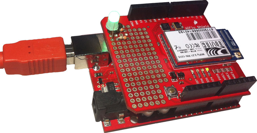
Hardware Overview

The WiFly Shield consists of two major components:
The WiFly module communicates via its UART to the SC16IS750 bridge chip, which in turn communicates with the Arduino via SPI.

This allows the WiFly module to communicate with the Arduino at high speed without using the Arduino’s UART so that the Arduino can still communicate with a serial terminal. Any communication from the WiFly to the Arduino (or vice versa) must be sent through the SC16IS50.
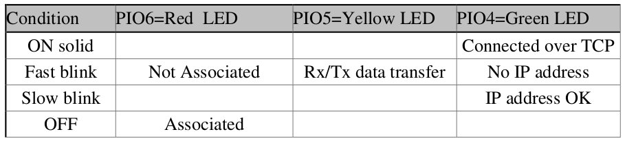
The WiFly module is connected to four indicator LEDs through its I/O pins. These indicator LEDs will blink at different rates depending on the state of the module. They can provide a lot of information to the user about the state of the module without the user having to connect the device to a serial terminal. For more information on the behavior of the LEDs, see the RN-131 Reference Guide.
The WiFly module is also connected to four jumpers. The jumper PIO9 is a special jumper and is used to put the module into adhoc mode. If you would like to communicate directly with the WiFly from a computer in an adhoc fashion, short the PIO9 jumper with solder.
Last, the WiFly has a small prototyping area to connect any other components you'd like. You could add additional LEDs, sensors, motors, or other bits to make your project come alive.
WiFly Breakout Board
You can also use the information in this tutorial to use the WiFly GSX Breakout. However, since the breakout board does not include an SPI-to-UART IC, you will have to either use a separate conversion chip or communicate directly to the WiFly module over the UART. Keep in mind that if you do use the Arduino's UART to communicate to the module, you will not be able to send back repsonses to the termial window unless you use a seperate UART (The Arduino mega has several UARTs or you can you the SoftwareSerial library on an Uno).
Connecting the WiFly Shield to the Arduino
What You Will Need
To get the WiFly Shield up and networking, you’ll need the following things:
- WiFly Shield
- Arduino UNO or similar Arduino compatible boards
- Stackable Headers or another way to connect the shield to the Arduino
- USB A-to-B Cable or whichever USB cable your Arduino board needs
- A Computer
- A WiFi Access Point
Assembly
Connecting the WiFly Shield to the Arduino is easy. Solder on the headers, and attach the shield to the Arduino board. You can use male headers or stackable headers, depending on how you intend to use your WiFly. For detailed instructions on how to connect headers to the WiFly shield, please see the Arduino Shields tutorial.

Next, connect the Arduino to the computer through the USB cable. Some of the LEDs on the WiFly shield should now be blinking. You should see the yellow LED blinking quickly and the green LED blinking slowly. This indicates that the WiFly is open for new connections.
WiFly Library and the Terminal Sketch
WiFly Shield Library
To aid in the use of the WiFly shield, several authors have contributed to making a WiFly library. It has gone through several iterations, and, although it is not perfect, it allows the end user to easily get the WiFly up and running.
Interaction with the WiFly Shield will be done via the Arduino Serial monitor or a terminal program of your choice. In order to do this, we’ll need an example sketch called SpiUartTerminal from the WiFly Shield github page. Use the following steps to install the library and sketch in the Arduino environment.
- Download the library code as a zip file from the WiFly Shield github page.
- Unzip the downloaded file into your .../arduino/libraries/ folder
- Rename the unzipped folder “WiFly”. This must be done because the Arduino environment does not accept library folder names with dashes in them.
- Start the Arduino IDE (or restart if it is open).
The Terminal Sketch
Once you’ve installed the library, navigate to the example sketch
File->Examples->WiFlyShield->SpiUartTerminal
Load the sketch in tot he Arduino IDE. This sketch allows the user to communicate with the WiFly Shield directly through the Arduino serial monitor or any other terminal emulator.
Upload the sketch to the Arduino board, and open the Arduino serial monitor (or terminal emulator of your choice). Make sure the baud rate is set to 9600, 8-N-1-NONE.
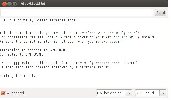
The Arduino should now print out an info menu with instructions on how to use the sketch. We’re now ready to configure the WiFly to connect to a network.
Please note that you will need to use this sketch a lot when working with your WiFly Shield. Anytime this tutorial references talking to the WiFly module, assume that it is referring to using this sketch to do so.
Troubleshooting
If you are experiencing problems with you WiFly Shield, make sure you are using the most up to date version of the library from GitHub. The Arduino IDE is constantly evolving, and, occasionally, the newest version might not work with existing libraries. If you can't get the WiFly shield to work with the latest version of the Arduino IDE, you may have to revert to an older version of the IDE. If you are using Arduino 0023 or older, you will want to use the pre-Arduino 1.0 version of the library.
If you are seeing data that looks mostly right but is jumbled in places when you use the terminal sketch, the problem is most likely related to not having the correct library matched up with the correct version of the IDE.
Connecting to a Network
The WiFly module is configured by sending it commands through its UART. To do this, the user must first place the module in command mode. For a complete list of configuration commands, please see the RN-131 Reference Guide.
To begin, put the module in command mode by typing the command
$$$
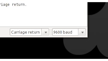
into the Arduino Serial Monitor and pressing enter. (Make sure the serial monitor is set to "No line ending" when you type in the $$$). The module will respond with the letters “CMD”, indicating that it is in command mode. From this point on, commands that we send must be ended with a carriage return, so in the dropdown menu next to the baud rate menu, select “Carriage return”. This will ensure that the serial monitor sends a carriage return after every command you type in the send box.
Next, we need to scan for wifi networks. To do this type the command
scan
You can skip this step if you already know the credentials of your wireless network. The WiFly module will scan for any networks and print the results to the terminal. We are concerned with the columns labeled “SSID” and “Sec”. These are the name of the access point and the security protocol of the access point, respectively. We will need them to configure the WiFly to connect to the access point.
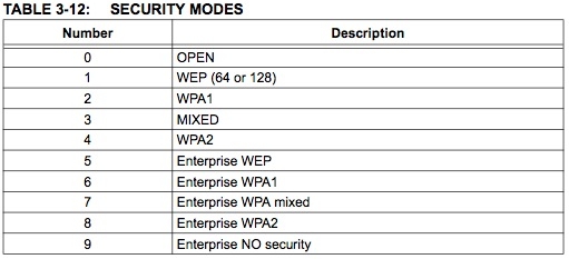
At this point, we’ll need to tell the WiFly what security protocol to use. The security protocols have set values listed in the RN131 reference guide on page 65.
Find the value that corresponds to the security protocol on your access point. Then, in the serial monitor, send the command
set wlan auth <value>
where \
If your access point is using a security protocol, you will need to tell the WiFly your passphrase. To do this, send the command
set wlan phrase <passphrase>
where \
Now our module should be configured and ready to connect to the access point. Tell it to join by sending the command
join <ssid>
Where \
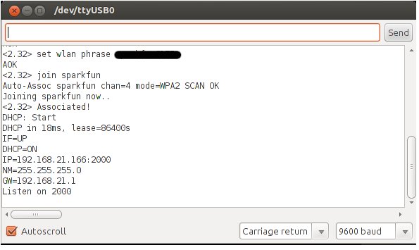
Congrats, you are now networking from the Arduino!
Autoconnect to a Network
If you would like the WiFly module to automatically connect to a network upon power up, follow the above directions. Instead of using the join command, you can store the SSID and tell the module to connect to that SSID by default.
Do so by using this command
set wlan ssid <ssid>
where \
set wlan join 1
This tells the module to try and connect to the SSID stored in memory automatically.
The last thing is to store these settings in the WiFly's config file. We'll talk about this more in depth in the Configuration Files and Firmware Upgrade section, but, for now, just know that is where the WiFly stores all its settings. To do this, simply type
save
Now, whenever you power up your WiFly, it should connect to that network without having to issue it any commands. To join to the network you just stored in memory without reseting the Arduino, issue just the join command without an parameters.
Static IP
If you want your WiFly Shiled to have a static IP address instead of having one assigned via DHCP, you must first turn of DHCP and then set the IP address you want if it hasn't been set already. Using the Terminal sketch, enter command mode. Issue this command to turn of DHCP:
set ip dhcp 0
Next you can assign the IP address you want using this command:
set ip address <address>
Troubleshooting
If you already used the WiFly shield with DHCP on, there may already be an IP address stored in the WiFly's memory. You can keep this IP address as you static IP address, and you know that it will be available.
If you upload any of the default example sketches that come with the WiFly library, you may overwrite the settings you just configured. If you are using an example sketch with a static IP, comment out the following lines in the Setup() function.
if (!WiFly.join(ssid, passphrase)) { while (1) { // Hang on failure. } }
This will prevent the sketch from overwriting your settings.
Also, check out the Configuration Files section of this tutorial to see how you can save and load different settings profiles in case you do accidentally overwrite your settings.
You may also need to change this line in any example sketch, if you plan on using a port other than 80.
WiFlyServer server(80);
Communicating with the Network
Now that the WiFly is connected, we’d like to communicate with the network. But how? What do we send? Where do we send it? The WiFly will transmit anything it’s sent, the trick to successful networking is knowing where the data is going and how to package it.
When the WiFly connects to an access point, it communicates through a port. Ports are like sub-addresses, they indicate what type of information is being sent or received so that devices know how to use the sent data. For example, when trying to reach a website, a browser communicates on port 80, which is the HTTP port (hence the “http://” at the beginning of most URLs). The server “listens” on port 80, and when a browser request comes in, it sends the requested information back on port 80. There are thousands of port numbers, each with a different standardized protocol.
By default, the WiFly transmits and listens on port 2000. We can change the port by sending the command
set ip local <port>
Where \
set ip local 80
Now, any computer that is also connected to the same access point as the WiFly can query the WiFly through a browser. Simply open a browser and attempt to navigate to
http://<IP of WiFly>
The IP address of the WiFly is always printed when it joins a network, and you can always find it by sending the command
get ip
when the device is in command mode.
When the WiFly receives a request from a browser, it will print the incoming data to the terminal. For example:
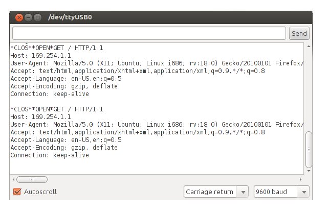
The browser is now waiting for data, the WiFly can send sensor values, serve web pages, or any other data straight back to the browser! In this case, the browser is waiting for a web page. If the WiFly responds with an HTML-formatted page, the browser will display it. The next section will show you exactly how to do that.
Setting Up a Simple Server
In this example, you will create a simple server with your WiFly module. The functionallity will be simple, but you can take what you learn with this example to create more complex projects.
Materials Needed
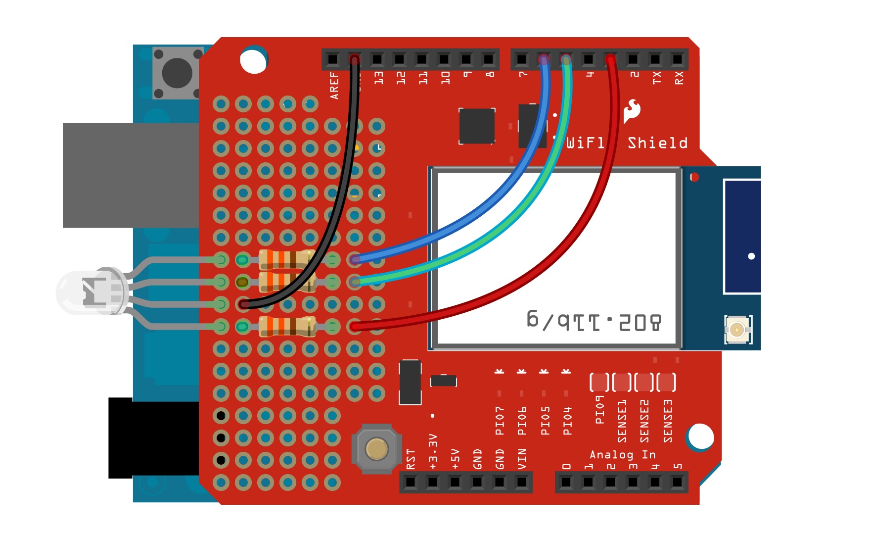
If you've been following along, you should already have a WiFly shield attached to an Arduino. For this example, the only other items you will need are an RGB LED and three 330Ω resistors. You will also need some wire or other means to connect the LED to the WiFly Shield.
Assembly
In this example, the LED and resistors will be soldered directly to the shield. If you need a refresher on soldering, check out our tutorial. For those who don't want to solder to their shield, you can use a breadboard to build the circuit.
Connect the LED and resistors to the shield like the image below. When working with a prototyping surface, don't forget that none of the through-holes are connected to one another. You must make solder connections on the underside of the shield to complete the circuit.
Firmware
Once the hardware is wired up, it's time to upload the code. Copy the code below, and upload it to your Arduino, or you can download the sketch here. Note: Keep in mind that you must have gone through the previous steps to configure your WiFly module to connect to your network automatically.
language:c
/*********************************************************
WiFi LED Controller
Joel Bartlett
SparkFun Electronics
August 1, 2013

This code uses an Arduino Uno with a SparkFun WiFly shield attached
to act as a webserver cabable of controlling an RGB LED

To use this code with Arduino 1.0+, it is recommended that you use
the latest version of the WiFLy Library found here:
https://github.com/sparkfun/WiFly-Shield
Many thanks to Philip Lindsay (aka Follower) for creating this library
and many thanks to jmr13031 for updating the library for Arduino 1.0+

This code borrows heavily from the code found from Upverter.com
https://gist.github.com/1201213
Many thanks to Emmanuel DeVries for doing a lot of the heavy lifting.

This also borrows from the Sparkfun Speakjet Wifly Example by Chris Taylor
https://www.sparkfun.com/tutorials/158
***********************************************************/
//I took out the credentials.h file as well as the code that
//tells the wifly server the ssid and the parephrase since
//this info was setup manually on the WiFly shield.
//The IP address is also set maually instead of being assigned.

#include <SPI.h>
#include "WiFly.h" //include the WiFly experimental library

char msg[128];//variables for reading in the html responses
int letterCount = 0;

int redPin = 3;
int greenPin = 5;
int bluePin = 6;

WiFlyServer server(80);// This is set manually but this line is needed to initialize server()
                  //Port 80 is the default HTTP port

///////////////////////////////////////////////////////////////////
void setup()
{
  pinMode(redPin, OUTPUT);  //set RGB pins as outputs
  pinMode(greenPin, OUTPUT);
  pinMode(bluePin, OUTPUT);

  digitalWrite(redPin, LOW); //set all LEDS to LOW/OFF
  digitalWrite(greenPin, LOW);
  digitalWrite(bluePin, LOW);

   WiFly.begin();//begin WiFly communictaiosn

  Serial.begin(9600);  //Serial communication at 9600 buad for debugging
  Serial.print("IP: ");
  Serial.println(WiFly.ip());  //Prints IP address once associated with the network
                              //If DHCP is on, this IP can change. If static IP is set, it should not.

  server.begin(); //initialize the server
}
///////////////////////////////////////////////////////////////////
void loop()
{
  WiFlyClient client = server.available();
  //the flag dataFlag give a notification of where the actual post
  //is once we flag it we can begin recording the message
  //so we can do stuff with it later on

  int dataFlag = 0;
  int msgIsolator = 0;

  //int inChar; //variable for reading in data from the phone/browser
  //boolean isParsing = false;// flag for reading in and parsing data

  if (client) {
    // an http request ends with a blank line
    boolean current_line_is_blank = true;
    boolean endOfCode = true;
    char c;

    while (client.connected())
    {
      if (client.available())
      {
        c = client.read();
        delay(10);
        //Uncomment this line to see the HTTP respone
        Serial.print(c);

        // if we've gotten to the end of the line (received a newline
        // character) and the line is blank, the http request has ended,
        // so we can send a reply
        if (!client.available()) {
          endOfCode = true;
        } else if (c == '\n') {
          // we're starting a new line
          current_line_is_blank = true;
        } else if (c != '\r') {
          // we've gotten a character on the current line
          current_line_is_blank = false;
          endOfCode = false;
        }

        //this is where the message that the user entered is going so this is where
        //we record it into a char array
        if (msgIsolator == 1)
        {
          recordMessage(c);
          delay(100);
        }

        if ((c == '\n' && current_line_is_blank && !client.available()) || endOfCode)
        {

          //As soon as the page has been refreshed the letter count is set to zero
          letterCount = 0;

          //Once the page has been refreshed we are no longer on the first run through
          //off the program so we set this to false
          endOfCode = false;

          // send a standard http response header
          client.println("HTTP/1.1 200 OK");
          client.println("Content-Type: text/html");
          //client.println("Connection: close");

          client.println();

          //This basically creates what the user will see on the site.
          client.println("<html>");
          client.println("<title>RGB LED Server</title>");

          //the form code creates the buttons to click and change the temp/blanketstate
          client.println("<center>");
          client.println("<form name=\"input\" action=\"\" method=\"post\">");
          client.println("<input type=\"submit\" name=\"%\" value=\"Red\" style=\"height:50px; width:150px\" >");// I made the buttons larger for smart phone screens
          client.println("</form>");

          client.println("<form name=\"input\" action=\"\" method=\"post\">");
          client.println("<input type=\"submit\" name=\"%\" value=\"Green\" style=\"height:50px; width:150px\" >");
          client.println("</form>");

          client.println("<form name=\"input\" action=\"\" method=\"post\">");
          client.println("<input type=\"submit\" name=\"%\" value=\"Blue\" style=\"height:50px; width:150px\" >");
          client.println("</form>");

          client.println("</center>");
          client.println("</html>");
          //***NOTE: I originally added the Reload button, and it broke everything. I combined the temperature state and number into one line and
          //took out some other html code. It then worked. This leads me to beleive that there is only so much that the WiFly can serve up at a time??***
          delay(500);//delay is very important. It gives the browser time to process requests
          letterCount = 0;
          checkAction();//go to check action function is a HTML button is pressed.
          break;
        }

        //if you want to see all data comming in and going out uncomment the line below
        //Serial.print(c);

        //We detect where the actual post data is in other words what the user entered
        //once we isolate it we can parse it and use it
        if (c =='%')
        {
          dataFlag = 1;
        }
          if (dataFlag == 1)
          {
            //in here goes the user entered data it follows the string "25="
            if (c == '=')
            {
              //trim the fat of the soon to be recorded char so we only get the user entered message
              msgIsolator = 1;
            }
          }
      }
    }

  // give the web browser time to receive the data
  delay(100);//delay is very important
  client.flush();
  client.stop();
  }
}
///////////////////////////////////////////////////////////////////////

char recordMessage (char incomingMsg)
{
  //letterCount = 0;
  msg[letterCount] = incomingMsg;
  letterCount++;
  delay(100);
}
///////////////////////////////////////////////////////////////////////
void checkAction()
// the first two or three letters of each message are read to determine which button was clicked on the webage
{
  if (msg[0] == 'R' && msg[1] == 'e' && msg[2] == 'd')// Turn on RED LED
  {
    digitalWrite(redPin, HIGH);
    digitalWrite(greenPin, LOW);
    digitalWrite(bluePin, LOW);
  }
  //-------------------------------------------------------
  else if (msg[0] == 'G' && msg[1] == 'r' && msg[2] == 'e')//Turn on GREEN LED
  {
    digitalWrite(redPin, LOW);
    digitalWrite(greenPin, HIGH);
    digitalWrite(bluePin, LOW);
  }
  //-------------------------------------------------------
  else if (msg[0] == 'B' && msg[1] == 'l' && msg[2] == 'u')//Turn on BLUE LED
  {
    digitalWrite(redPin, LOW);
    digitalWrite(greenPin, LOW);
    digitalWrite(bluePin, HIGH);
  }

}//end checkAction()
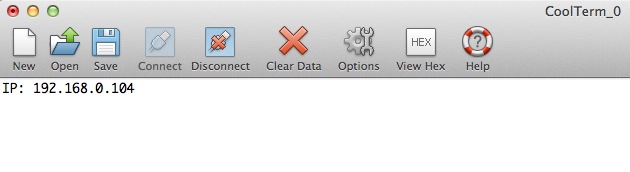
Once the code is uploaded, open the Serial Terminal set to 9600. After a few seconds, the WiFly should print out its IP address. This will vary depending on if you are using DHCP or if you assigned a static IP.
In your browser, type the IP address that was printed out in the Terminal into the address bar. After a few seconds, you should see a web page with these three buttons load.

As long as everything is connected correctly, each button on the website should light up the corresponding LED when clicked. The change will not be instantaneous as the commands need to propagate from the browser, through the network, and to your WiFly shield.
You can even control it from your smart phone as long as it's connected to the same wireless network as the WiFly shield.

Troubleshooting
- Please note that data transmission of the wireless network is NOT instantaneous. It may take up to several seconds for your request to be sent to and processed by the Wifly shield depending on the size and configuration of your wireless network. If you are experiencing problems, there are many links in the chain to investigate.
It is also worth noting that the sketch prints data to the terminal by default. This will add some time to this delay. You can change this by commenting/uncommenting line 88.
if (client.available())
      {
        c = client.read();
        delay(10);
        //Uncomment this line to see the HTTP respone
        //Serial.print(c);
When you click any of the HTML buttons, you should see the green LED on the WiFly shield go solid while it processes the request. If you see that the LED is just hanging and never returns to blinking, then the WiFly shield is getting hung up on the HTML request. This could be the result of a firmware issue or a network/browser issue.
If the red or yellow LED on the WiFly shield are blinking continuously, it is having a problem connecting to your wireless network. See the datasheet for more info on LED statuses.
If you have a steady blinking green LED and your Arduino is printing out a valid IP address but you are not seeing a webpage load, then the problem is most likely in the code or in your wireless network settings. Makes sure you selected the correct security settings and make sure you save your settings to the WiFly config file after you have set all the necessary settings.
Going Further
Try changing up the code to add different colors and more buttons. You can also take a look at the server example that comes with the WiFly library. This example reads the analog inputs on the Arduino and posts them to a webpage. See if you can add digital inputs and analog outputs to the same webpage. You could also replace the single RGB LED with a strip of RGB LEDS controlled via some MOSFETs. Then you could create an Internet controlled LED Light Cube
Configuration Files and Upgrading the Firmware
The firmware for the WiFly module is updated occasionally. Luckily for you, there is a simple way to update your module to the latest version.
The WiFly module sold by SparkFun Electronics currently ships with firmware version 2.38. To check which version of the firmware your WiFly shield is running, upload the Terminal sketch, enter command mode, and enter this command:
ver
Note: The version is usually displayed after each command issued in command mode as well.
Before we update the firmware, let's go over the configuration files stored within the WiFly and how to add other config files.
Storing Separate Configuration Files
Using the terminal sketch mentioned on the WiFly Library page, create a connection to the module, and enter command mode.
Now issue the command
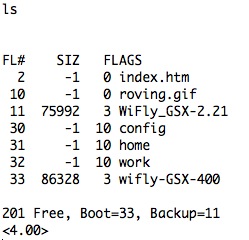
ls
to list all the files on the module. Depending on what firmware version you have, you should see something like this:
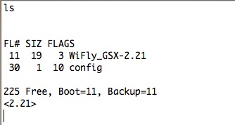
You'll notice the WiFly_GSX-2.21 file is the current firmware version and the config file is where all of the settings are stored.
One great feature of the WiFly is its ability to store multiple configuration files. For instance, if you wanted to use the WiFly at both your home and your work, you could create two separate config files, each with the correct settings for both locations. To do so, set all the settings for one location such as SSID, pasphrase, security. etc. Then use the save command followed by the name you want to call that configuration.
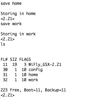
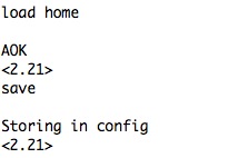
Now, to use one of those config files, simply issue the load command followed by the name of the file. It's impotant to note that even though there are separate config files, the WiFly always uses what is stored in the default config file, so after you load a config file, it's best to save it to the default config file using just the save command.
Now, even after a firmware update, you should be able to load all of the settings you had before. (Note: Firmware updates will often include new features/settings, so there is no guarantee that your previous settings will work on a new version of the firmware.) You can delete a config file using the del
Updating the Firmware
Directions on how to update the firmware can be found on Microchip site, but we will also go over the process here.
Again, use the terminal sketch to enter command mode. You must be connected to the Internet in order to get the firmware update from Roving Networks, so follow the directions on the Connecting to a Network page to connect to your wireless network.
While you are connected, you should still be able to issue commands. We now need to set the FTP settings on the module and point it to the correct website from which to retrieve the new firmware. Depending on 1) how old your module is and 2) how many settings you have changed, you may need to change several settings.
The first thing to check/change is the FTP settings. Issue the command
get f
to see your current FTP settings.
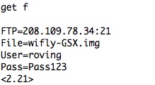
To get the update, you must make sure the FTP address is the correct one. The Roving Networks page say the the firmware must be pulled from rn.microchip.com. Pinging this URL gives the correct IP address.

Now, set the FTP address to the one returned during the ping, if it does not match the one stored in memory. Also make sure the user name and password match the ones in the image below. These should be the default values unless you changed them in your configuration.
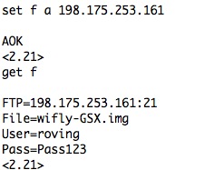
With all the correct settings, issue this command
ftp update
You should see something like this:
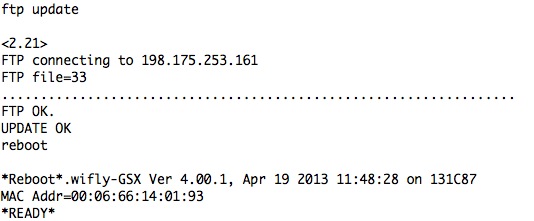
Once the update has finished, you need to reboot the module, give it a factory RESET, and then reboot it again.
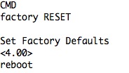
Failing to issue the factory RESET will result in config files not being saved correctly.
Now, using the ls command, we can see the new firmware. The old firmware is still stored in the module in case you need to revert back to an older version.
To boot from an older firmware version, use the boot image
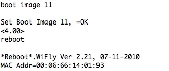
Again, it's best to reboot, RESET, and reboot after changing the firmware.
As of this writing, the most up to date version of the firmware that will be downloaded with this process is Ver 4.41.
Troubleshooting
If you can't get the firmware to update, check the following:
- Make sure you are actually connected to the Internet.
- Make sure the FTP address is correct (198.175.253.161).
- Make sure the FTP port is correct (21).
- Make sure the FTP User=roving and the Pass=Pass123
- If all else fails, issue a factory RESET and then try updating the firmware.
Resources and Going Further
This is just the basc hookup of the WiFly Shield. The shield works very well as a host or client. To use it as a host, many projects also include an SD Shield to hold large amounts of data to be served, rather than save them on the Arduino chip.
Check out the other examples you downloaded with the WiFly Shield library. There are some great web client and server examples as well as a lot of other great info on using the shield
To get the most out of your shield, be sure to read the reference guides and datasheets. Here are links to all the most important ones.
- RN131 Product Page
- RN131 Reference Guide
- [RN131 Datasheet](link text
- [SC16IS750 SPI to UART Bridge Datasheet](link text
For more examples of what the WiFly is capable of, check out these projects: