WiFi Controlled Robot
 Alex the Giant
Hardware Hookup
The first step is assembling the hardware. To get started, assemble the shadow chassis. You can find detailed instructions in this guide:
All that's needed for this tutorial is assembling the chassis and mounting the motors.
Assembling the Electronics
To assemble to electronics, use the schematic below:
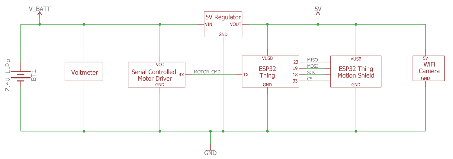
It's good practice to do a few sanity checks as you put this together.
Start with the battery connections and build up to the 5V DC/DC converter. Once the DC/DC converter is in place, measure the output voltage and make sure you're seeing close to 5V.
Schematic Overview
Power is supplied from the 7.4V (2-Cell) Lipo battery. Running Lipo batteries down below a safe voltage (3V per cell, or 6V in this case) can cause damage to the battery which can cause it to fail or shorten the life of the battery. To make sure we don't run our battery flat, we'll use a panel voltmeter to monitor the battery's voltage. At 6V, the battery is considered flat, and needs to be recharged. According to the DC/DC converter's datasheet, the regulator has an input voltage range of 7-28VDC, but in my testing the regulator will work as low as 6.5V. Below this input voltage, the regulator will output 0VDC, so you will need to change the battery when the output voltage drops below 6.5V.
The raw battery voltage is also directly fed into the Serial Controlled Motor Driver (SCMD), which can handle up to 11V to drive the motors. The SCMD can run off 5V, but with a lower voltage the motors will draw less current, which will extend battery life, but have less torque and move slower.
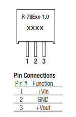
To power the ESP32 Thing, Motion Shield, and Camera, we'll need to regulate the battery's voltage down to 5V. To do that we'll use a 5V DC/DC converter which has 3-pins: VIN, GND, VOUT (see pinout above). VIN is the battery voltage which should be between 6 and 8.4V, VOUT is 5.0V, and GND is GND. The DC/DC converter is recommended over a standard LM7805, because it is more efficient than a linear regulator and extends the battery life. With a linear regulator the wasted power is converted to heat, and with the ESP32 and camera drawing around 500mA of current, a linear regulator (such as the LM7805) would be hot to the touch.
For signal wires, most of the data signals are connected when you plug the Motion Shield into the ESP32. The only signal wire that will need to be soldered is the TX pin of the ESP32 to the SCMD. When everything is soldered together, it should look like this:

Wire Color Code:
- YELLOW: Battery Voltage
- BLACK: Ground
- BLUE: 5.0V
- GREEN: Signal
Motor Connections:
- Left Motor+ (RED): SCMD A2
- Left Motor- (BLACK): SCMD A1
- Right Motor+ (RED): SCMD B2
- Right Motor- (BLACK): SCMD B1