WiFi Controlled Robot
 Alex the Giant
Introduction
This tutorial will show you how to build an Internet controlled robot with a live video stream to a custom site hosted by the ESP32 Thing. With a little hacking you can customize the robot to create your own pan/tilt camera or even a Nerf Sentry Gun that can be remotely controlled!
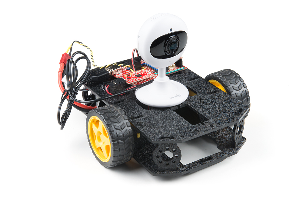
This project is based around the Shadow Chassis, which is controlled by the ESP32 Thing and the Serial Controlled Motor Driver.
Required Materials
To build this project, you will need the following:
Not included in the wishlist is a WiFi camera that you will need to source. When picking a camera, keep a few things in mind:
- Power supply voltage: Ideally the camera can be powered from USB, so that the ESP32 and camera can share the same 5V rail.
- 2.4GHz WiFi connection: So that the ESP32 and camera can share the same network.
- Framerate: Higher is better. The best I was able to find was 30 frames per second, but due to real world conditions, expect it to be around half of what is outlined in the technical details.
- Accessible with an HTTP link: For this you'll have to do some googling, but if you type in the manufacturer and model number followed by "URL" (e.g. "Wansview 1080p URL") you should find a link that will show you what to put in the address bar of your browser to view the video stream. We'll discuss how to use that URL in the camera testing section.
Suggested Reading
Before starting this project, there may be a few subjects you'll want to be familiar with before starting this project.
How to Solder: Through-Hole Soldering
Serial Communication
Installing an Arduino Library
Assembly Guide for RedBot with Shadow Chassis
ESP32 Thing Hookup Guide
Serial Controlled Motor Driver Hookup Guide
ESP32 Thing Motion Shield Hookup Guide
Hardware Hookup
The first step is assembling the hardware. To get started, assemble the shadow chassis. You can find detailed instructions in this guide:
All that's needed for this tutorial is assembling the chassis and mounting the motors.
Assembling the Electronics
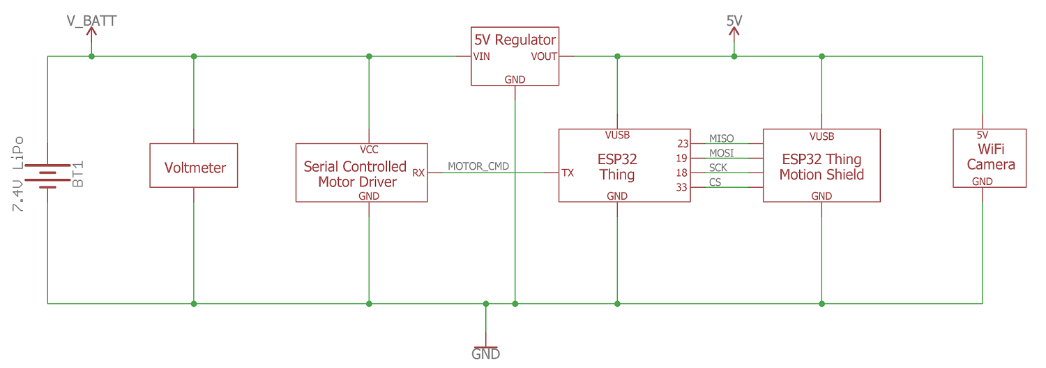
To assemble to electronics, use the schematic below:
It's good practice to do a few sanity checks as you put this together.
Start with the battery connections and build up to the 5V DC/DC converter. Once the DC/DC converter is in place, measure the output voltage and make sure you're seeing close to 5V.
Schematic Overview
Power is supplied from the 7.4V (2-Cell) Lipo battery. Running Lipo batteries down below a safe voltage (3V per cell, or 6V in this case) can cause damage to the battery which can cause it to fail or shorten the life of the battery. To make sure we don't run our battery flat, we'll use a panel voltmeter to monitor the battery's voltage. At 6V, the battery is considered flat, and needs to be recharged. According to the DC/DC converter's datasheet, the regulator has an input voltage range of 7-28VDC, but in my testing the regulator will work as low as 6.5V. Below this input voltage, the regulator will output 0VDC, so you will need to change the battery when the output voltage drops below 6.5V.
The raw battery voltage is also directly fed into the Serial Controlled Motor Driver (SCMD), which can handle up to 11V to drive the motors. The SCMD can run off 5V, but with a lower voltage the motors will draw less current, which will extend battery life, but have less torque and move slower.
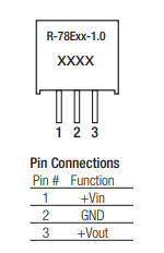
To power the ESP32 Thing, Motion Shield, and Camera, we'll need to regulate the battery's voltage down to 5V. To do that we'll use a 5V DC/DC converter which has 3-pins: VIN, GND, VOUT (see pinout above). VIN is the battery voltage which should be between 6 and 8.4V, VOUT is 5.0V, and GND is GND. The DC/DC converter is recommended over a standard LM7805, because it is more efficient than a linear regulator and extends the battery life. With a linear regulator the wasted power is converted to heat, and with the ESP32 and camera drawing around 500mA of current, a linear regulator (such as the LM7805) would be hot to the touch.
For signal wires, most of the data signals are connected when you plug the Motion Shield into the ESP32. The only signal wire that will need to be soldered is the TX pin of the ESP32 to the SCMD. When everything is soldered together, it should look like this:

Wire Color Code:
- YELLOW: Battery Voltage
- BLACK: Ground
- BLUE: 5.0V
- GREEN: Signal
Motor Connections:
- Left Motor+ (RED): SCMD A2
- Left Motor- (BLACK): SCMD A1
- Right Motor+ (RED): SCMD B2
- Right Motor- (BLACK): SCMD B1
Motor Wiring Test
Note: This example assumes you are using the latest version of the Arduino IDE on your desktop. If this is your first time using Arduino, please review our tutorial on installing the Arduino IDE. If you have not previously installed an Arduino library, please check out our installation guide.
Now that we have the robot put together, let's add some code! But before we get ahead of ourselves, let's test to make sure everything is working. The first thing we want to do is make sure the motors are working correctly. What we're looking for is that when we send a command, the wheels move in the correct direction. Specifically:
- Forward: Both wheels spin forward
- Reverse: Both wheels spin in reverse
- Left: Left wheel spins in reverse, right wheel spins forward
- Right: Left wheel spins forward, right wheel spins in reverse
If you haven't uploaded code to an ESP32 before, check out the hookup guide to learn how to program the ESP32 Thing in Arduino.
Once you have the board definitions installed, upload the following sketch to your ESP32:
language:cpp
/*
 * Alex Wende SparkFun Electronics
 * ESP32 Motor Wiring Test
 *
 * In this example we'll send motor commands to the Serial Controlled Motor Driver (SCMD)
 * to see how the motors respond based on the commands we send.
 *
 * Commands used:
 * "D\r\n" - Sends a disable command to stop the motors
 * "E\r\n" - Sends a enable command to turn the motors on
 * "M0F50\r\n" - Tells the motor driver to spin motor 0 forwards at 50% power
 * "M1R100\r\n" - Tells the motor driver to spin motor 1 in reverse at 100% power
 */

byte counter = 0;

void setup()
{
  Serial.begin(9600); // Initialize serial port to the SCMD's default baud rate
  delay(500);         // Wait a bit to make sure the SCMD is ready
}

void loop()
{
  if(counter == 0)
  {
    Serial.println("Sending Forward Command:");
    delay(50);
    Serial.print("D\r\n");
    delay(50);
    Serial.print("M0F50\r\n");
    delay(50);
    Serial.print("M1F50\r\n");
    delay(50);
    Serial.print("E\r\n");
  }
  else if(counter == 1)
  {
    Serial.println("Sending Reverse Command:");
    delay(50);
    Serial.print("D\r\n");
    delay(50);
    Serial.print("M0R50\r\n");
    delay(50);
    Serial.print("M1R50\r\n");
    delay(50);
    Serial.print("E\r\n");
  }
  else if(counter == 2)
  {
    Serial.println("Sending Left Command:");
    delay(50);
    Serial.print("D\r\n");
    delay(50);
    Serial.print("M0R50\r\n");
    delay(50);
    Serial.print("M1F50\r\n");
    delay(50);
    Serial.print("E\r\n");
  }
  else
  {
    Serial.println("Sending Right Command:");
    delay(50);
    Serial.print("D\r\n");
    delay(50);
    Serial.print("M0F50\r\n");
    delay(50);
    Serial.print("M1R50\r\n");
    delay(50);
    Serial.print("E\r\n");
  }

  counter++;
  if(counter > 3)
  {
    counter = 0;
  }
  delay(5000);
}
Once the code has uploaded, open up your serial terminal. Make sure the baud rate is set to 9600, and you should see messages like this:
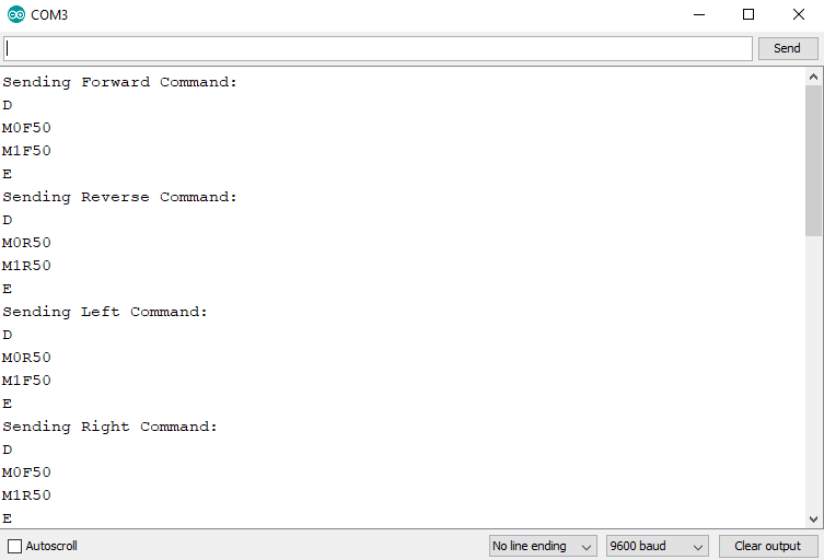
Pay attention the messages stating which command was sent, and verify that what was sent reflects what happened. If nothing moves, make sure you have power connected correctly and your motors are connected to the SCMD, and that you set the baud rate to 9600 in your Arduino sketch (not just in the terminal window). If one (or both) motors spins in the opposite direction than it should, you can fix it by swapping the motor connections to the SCMD.
Another option is to correct it in software. If the forward command was sent but motor0 spins in reverse, replace M0F50\r\n with M0R50\r\n. Another possibility is if the forward/reverse commands work, but the left/right commands are backwards, swap the M0 and M1 in the left and right command blocks. If you need to make changes in the software, remember which ones need to be changed when we add code to the final example.
Controlling the Motors From a Web Page
Now that we know the motors are working correctly, we'll next try to control them from a web page hosted by the ESP32 Thing. To do this, we'll load the Arduino code on to the ESP32. Copy and paste the following code into Arduino and upload it to the board. All of the libraries come with Arduino and the ESP32 bootloader core except for ESP32WebServer.h which you can download from the link below:
language:cpp
/*
 *  Alex Wende SparkFun Electronics
 *  ESP32 Web Controlled Motor Test
 *
 *  To use this code, download the ESP32WebServer library from:
 *  https://github.com/Pedroalbuquerque/ESP32WebServer
 *
 *  In this Example we'll use the arrow keys from our keyboard to send commands to the Serial
 *  Controlled Motor Driver. When the ESP32 connects to the WiFi network, the ESP32 sends the
 *  IP address over the Serial to the terminal window at 9600 baud. Copy and paste the IP
 *  address into your brower's window to go to the ESp32's web page. From there, use the arrow keys
 *  to control the motors.
 *
 *  UP Arrow - Drive Forward
 *  DOWN Arrow - Drive in Reverse
 *  LEFT Arrow - Turn Left
 *  RIGHT Arrow - Turn Righ
 *
 *  If the motors aren't spinning in the correct direction, you'll need to to change the motor
 *  number and/or motor direction in the handleMotors() function.
 */

#include <WiFiClient.h>
#include <ESP32WebServer.h>
#include <WiFi.h>
#include <SPI.h>
#include <SD.h>

const char* ssid = "*************";
const char* password = "*********";

ESP32WebServer server(80);  //Default port number

void handleRoot()
{
  /* we load the index.html from microSD */
  File myFile = SD.open("/index.html");
  if (myFile)
  {
    /* respond the content of file to client by calling streamFile()*/
    size_t sent = server.streamFile(myFile, "text/html");
    /* close the file */
    myFile.close();
  }
  else
  {
    Serial.println("error opening index.html");
  }
}

//XML page to listen for motor commands
void handleMotors()
{
  String motorState = "OFF";
  String t_state = server.arg("motorState"); //Refer  xhttp.open("GET", "setMotors?motorState="+motorData, true);

  Serial.print("D\r\n"); //Disable motors
  delay(50);

  if(t_state.startsWith("U"))  //Drive Forward (UP Arrow)
  {
    Serial.print("M0F70\r\n");
    delay(50);
    Serial.print("M1F70\r\n");
    delay(50);
    Serial.print("E\r\n");
  }
  else if(t_state.startsWith("D")) //Reverse (DOWN Arrow)
  {
    Serial.print("M0R70\r\n");
    delay(50);
    Serial.print("M1R70\r\n");
    delay(50);
    Serial.print("E\r\n");
  }
  else if(t_state.startsWith("R")) //Turn Right (Right Arrow)
  {
    Serial.print("M0F50\r\n");
    delay(50);
    Serial.print("M1R50\r\n");
    delay(50);
    Serial.print("E\r\n");
  }
  else if(t_state.startsWith("L")) //Turn Left (LEFT Arrow)
  {
    Serial.print("M0R50\r\n");
    delay(50);
    Serial.print("M1F50\r\n");
    delay(50);
    Serial.print("E\r\n");
  }

   server.send(200, "text/plain", motorState); //Send web page
}

// cannot handle request so return 404
void handleNotFound()
{
  server.send(404, "text/plain", "File Not Found\n\n");
}

void setup(){
  Serial.begin(9600); //SCMD + debug messages
  WiFi.begin(ssid, password); //WiFi network to connect to

  Serial.println();

  // Wait for connection
  while (WiFi.status() != WL_CONNECTED) {
    delay(500);
    Serial.print(".");
  }
  Serial.println("");
  Serial.print("Connected to ");
  Serial.println(ssid);
  Serial.print("IP address: ");
  Serial.println(WiFi.localIP());

  /* register the callbacks to process client request */
  /* root request we will read the memory card to get
  the content of index.html and respond that content to client */
  server.on("/", handleRoot);
  server.on("/setMotors", handleMotors);
  server.onNotFound(handleNotFound);
  server.begin(); //Start the web server

  Serial.println("HTTP server started");
  Serial.print("Initializing SD card...");

  /* initialize microSD */
  if (!SD.begin(33)) {
    Serial.println("initialization failed!");
    return;
  }
  Serial.println("initialization done.");
}

void loop(){
  server.handleClient();
}
The Arduino code doesn't include any of the HTML code that your browser needs to display the web page. For that we'll need to load the HTML file on to a microSD card. You could also directly load the HTML code into the handleRoot() function, but by keeping the HTML code on a microSD card, we can eject the SD card and change the code, faster than it would take to recompile the ESP32 code and re-upload it to the board.
To put the code on the SD card, we'll plug the card into our computer and create a file called "index.html", which will have the following code saved to that file:
<!DOCTYPE html>
<html>
    <head>
        <meta charset="UTF-8">
        <title> Web Server Motor Control Test </title>
        <script type="text/javascript">
            var sendCommand = 1;

            //Key Pressed
            document.addEventListener("keydown", function (evt) {
                if (evt.keyCode == "38" && sendCommand) {   // up arrow
                    sendData("U")
                    sendCommand = 0;
                }
                else if (evt.keyCode == "40" && sendCommand) {  // down arrow
                    sendData("D")
                    sendCommand = 0;
                }
                else if (evt.keyCode == "37" && sendCommand) {  // left arrow
                    sendData("L")
                    sendCommand = 0;
                }
                else if (evt.keyCode == "39" && sendCommand) {  // right arrow
                    sendData("R")
                    sendCommand = 0;
                }
            });

            //Key Released
            document.addEventListener("keyup", function (evt) {
                if(evt.keyCode == "37" || evt.keyCode == "38" || evt.keyCode == "39" || evt.keyCode == "40") {
                    sendData("STOP");
                    sendCommand = 1;
                }
            });

            function sendData(motorData) {  //Send data for ESP32 to resond to
                var xhttp = new XMLHttpRequest();
                xhttp.onreadystatechange = function() {
                    if (this.readyState == 4 && this.status == 200) {
                    }
                };
                xhttp.open("GET", "setMotors?motorState="+motorData, true);
                xhttp.send();
            }
        </script>
    </head>
    <body>
        <h2>SparkFun ESP32 Thing Motor Control Test</h2>
        <ul>
            <li>Use the arrow keys send commands to the motors.</li>
            <li>When a arrow key is pressed, this page sends a XML request for the ESP32 to respond to.</li>
            <li>The ESP32 responds by sending a motor command to the Serial Controlled Motor Driver. </li>
            <li>By sending a XML request, we're able to control the motors without having to reload the page!</li>
        </ul>
   </body>
</html>
Once you have that file saved as a .html, you can eject the SD card and plug it into the Motion Shield and open the your terminal window. You may need to press the reset button on your ESP32 Thing to view the debug messages. If all goes well you should see the following in your terminal window:
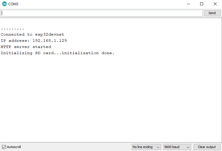
If you only see "...", it means that it's not connecting to your WiFi network. Make sure the SSID and password is correct. If the SD card failed to initialize, it could be that you forgot to plug in the SD card, or it could be that the chip select pin is incorrect. For the Motion Shield it should be GPIO pin 33.
Once the ESP32 has connected to the network, and the SD card is initialized, you can try to access the web page. Make sure your computer is on the same network as the ESP32, and enter the IP address of the ESP32 into the address bar of your browser. It should display the following page:

From this page, when you press the arrow keys you should see the motors respond. As you press the arrow keys, check to make sure the motors respond correctly to the arrow keys. If not, you'll need to modify the code in the handleMotors() function to move forward when the up arrow key is pressed, reverse when the down arrow key is pressed, and so on.
Testing the WiFi Camera
As mentioned at the end of the Introduction, you'll need to source your own WiFi camera, which makes it difficult to show you how to get image or video data from your camera into a web page, because each manufacturer will do things differently. To get started, you'll need to do some googling. Search for the manufacturer's name and the camera's model number followed by "URL" (e.g. "Wansview 1080p URL"), and you should find a link that will show you what to put in the address bar of your browser to view the video stream.
For the camera I’m using, there are two links to see what the camera sees:
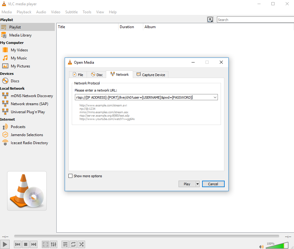
- video stream: “rtsp://[IP ADDRESS]:[PORT]/live/ch0?user=[USERNAME]&pwd=[PASSWORD]”
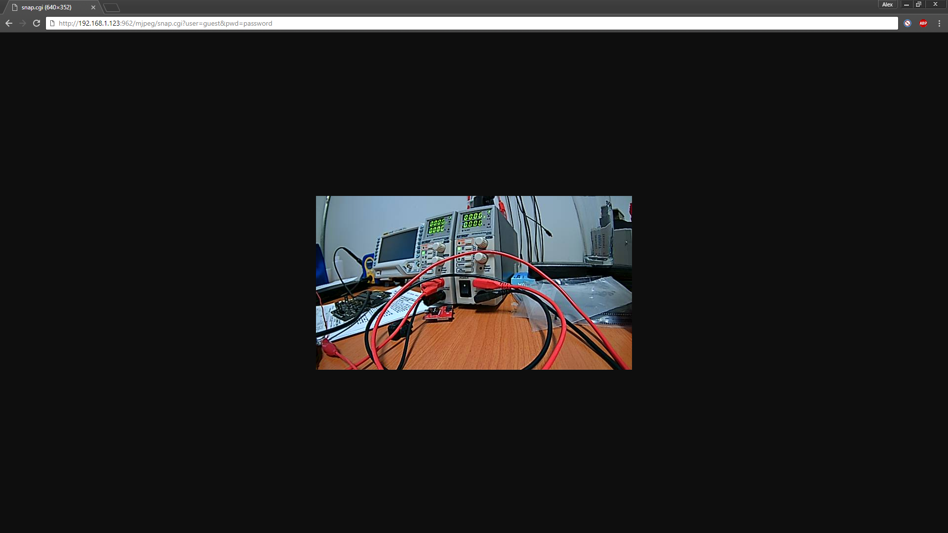
- snapshot (takes a photo of what the camera can see): “http://[IP ADDRESS]:[PORT]/mjpeg/snap.cgi?user=[USERNAME]&pwd=[PASSWORD]”.
The first URL provides the video stream using the Real Time Streaming Protocol (RTSP). If you have a video player (such as VLC) installed on your computer, you can open a network stream with the RTSP link and fill in the specific information of your camera (IP address, port number, user name and password) to view the video stream.
Unfortunately, an RTSP stream isn't native to HTML5. There are Javascript libraries which will convert the protocol to use in a <video> tag, but there's another option available which allow us to create a video if we don't need to use the camera's microphone and speaker. The second URL uses the Hypertext Transfer Protocol (HTTP) to take a single picture from the camera. With a few lines of Javascript code, we'll be able refresh the image being loaded onto the page to look like a video. You can test the link by opening your browser and entering the HTTP URL into the address bar and fill in the specific information of your camera (IP address, port number, user name, and password) to take a photo. If all goes well, you should see the photo in the browser.
WiFi Camera Robot Software
Now that the wiring works, the motors can be controlled from a web page, and we know the URL for our camera works, we can finally put it all together. All we need to do is eject the microSD card from our Motion Shield and change the HTML code on our computer.
reloadImg() Javascript function.<!DOCTYPE html>
<html>
<head>
<meta charset="UTF-8">
<script type="text/javascript">
var sendCommand = 1;
var count = 0;
document.addEventListener("keydown", function (evt) {
count = count + 1;
if(count > 10) {
count = 2;
}
if(count > 2) {
if (evt.keyCode == "38" && sendCommand) {
sendData("D1") // up arrow
sendCommand = 0;
}
else if (evt.keyCode == "40" && sendCommand) {
sendData("U1") // down arrow
sendCommand = 0;
}
else if (evt.keyCode == "37" && sendCommand) {
sendData("L1") // left arrow
sendCommand = 0;
}
else if (evt.keyCode == "39" && sendCommand) {
sendData("R1")// right arrow
sendCommand = 0;
}
}
});
document.addEventListener("keyup", function (evt) {
if(count > 2) {
if(evt.keyCode == "37" || evt.keyCode == "38" || evt.keyCode == "39" || evt.keyCode == "40") {
sendData("STOP");
sendCommand = 1;
}
count = 0;
}
else {
if (evt.keyCode == "38" && sendCommand) {
sendData("D3") // up arrow
}
else if (evt.keyCode == "40" && sendCommand) {
sendData("U3") // down arrow
}
else if (evt.keyCode == "37" && sendCommand) {
sendData("L3") // left arrow
}
else if (evt.keyCode == "39" && sendCommand) {
sendData("R3")// right arrow
}
count = 0;
sendCommand = 1;
}
});
function sendData(motorData) {
var xhttp = new XMLHttpRequest();
xhttp.onreadystatechange = function() {
if (this.readyState == 4 && this.status == 200) {
}
};
xhttp.open("GET", "setMotors?motorState="+motorData, true);
xhttp.send();
}
var refreshRate = 5; //ms
function reload()
{
setTimeout('reloadImg("refresh")',refreshRate)
};
function reloadImg(id)
{
var obj = document.getElementById(id);
var date = new Date();
obj.src = "http://[IP ADDRESS]:[PORT]/mjpeg/snap.cgi?chn=1?user=[USERNAME]&pwd=[PASSWORD]&t=" + Math.floor(date.getTime()/refreshRate);
}
</script>
</head>
<body>
<h2>SparkFun ESP32 Thing + WiFi Camera Remote Control</h2>
<img src="http://[IP ADDRESS]:[PORT]/mjpeg/snap.cgi?chn=1?user=[USERNAME]&pwd=[PASSWORD]" name="refresh" id="refresh" onload='reload(this)' onerror='reload(this)'>
<br/>
<ul>
<li>Use the arrow keys send commands to the motors.</li>
<li>When a arrow key is pressed, this page sends a XML request for the ESP32 to respond to.</li>
<li>The ESP32 responds by sending a motor command to the Serial Controlled Motor Driver. </li>
<li>By sending a XML request, we're able to control the motors without having to reload the page!</li>
</ul>
</body>
</html>
This HTML file has a few changes from the Controlling the Motors From a Web Page example. The most obvious change is the <img> tag which calls the reloadImg() function. In the reloadImg() Javascript function, we refresh the image every 5ms. In the URL of the function, we added on "&t=[Time in Milliseconds]"; without it the browser will assume it's the same image and to save time reload that image with the same image without talking to the camera. Adding on the time parameter will make the browser think it's a new URL and retrieve it instead of reloading the same image that it stored in the cached memory.
Resources and Going Further
This tutorial is based on a blog post from a few weeks back. Check it out!
Because this project is Open Source, you can expand on this project and make it your own. By adding port forwarding to your router, you could make the robot accessible from anywhere in the world if you have an Internet connection. Or maybe you want to replace the motors with servos to create your own pan/tilt camera, or even a nerf gun for a remote controlled sentry!
Or if you're looking for another project to put your ESP8266/ESP32 to work, check out some of our other great tutorials!