TFT LCD Breakout 1.8in 128x160 Hookup Guide
Introduction
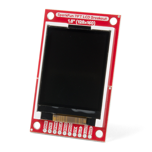
The TFT LCD Breakout 1.8in 128x160 is a versatile, colorful, and easy way to experiment with graphics or create a user interface for your project. In this guide we will familiarize ourselves with the hardware, explain how to connect the display to your microcontroller of choice, cover how to install the Arduino libraries, and give an overview of the software examples that you can start off with.
Required Materials
The TFT LCD Breakout has Plated-Through-Hole (PTH) connections. You can connect these in a number of different ways but we suggest soldering in breakaway headers for use with a breadboard. You'll also need an Arduino compatible microcontroller of your choice - we recommend something with extra RAM like the ESP32 Thing Plus or the RedBoard Turbo. You may not need everything on this wish list, depending on what you may already have. Add it to your cart, read through the guide, and adjust the cart as necessary.
Tools
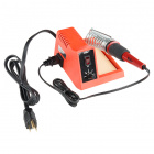
In addition to those components, you'll need a soldering iron, solder, and probably some general soldering accessories to help with the job.
Weller WLC100 Soldering Station
TOL-14228Suggested Reading
If you aren’t familiar with the following concepts, we recommend checking out these tutorials before continuing.
How to Solder: Through-Hole Soldering
Installing an Arduino Library
Serial Peripheral Interface (SPI)
Everything You Should Know About HyperDisplay
Hardware Overview
TFT LCD Module (KWH018ST01)
The TFT module is the heart of this product -- it contains all the subsystems that are required to make an image show up. Starting with one of the most obvious features; the LCD screen is a glass panel with small little cells of liquid crystal (LC) material that can be shifted from opaque to clear with an electronic signal (more on how LCDs work). For each of the 128x160 pixels in the screen there are three LC cells and each cell has either a red, green, or blue filter in it to color the light. A pixel gets colored when white light from the LED backlight passes through the filtered cells in varying amounts.
The amount of light passed through is controlled by the signal applied to the liquid crystal cells, but the sheer number of pins and complexity of those signals is totally impractical to control directly with a microcontroller. Fortunately some really smart cookies created a dedicated driver Integrated Circuit (IC) that stores pixel data and puts it on the screen for us. Connections to the driver, as well as the backlight, are broken out along a flexible flat printed circuit (FPC) cable - and that's where we take over.
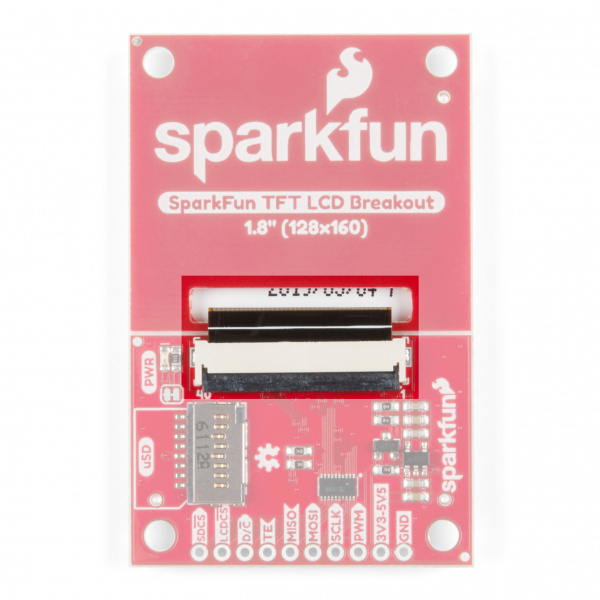
FPC Connector
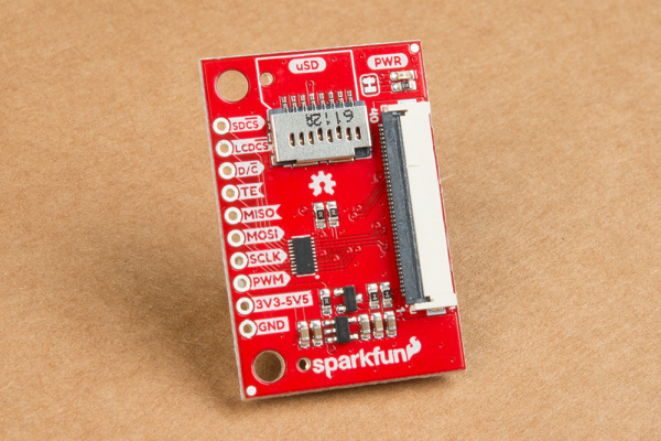
The FPC connector is convenient for two reasons. First, it's extremely simple to (re)connect the display to the breakout board. Second, production of this product is made easier because all soldering can be done in our normal surface mount process.
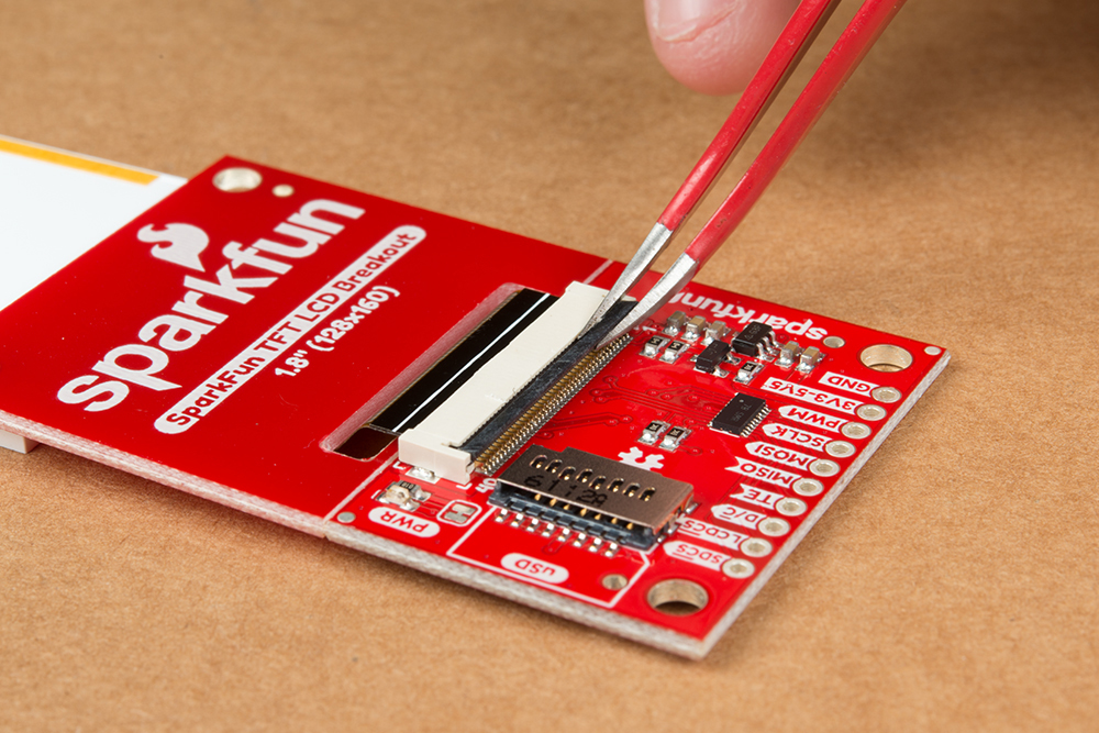
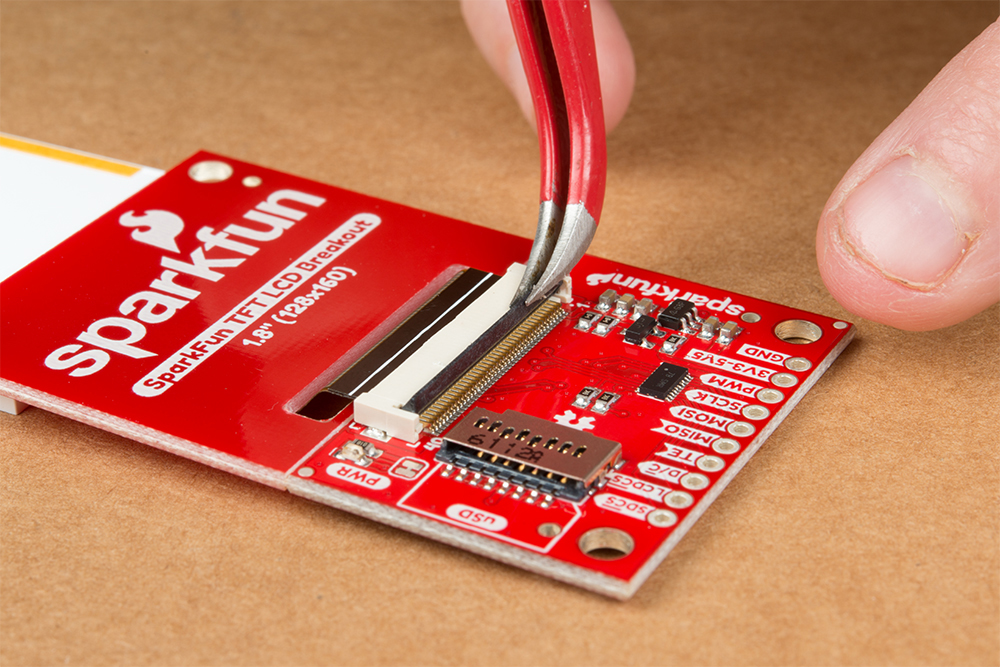
To disconnect the TFT module just flip up the black locking bar with a finger or pair of tweezers and then gently pull the cable straight out from the connector. To put the cable back in, first make sure that the polarity indicators on the cable (1, 40) match up with those on the board and that the black locking bar is flipped up. Next push the cable in evenly for about 2mm.
Click on any of the below images for a closer look at what's going on:
 |
 |
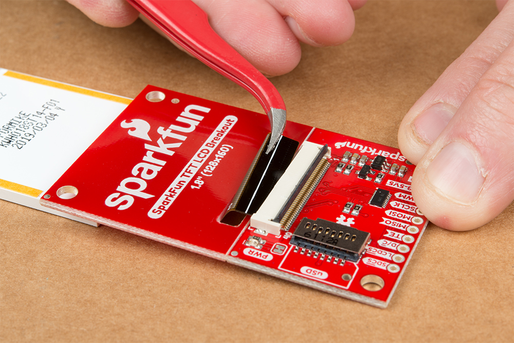 |
| Grasp Black Locking Bar | Lift Black Locking Bar Up | Gently Pull TFT Connector Out |
microSD Card Holder
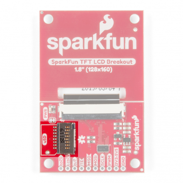
The microSD card holder is there to relieve your microcontroller's poor memory due to having to store hundreds of images of cats, or really whatever you want to keep there. The SD card is connected to the same SPI bus as the display, which in turn keeps the required pin count low.
Breakaway Panel
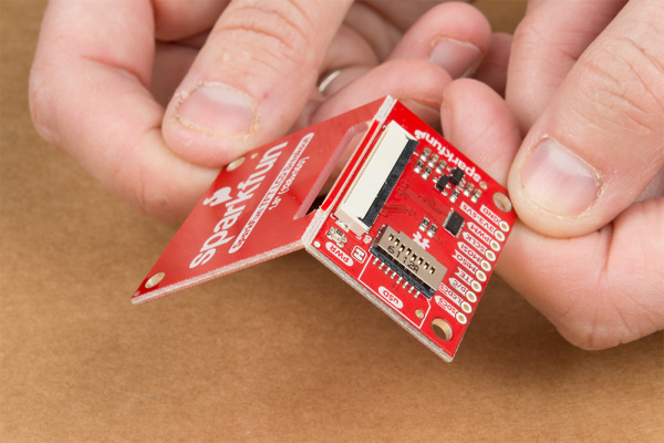
Out of the box, the TFT will come with a large backing PCB that makes it easy to securely mount the display in a project. If you need a more flexible solution you can remove the display module, snap off half the backing board, and then re-insert the display module. When this is done you'll be left with the bare minimum frame around the display to more seamlessly integrate with your project.
Pinout
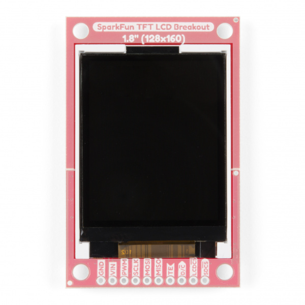
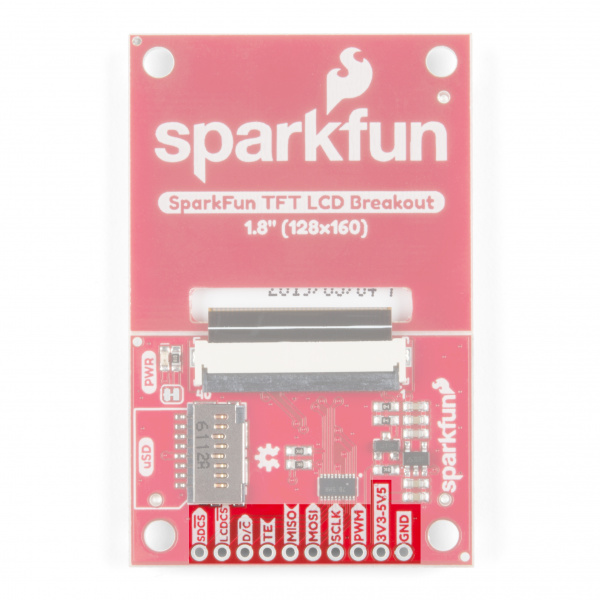
The pinout of this breakout includes the standard SPI interfaces for both the TFT and the microSD card as well as a few specialty pins. You can power the breakout with either 5V or 3.3V thanks to the onboard voltage regulator and level shifter.
- SDCS : The microSD card chip select, pull this pin low to talk to the microSD card
- LCDCS : Chip select for the display, pull it low to talk to the TFT module
- D/C : This is a special signal found in many display controllers. When it is high the incoming data is interpreted as data as opposed to commands when it is low.
- TE : Tearing Effect is an optional output from the display to synchronize data writes - to avoid the 'Tearing Effect' that is seen when data is changed halfway through a screen refresh
- MISO : On this line the microSD card sends data back to the uC
- MOSI : The uC uses this line to send data into the TFT or microSD
- SCLK : Provides synchronization, but rates of up to 32 MHz are possible
- PWM : MOSFET input that allows a PWM signal to dim the backlight
- 3V3-5V5 : Since the breakout has a voltage regulator and level shifter built in you can use it with either of these two popular voltages.
- GND : It is important to stay grounded!
Board Dimensions
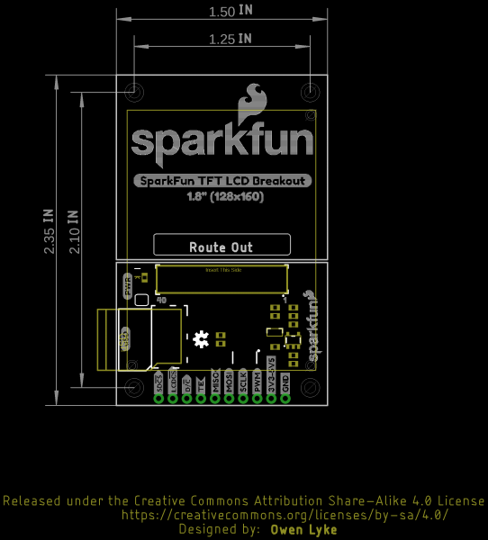
The board is 2.35" x 1.50" and includes four mounting holes for 4-40 standoffs by each corner of the board.
Hardware Hookup
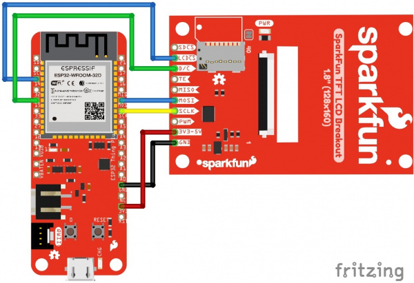
So you've got this breakout board with a whole bunch of pins and all you want to do is make sure it works before you write a bunch of code, right? Let's talk about the bare minimum connections required to get things working.
| Required for TFT Display | |||
|---|---|---|---|
| Breakout Pin | Arduino Uno | Esp32 Thing Plus | Microcontroller Pin Requirements |
| MOSI | 11 | 18/MOSI | Data output of chosen SPI port |
| SCLK | 13 | 5/SCK | Clock output of chosen SPI port |
| LCDCS | 5 | 14 | An output pin |
| D/C | 6 | 15 | An output pin |
| Required for microSD Card | |||
|---|---|---|---|
| Breakout Pin | Arduino Uno | Esp32 Thing Plus | Microcontroller Pin Requirements |
| MOSI | 11 | 18/MOSI | Data output of chosen SPI port |
| MISO | 12 | 19/MISO | Data input of chosen SPI port |
| SCLK | 13 | 5/SCK | Clock output of chosen SPI port |
| SDCS | 4 | 27 | An output pin |
| Completely Optional | |||
|---|---|---|---|
| Breakout Pin | Arduino Uno | Esp32 Thing Plus | Microcontroller Pin Requirements |
| PWM | 3 | 21 | An output pin, ideally PWM capable |
| TE | 7 | 17 | An input pin, ideally interrupt capable |
Software Setup
Since the driver IC conveniently supports the SPI protocol you could start using it with just the stock Arduino libraries - but nobody wants to recreate the proverbial 'wheel' of computer graphics so we will get tricked out with the SparkFun HyperDisplay library and a driver made especially for this breakout.
Everything You Should Know About HyperDisplay
HyperDisplay is an abstracted library for pretty much any 2D graphics display and has a focus on extensibility. Since the interface is standardized you can write display applications just once and make them work on many different displays with a few small changes. If you want to go more in depth check out this HyperDisplay tutorial. To get your TFT breakout working as soon as possible just keep reading along!
To use the breakout with HyperDisplay you will need to have all three of the following libraries installed in your Arduino IDE. You can head on over to the individual GitHub pages to download or simply click the appropriate link for each of the libraries listed below:
| Library Name | Arduino Library Manager Search Term | GitHub Link | Download Link |
|---|---|---|---|
| HyperDisplay | SparkFun HyperDisplay | HyperDisplay GitHub | HyperDisplay Download |
| HyperDisplay ILI9163C | SparkFun HyperDisplay ILI9163C | ILI9163C GitHub | ILI9163C Download |
| HyperDisplay KWH018ST01 4WSPI | SparkFun HyperDisplay KWH018ST01 4WSPI | KWH018ST01 4WSPI GitHub | KWH018ST01 4WSPI Download |
Check out this tutorial on how to install an Arduino library if you are unfamiliar.
Each of the libraries above contain some examples, however the ones that will actually make your TFT breakout light up are contained in the 'KWH018ST01' library -- in case you are wondering that name comes from the name of the TFT module that is used on the breakout. Once your libraries have been installed move on to the next section and try out a few of the examples.
Example Sketches
The HyperDisplay library for the TFT breakout is named after the LCD module that it uses - the KWH018ST01. If you've properly installed the required libraries, you'll notice a number of examples in File -> Examples -> SparkFun HyperDisplay KWH018ST01 4WSPI.
All of the following examples are explained in depth in the Everything You Should Know About HyperDisplay Tutorial. We'll show you a quick overview of each example here, but if you want more information on how these examples and their code work, head on over to the HyperDisplay Tutorial.
Everything You Should Know About HyperDisplay
Examples 1-3
These are basic sketches to help you get the TFT running and show you the options for working with HyperDisplay.
Example 1
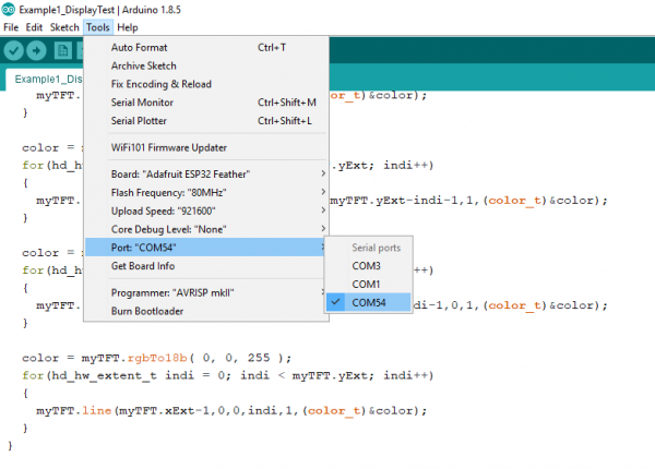
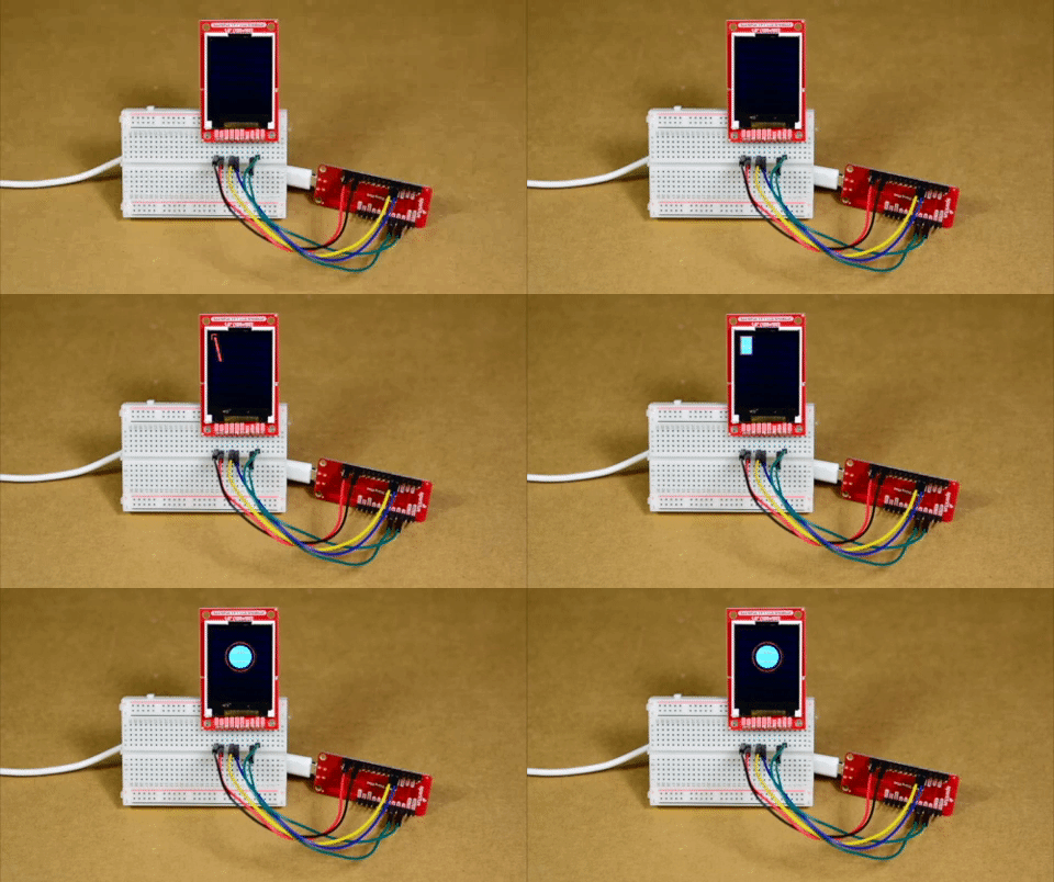
This first example just helps you determine if everything is hooked up correctly and you can upload code and images to your modules. To start, go to File->Examples->SparkFun HyperDisplay KWH018ST01 4WSPI Library and load Example1_DisplayTest. Make sure you have the correct board selected, as well as the correct COM port. In windows, it will look like this:
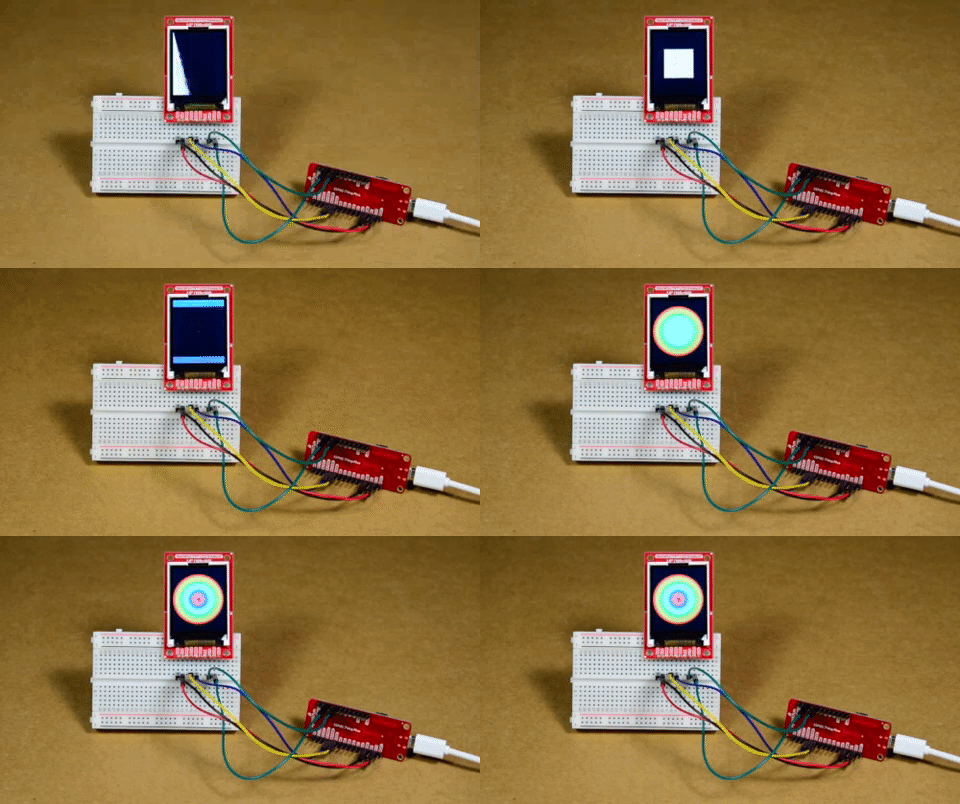
Upload your code, and you should see the following:
Does it work? If not, go back to the Hardware Hookup section and make sure all the connections are set correctly.
Example 2
This code walks you through the simplest uses of HyperDisplay so that you can start to write your own code. To start, go to File->Examples->SparkFun HyperDisplay KWH018ST01 4WSPI Library and load Example2_HyperDisplayBasics. As above, please make sure you have the correct board selected, as well as the correct COM port. Go ahead and upload your code.
Example 3
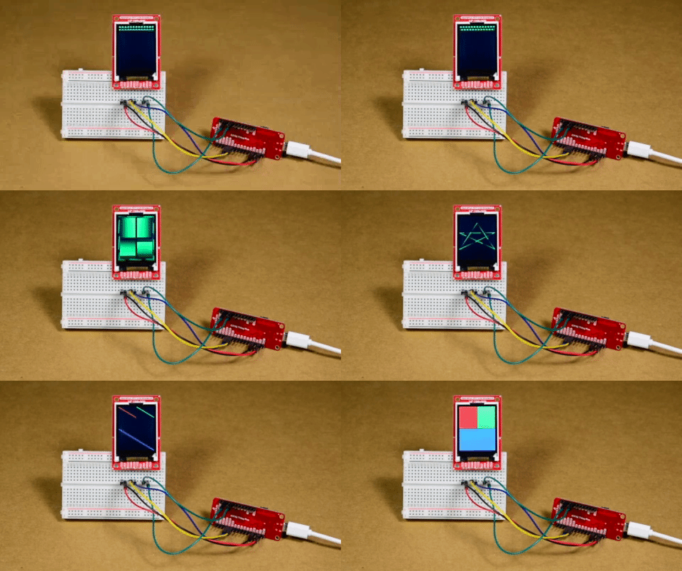
Example 3 goes over all the options currently available in the HyperDisplay drawing functions. To start, go to File->Examples->SparkFun HyperDisplay KWH018ST01 4WSPI Library and load Example3_AdvancedHyperDisplay. As above, please make sure you have the correct board selected, as well as the correct COM port. Go ahead and upload your code.
If everything is set up correctly, you should see the following. As noted above, text capabilities for the ESP32 Thing Plus are still a work in progress. Arduino boards will show some text, ESP32 Thing Plus boards will not.
Examples 4-6
These examples require a microcontroller with at least 6 kB RAM such as the Esp32 Thing Plus.
Example 4
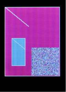
This example shows you the basics of how to use the buffering abilities of HyperDisplay. To start, go to File->Examples->SparkFun HyperDisplay KWH018ST01 4WSPI Library and load Example4_BufferingHyperDisplay. As above, please make sure you have the correct board selected, as well as the correct COM port. Go ahead and upload your code.
You should see something like what we have pictured here:
What you see may not be exactly what we have pictured here - some boards (like the ESP32 Thing Plus) have advanced memory protections in place and will not access uninitialized memory.
Example 5
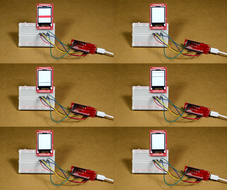
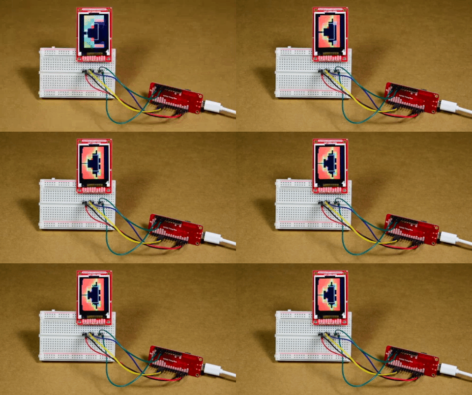
This example highlights a unique use of a TFT display - visualizing the contents of RAM. Open Example5_ExploringRAM from the File->Examples->SparkFun HyperDisplay KWH018ST01 4WSPI Library folder and upload your code. You'll see something like the following:
Example 9
Example9_Fractals uses Nick Gammon's Big Number Library to explore the Mandelbrot set fractal. It takes a few minutes to run through all the calculations, but the result is this beautiful image below:
If you've followed along with the examples then you're well enough acquainted with the capabilities of your TFT breakout and the HyperDisplay library to venture out and start writing your own code. Fly, be free, and make something neat!
Resources and Going Further
For more information, check out some of the resources listed here:
- Schematic (PDF)
- Eagle Files (ZIP)
- Board Dimensions (PNG)
- Datasheets
- HyperDisplay Tutorial Link
- Arduino Libraries
- LCD TFT Breakout GitHub Repo
- SFE Product Showcase
Need inspiration? Check out these other great display tutorials from SparkFun:
