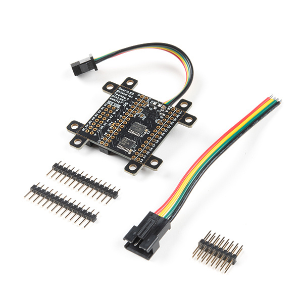
Getting Started with the SmartLED Shield for Teensy
 bboyho
 Introduction
The PixelMatix SmartLED shield for Teensy makes it easy to connect to RGB LED matrix panels! The shield makes it easy to connect to the 16 pins required to drive the display, connects an external 5V supply to power the display and Teensy, and brings out the Teensy’s free signals to a convenient header.
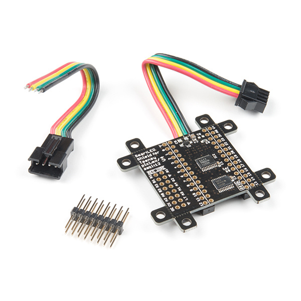
SmartLED Shield V4 for Teensy 3
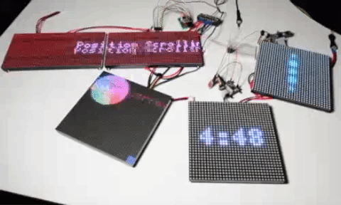
DEV-15046In this tutorial, we will explore a some of the examples provided with the SmartLED shield using different RGB LED matrix panel sizes.
Required Materials
To follow along with this tutorial, you will need the following materials. You may not need everything though depending on what you have. Add it to your cart, read through the guide, and adjust the cart as necessary.
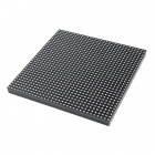
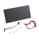
RGB LED Matrix Panel
You will need a panel. The following has been tested to work with the examples provided.
RGB LED Matrix Panel - 32x64
COM-14718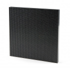
RGB LED Matrix Panel - 64x64
COM-14824- 1:16 with 32 rows
- 1:8 with 16 rows
- 1:32 with 64 rows
For example, if you are trying to use a 32x32 panel with a 1:8 scan rate, it may not display as expected.
Teensy
To control the panel using the SmartLED shield, you will need a Teensy. You can use a Teensy 4.0 but you would need to make sure that you are using the appropriate SmartLED Shield version or adapter.
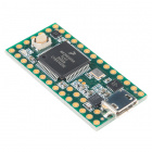
Teensy 3.2
DEV-13736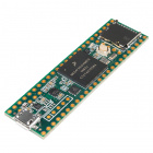
Teensy 3.5
DEV-14055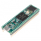
Teensy 3.5 (Headers)
DEV-14056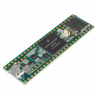
Teensy 3.6
DEV-14057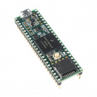
Teensy 3.6 (Headers)
DEV-14058Power
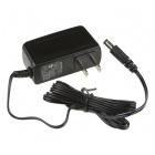
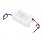
You will also need a 5V power supply. A 5V wall adapter and barrel jack adapter is the easiest way to connect power to the panel and Teensy. However, there are other methods depending on how you are powering the panel.
Additional Components
Depending on your setup and how you are controlling the panel, you may need these additional components.


microSD USB Reader
COM-13004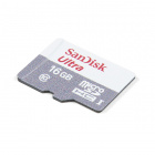
microSD Card - 16GB (Class 10)
COM-15051Tools
Depending on your setup, you may need pliers, a soldering iron, solder, and general soldering accessories.


Weller WLC100 Soldering Station
TOL-14228Suggested Reading
If you aren’t familiar with the following concepts, we recommend checking out these tutorials before continuing.
How to Power a Project
What is an Arduino?
RGB Panel Hookup Guide
Getting Started with the Teensy
Hardware Overview
Teensy Footprint
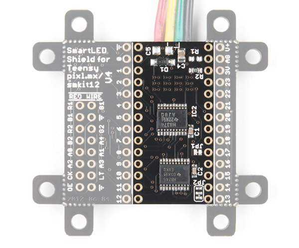
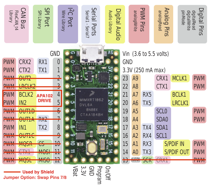
The SmartLED shield makes it easy to connect to RGB LED matrix panels. As opposed to wiring to 16 pins on the RGB LED matrix panel, you simply sandwich the shield between a Teensy and the IDC connector! The top of the board is where you would insert the Teensy populated with straight headers. The bottom of the shield includes female headers to make a secure connection.
 |
 |
| Teensy Footprint (Top View) | Teensy Footprint (Bottom View) |
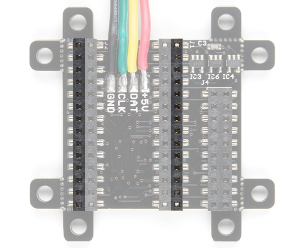
Adjacent to the Teensy footprint are additional pins that are broken out for easy access for prototyping or soldering wires directly to the shield.
 |
 |
| Teensy Pins Broken Out (Top View) | Teensy Pins Broken Out (Bottom View) |
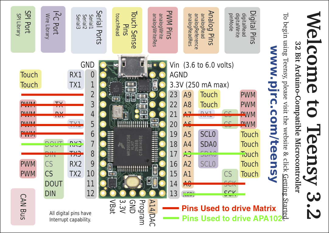
For more information about the reserved pins on the SmartLED matrix shield, check out the image below for the pins that are used to drive the RGB LED matrix panel and APA102 LEDs.

IDC Connector
The shield breaks out the RGB LED matrix panel's IDC pins. Simply align the silkscreen with the panel's input and stack it on like a backpack. As an alternative, you can use an IDC cable and the included 2x8 long, centered header pins. Just make sure to align the cable's red wire with the silkscreen labeled RED WIRE.
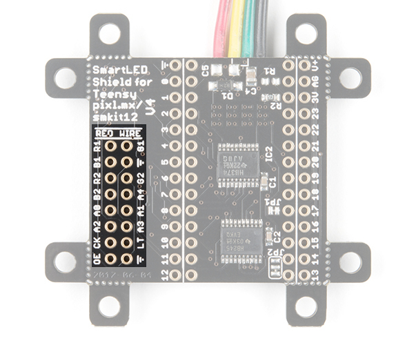 |
 |
| IDC Connector (Top View) | IDC Connector (Bottom View) |
APA102 LED
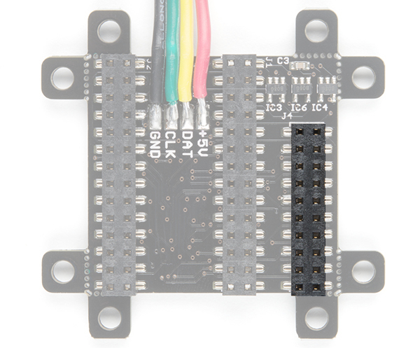
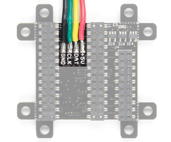
The shield includes additional 4-pin JST SM connector pair to connect a strip or matrix of APA102 LEDs from the SmartLED Shield.
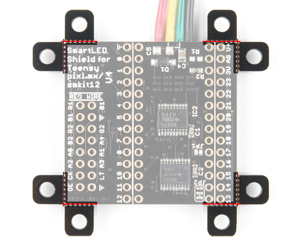
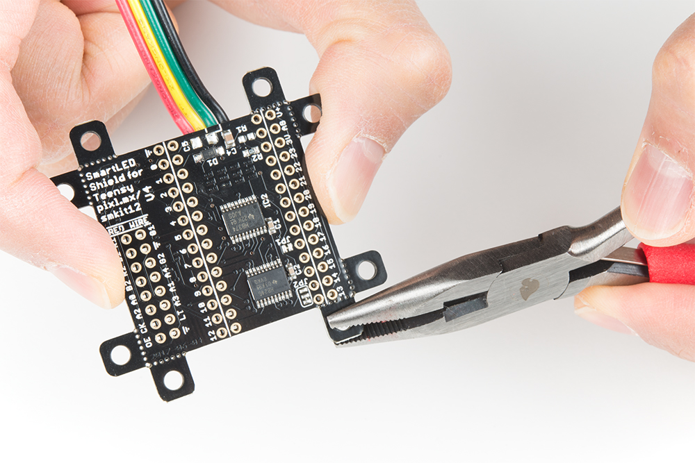
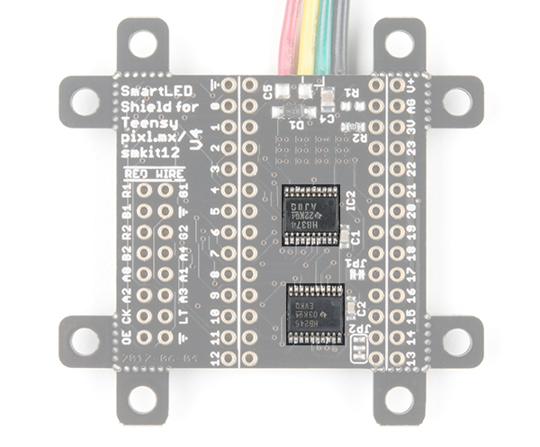
Removable Mounting Holes
The shield includes mounting holes by each corner of the board. They can be used to to mount the shield when using the IDC cable. They are held to the rest of the board with mouse bites. Each of the mounting holes can be removed using pliers. The image below shows highlights the mounting holes with red lines along the mousebites.
ADDX Pins and Logic Levels
Certain panels may require 5V logic levels, which may not be enough with the Teensy's output pins. While you can try to wire all 16 pins from the Teensy to the IDC cable, it is not the most reliable connection. The panel may flicker or fail to display properly. The SmartLED shield was designed to include level shifting buffers to safely and reliably control the RGB LED matrix panels.
Compatibility with Teensy 4
The pinout of the Teensy 4 are different from the Teensy 3. Make sure that you are using the SmartLED Shield V5 for Teensy 4 or the Teensy 4 adapter with the SmartLED Shield V4.
SmartLED Shield - Teensy 4
DEV-17521Below are reserved pins that are used on the SmartLED Shield V5 for Teensy 4.
Make sure to uncomment the following line by removing the single line comment "//" near the top of the example code.
language:c
//#include <MatrixHardware_Teensy4_ShieldV5.h> // SmartLED Shield for Teensy 4 (V5)
Depending on the hardware that you are using, you may need to adjust the connection and additional lines of code.
Hardware Assembly
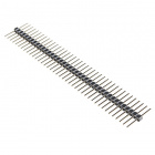
If you have not already, solder the male header pins on your Teensy before connecting. We will be using the 1x14 header pins on each side of a Teensy but you can also solder additional pins or or wires depending on your setup.
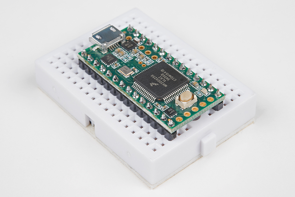
After soldering and removing the flux from a Teensy, stack the Teensy on the SmartLED shield. Make sure to face the USB connector in the same direction as the 4-pin JST SM connector.
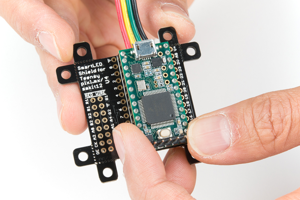
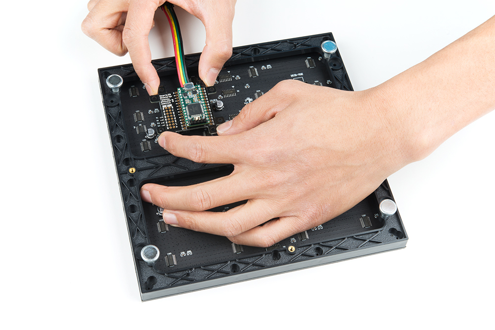
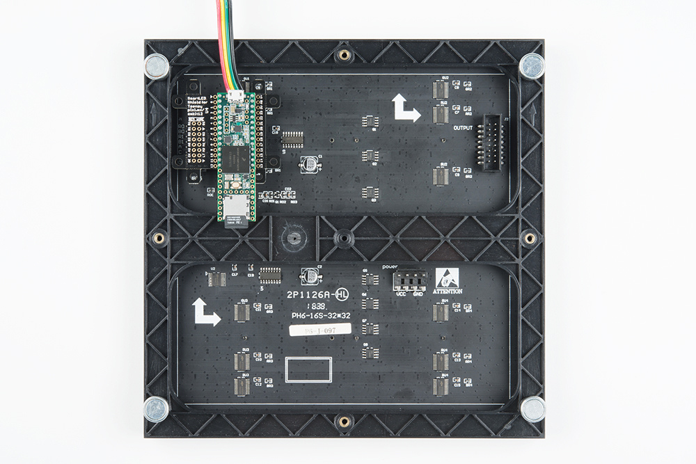
Align the IDC connector breakout on the SmartLED shield with the IDC connector on your RGB LED Matrix Panel. The location of the IDC connector depends on the manufacturer of the panel but usually it will be located on the left side relative to the arrows pointing up and toward the right.
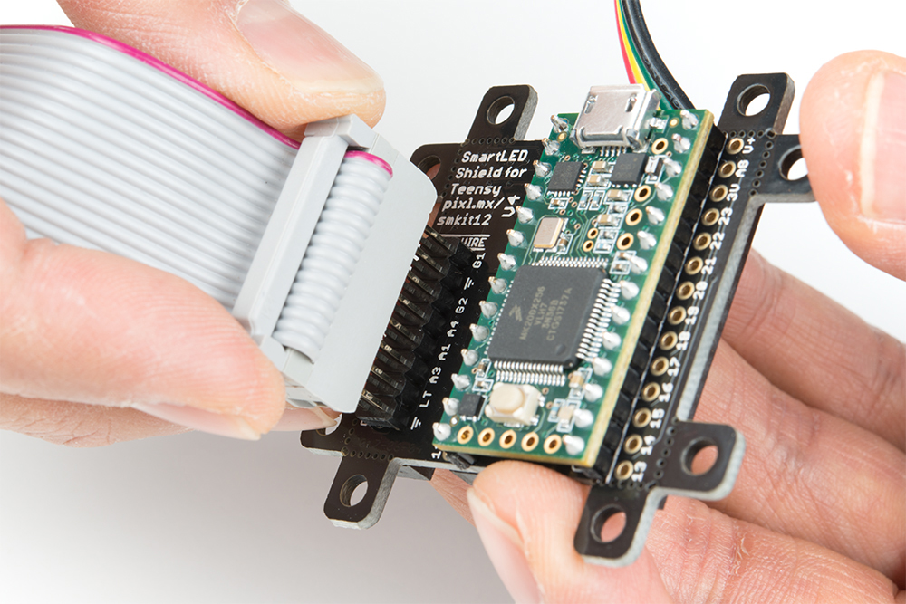
Once connected, the back of your RGB LED matrix panel should look similar to the images below. On the left, a Teensy 3.2 was connected to a 64x64 panel with 3mm pitched LEDs. On the right, a Teensy 3.6 was used for a 32x32 with 6mm pitched LEDs.
 |
 |
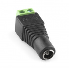
If you have not already, attach a 5V power supply to your RGB LED matrix panel's power cable. If you are using a power supply with a barrel jack, you can use a female barrel jack adapter and screwdriver to get a quick and dirty connection between the spade and barrel jack.
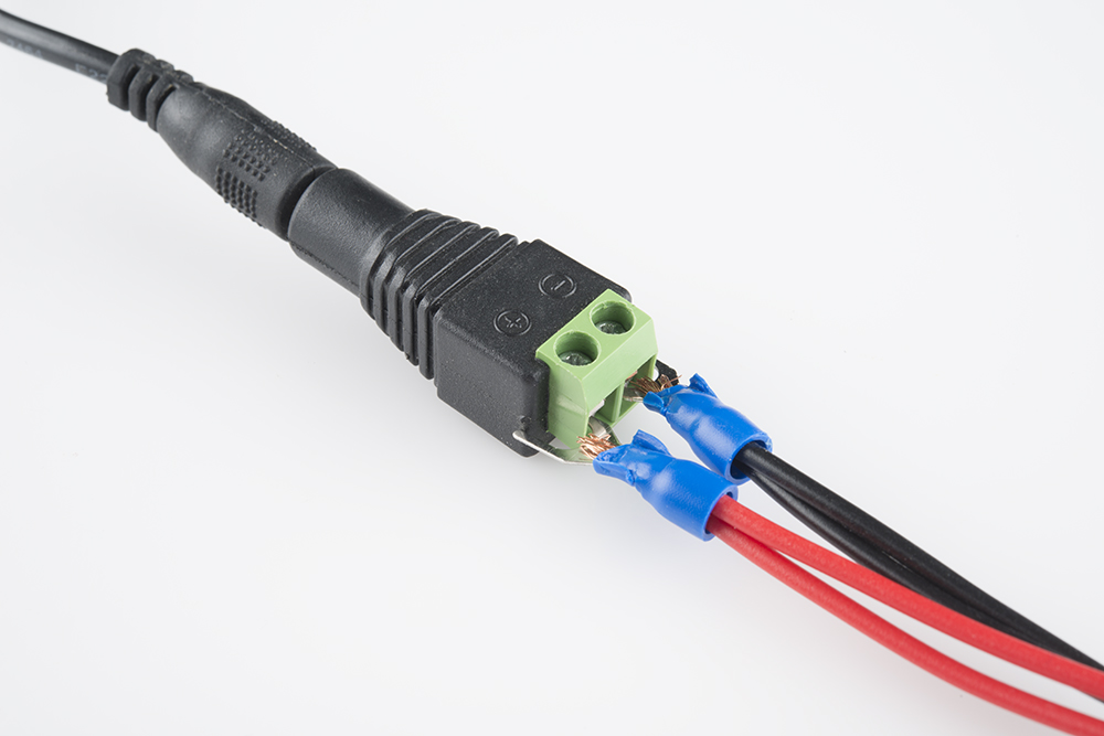
The connection should look similar to the image below. Depending on your 5V power supply, your setup might be slightly different.

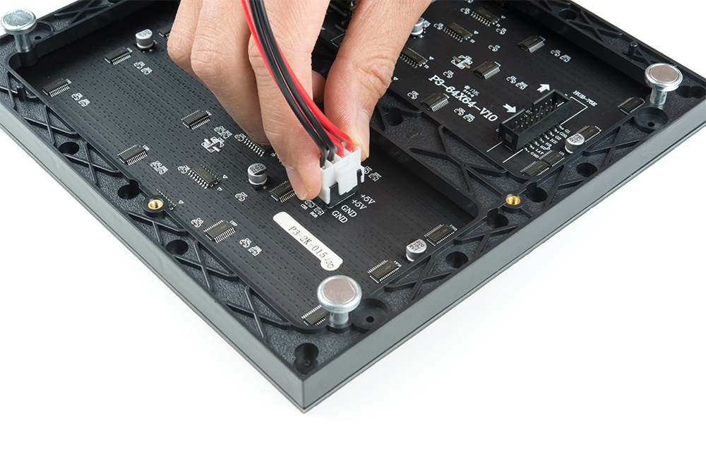
Then slide the polarized power cable for the RGB matrix panel into its respective mating connector. The red wires should be connected to the 5V pins while the black wires connected to the GND pins.
For the scope of this tutorial, we will connect 5V USB power directly to the Teensy's USB connector. This is separate from the power supply that is powering the RGB LED matrix panel. Depending on your setup, you can use the same power supply that the RGB LED matrix panel is using by connecting to either the Teensy's V+ and GND pins or the APA102 JST SM connector. Just make sure that the voltage is regulated at 5V.
Alternative Connections
There is an option to daisy chain the panels together if you are within the limits of the SmartLED library. Simply connect the output from the first panel to the input of the second panel. Make sure to provide power to each panel through the 4-pin polarized connector.
As explained earlier, you can try to wire all 16 pins from the Teensy to the panel's IDC cable. It is not the most reliable connection. There is a higher probability of wiring incorrectly or a connection becoming loose. For more information on trying the connection, check out the table below. This connection is not possible when wiring to a 64x64 panel due to the extra 5th addressing pin.
| Panel Pin Label | Cable Connector Pin # | Teensy 3 | Notes |
|---|---|---|---|
| R0 | 1 | 2 | Red Data (columns 1-16) |
| G0 | 2 | 5 | Green Data (columns 1-16) |
| B0 | 3 | 6 | Blue Data (columns 1-16) |
| GND | 4 | GND | Ground |
| R1 | 5 | 21 | Red Data (columns 17-32) |
| G1 | 6 | 8 | Green Data (columns 17-32) |
| B1 | 7 | 20 | Blue Data (columns 17-32) |
| GND | 8 | GND | Ground |
| A | 9 | 15 | Demux Input A0 |
| B | 10 | 22 | Demux Input A1 |
| C | 11 | 23 | Demux Input A2 |
| D | 12 | 9 | Demux Input E1, E3 (32x32 panels only) |
| CLK | 13 | 14 | LED Drivers' Clock |
| STB | 14 | 3, 8 | LED Drivers' Latch |
| OE | 15 | 4 | LED Drivers' Output Enable |
| GND | 16 | GND | Ground |
Software Installation
Note: This example assumes you are using the latest version of the Arduino IDE on your desktop. If this is your first time using Arduino, please review our tutorial on installing the Arduino IDE. If you have not previously installed an Arduino library, please check out our installation guide.
Teensyduino Add-On
If you haven't used Teensy before, you'll need to download and install the extension for the Arduino IDE called Teensyduino from PJRC. This will also install the drivers for the board. Follow the instructions on installing the add-on before continuing on.
Install Library
Louis Beaudoin has written an amazing library to control the RGB LED matrix panels. You can obtain these libraries through the Arduino Library Manager. Search for SmartMatrix and you should be able to install the latest version. If you prefer downloading the libraries manually you can also grab them from the GitHub repository:
Library Overview
For an overview of the functions, check out documentation in the MIGRATION.md file from the GitHub repository.
Example: Feature Demo!
There are a few examples from the SmartMatrix library for the SmartLED Shield. For the scope of the tutorial, we will be highlighting three of the examples.
Feature Demo!
Let's start with the feature demo. After installing the library, click File > Examples > SmartMatrix > FeatureDemo.ino in the Arduino IDE. Once open, there are a minimum of 4 lines to modify to get the example working with your matrix panel:
- uncomment one line for your MatrixHardware configuration
- e.g. "
#include <MatrixHardware_Teensy3_ShieldV4.h>" if you are using the shield V4 or "#include <MatrixHardware_Teensy4_ShieldV5.h>" if you are using shield V5
- e.g. "
- adjust
kMatrixWidthto the width of your panel - adjust
kMatrixHeightto the height of your panel - adjust
kPanelTypebased on the scan rate of your panel as noted in the MatrixCommonHub75.h header file
- 1:8 scan with 16 rows
- 1:16 scan with 32 rows
- 1:32 scan with 64 rows
For example, if you are trying to use a 32x32 panel with a 1:8 scan rate, it may not display as expected.
64x64 Panel with 1:32 Scan Rate
Let's try modifying the example code to work with the 64x64 panel with a 1:32 scan rate. The SmartLED shield is required to address the extra 5th ADDX pin on the IDC connector.
Parts Needed
To follow this example, you would will need the following materials. You may not need everything though depending on what you have. Add it to your cart, read through the guide, and adjust the cart as necessary.Modifying Code
Adjust the code by simply:
- uncommenting the line for your hardware configuration
- in this case, we chose "
#include <MatrixHardware_Teensy3_ShieldV4.h>" for the Teensy 3 by removing the "//"
- in this case, we chose "
- adjusting kMatrixWidth to the width of your panel by replacing
32with64 - adjusting kMatrixHeight to the height of your panel by replacing
32with64 - adjusting kPanelType by replacing
SMARTMATRIX_HUB75_32ROW_MOD16SCANwithSMARTMATRIX_HUB75_64ROW_MOD32SCANas noted in the MatrixCommonHub75.h header file
Upload Code
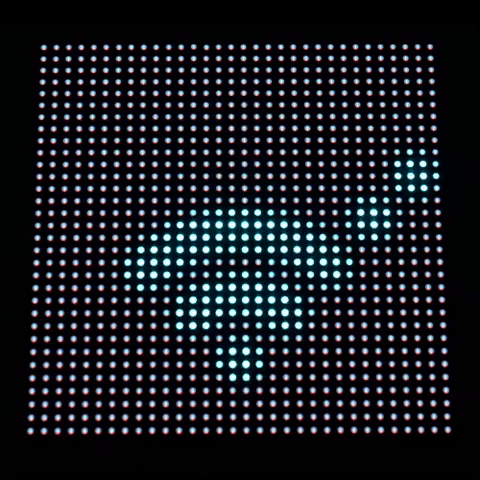
When the changes are completed, select the Teensy board definition with the associated COM port and click upload. You should see the feature demo running. This includes scrolling text, animations, shapes being drawn, brightness changing, and refresh rate changing.
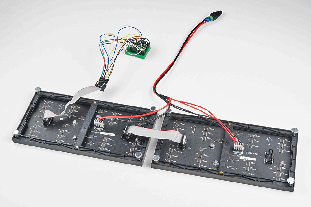
Daisy Chained 32x64 with 1:16 Scan Rate
Let's try modifying the example code to work with two 32x64 panels with a 1:16 scan rate. In this example, we manually wire the connection to a Teensy 3.2.
Parts Needed
To follow this example, you would will need the following materials. You may not need everything though depending on what you have. Add it to your cart, read through the guide, and adjust the cart as necessary.Modifying Code
Modify the original code by:
- leaving the line "
#include <MatrixHardware_Teensy3_ShieldV4.h>" commented out by using the "//" - adjusting kMatrixWidth to the width of your panel by replacing
32with128 - keep kMatrixHeight based on the height of your panel by leaving
32at32 - keep kPanelType by leaving
SMARTMATRIX_HUB75_32ROW_MOD16SCANatSMARTMATRIX_HUB75_32ROW_MOD16SCANas noted in the MatrixCommonHub75.h header file
Upload Code
When the changes are completed, select the Teensy board definition with the associated COM port and click upload. You should see the same demo running but for a matrix size of 32x128!
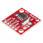
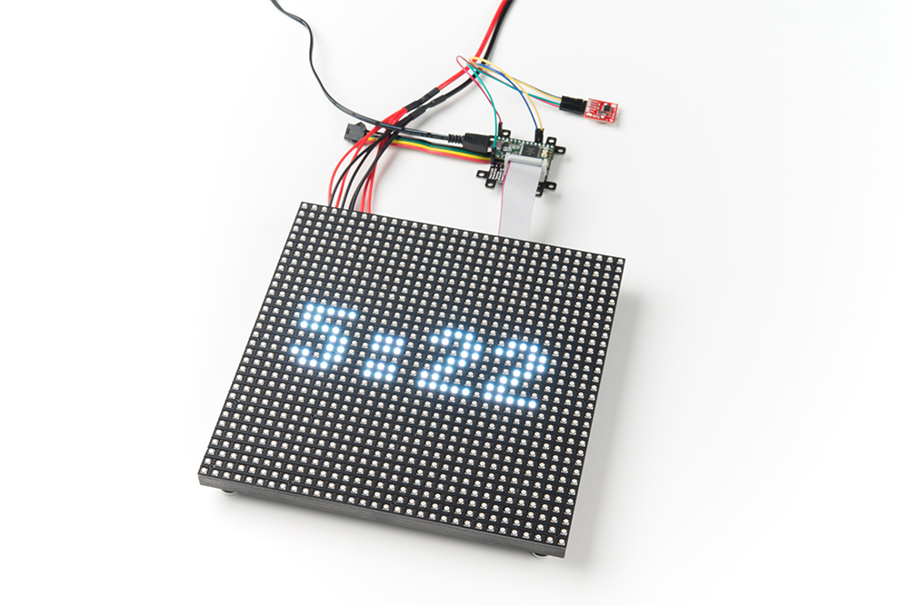
Example: Matrix Clock w/ the DS1307 RTC Module
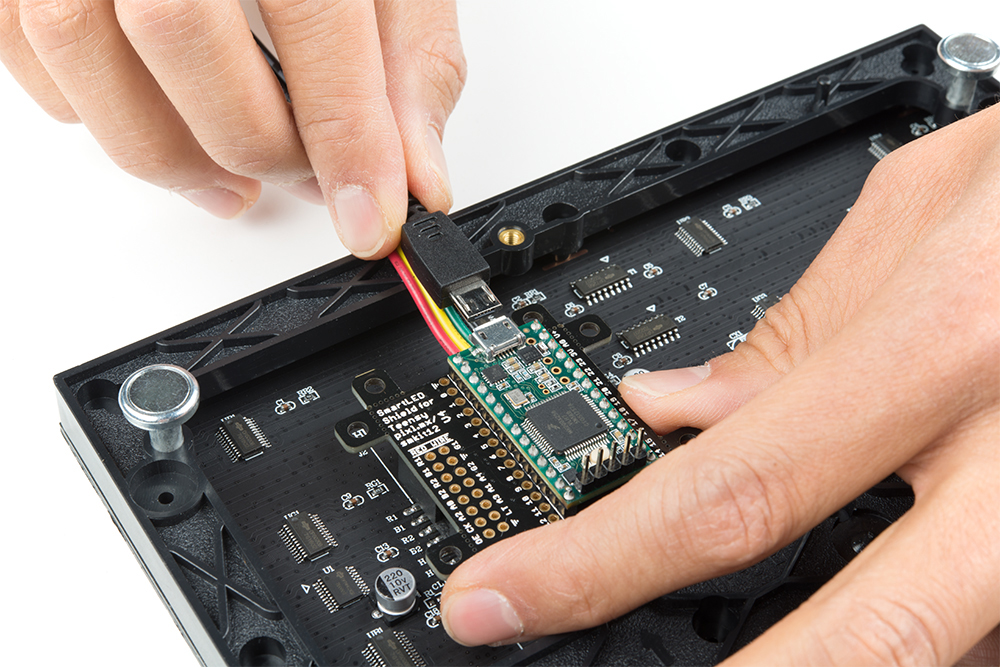
In this example, we will be using the DS1307 RTC module with the SmartLED Shield, Teensy 3.2, and 32x32 panel with 1:16 scan rate. We will use the included 2x8 header and IDC cable instead of mounting the shield on the back of the matrix.
Parts Needed
To follow this example, you would will need the following materials. You may not need everything though depending on what you have. Add it to your cart, read through the guide, and adjust the cart as necessary.Setting Up the DS1307 RTC Module
If you have not already, solder right angle headers to the RTC module.
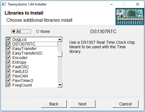
Make sure that you installed PJRC's DS1307RTC and Time libraries with the Teensyduino add-on. You can check by viewing the Arduino program folder where the files were installed under. In this case, it was in the "...Arduino\hardware\teensy\avr\libraries" path.
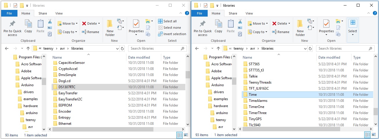
If it is not installed, you can run the Teensyduino add-on installer again to add the associated files. Under Libraries to Install, make sure that the checkbox is checked off for DS1307RTC and Time libraries.
Circuit Diagram 1
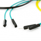
Make the following connection between the DS1307 breakout board and Teensy stacked on the SmartLED shield. If you used right angle headers on the DS1307 breakout board, you can use four M/F jumper wires to connect.
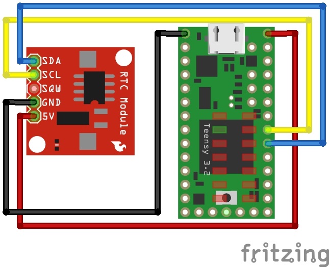
Hookup Table 1
| DS1307 | Teensy |
|---|---|
| SDA | 18 |
| SCL | 19 |
| SQW | N/C |
| GND | GND |
| 5V | V+ |
Upload Code
In the Arduino IDE, open File > Examples > DS1307RTC > SetTime.ino. The sketch will automatically set the date and time for the RTC from the compiler once you upload. You will need to run this code if the battery was removed or the time does not match your time zone. Select the Teensy board definition with the associated COM port and click upload. To check if the clock matches your computer's time, simply open the Arduino serial monitor set at 9600 baud. You should see an output similar to the one shown below.
DS1307 configured Time=13:00:47, Date=Nov 12 2018
DS1307 Communication Error :-{
Please check your circuitry
MatrixClock
Now that the clock is configured, let's output the time to the 32x32 panel!
Circuit Diagram 2
Adjust the SDA and SCL wires as shown in the diagram below.
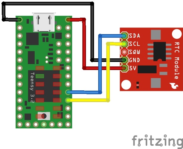
Hookup Table 2
| DS1307 | Teensy |
|---|---|
| SDA | 17 |
| SCL | 16 |
| SQW | N/C |
| GND | GND |
| 5V | V+ |
Notice that the wires are in a different location and flipped? Well that's because the I2C pins are redefined for the SmartMatrix Shield! Make sure to move the pins and switch the order that they are connected.
Modifying Code
Next, open the MatrixClock.ino example by clicking on File > Examples > SmartMatrix > MatrixClock in the Arduino IDE. Since we are using the SmartLED shield and the 32x32 panel with 1:16 scan rate, there is only one line of code that needs to be adjusted. We just need to:
- uncommenting the line for your hardware configuration
- in this case, we chose "
#include <MatrixHardware_Teensy3_ShieldV4.h>" for the Teensy 3 by removing the "//"
- in this case, we chose "
Upload Code
Once the code has been adjusted, select correct board and COM port to upload to the Teensy 3.2. Connect the IDC cable to the SmartLED shield with the 2x8 male header pins. Then add power to the panel and Teensy to view begin viewing the time!
Example: Animated GIFs
In this example, we will take advantage of the built-in microSD card on the Teensy 3.6 to display animated GIFs on a 32x32 panel with 1:16 scan rate.
Parts Needed
To follow this example, you would will need the following materials. You may not need everything though depending on what you have. Add it to your cart, read through the guide, and adjust the cart as necessary.If you haven't already, solder the headers on the Teensy 3.6. Then insert the development board into the SmartLED shield's socket.
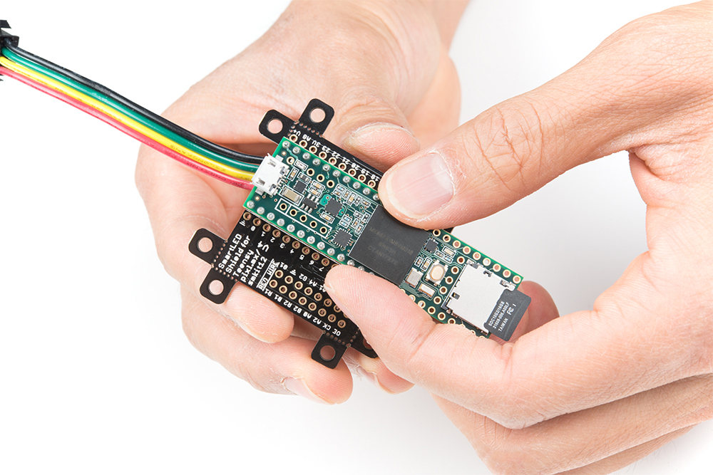
Right angle headers would be better for a low profile behind the RGB LED matrix panel. You can also solder wire to the connections depending on your setup.
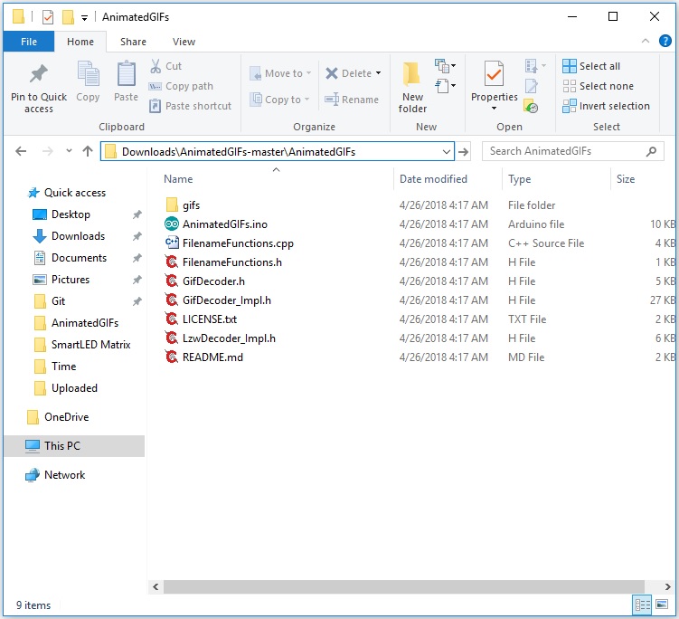
You may notice that there is a GitHub subtree called "AnimatedGIFs @ ..." that was pulled into the SmartMatrix library's examples folder. However, the folder may not have been included when installing the library via the Arduino Library Manager. If you do not see the folder from the Arduino IDE under File > Examples > SmartMatrix > Animated GIFs, you will need to download and unzip the files from this repository:
Once the folder is unzipped, make sure that the AnimatedGIFs.ino file and all associated files are under the same folder name called ".../AnimatedGIFs" as shown in the image below.
Modifying Code
Open the AnimatedGIFs.ino example. Since the defaults kMatrixWidth, kMatrixHeight, and kPanelType are already set for the 32x32 panel with 1:16 scan rate, we just need to:
- uncommenting the line for your hardware configuration
- in this case, we chose "
#include <MatrixHardware_Teensy3_ShieldV4.h>" for the Teensy 3 by removing the "//"
- in this case, we chose "
- uncomment line "
//#define SD_CS BUILTIN_SDCARD" by removing the "//" - comment next line "
#define SD_CS 15" by adding the "//"
Upload Code
Once the code has been adjusted, select correct board and COM port to upload to the Teensy 3.6.
Adding GIFs
The next step is to add the .../gifs folder into the microSD card. Remove power from the Teensy 3.6 if a microSD card was inserted in the socket. Connect to the memory card using a card adapter or microSD USB reader. Copy and paste the .../gifs folder into the root directory of the memory card.
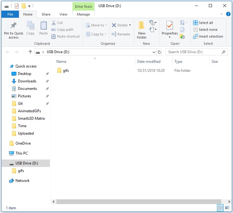
Safely remove the memory card from your computer by ejecting or unmounting the microSD card. After removing the memory card from the adapter or USB reader, insert it into the built-in microSD card socket on the Teensy.
Stack the board on the panel's IDC connector.
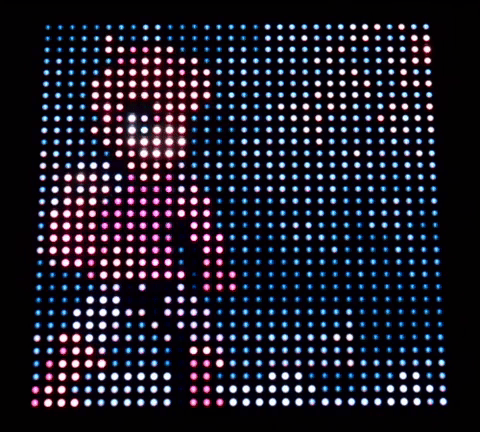
If you have not already, add power to the panel. Then add power to the Teensy. The Teensy will begin displaying the GIFs that were included in the folder. Pretty neat!
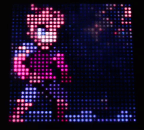
Diffusing the LEDs
The animations may be hard to view as you can see on the image on the left. To help diffuse the light, a translucent material placed in the front of the panel to blend the pixels. The image on the right used a piece of white paper to blend the individual pixels. For long term installations, try using frosted acrylic as used in the Aurora project.
 |
 |
| Without Diffusion | Diffused Panel |
Adding MOAR GIFs
Looking for more GIFs? Try checking the GIFs provided in the Aurora project:
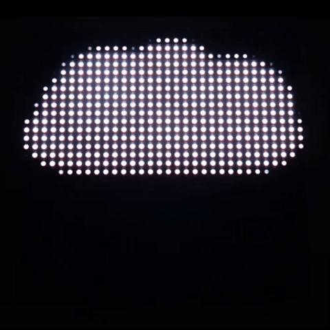
Simply copy any file with the *.gif extension and include it in the .../gifs folder as explained earlier. The 10x weather GIFs are neat animations if you want display the current weather on a panel for your next cloud connected IoT project!
You can also do a custom search for 32x32 GIFs on Google.
Resources and Going Further
Now that you've successfully got your SmartLED shield for Teensy up and running, it's time to incorporate it into your own project!
For more information, check out the resources below:
Need some inspiration for your next project? Check out some of these related tutorials using a Raspberry Pi or an ESP32 to control the panels! Keep in mind the boards require a different library to control the RGB LED Matrix Panel.
RGB Panel Jumbotron
Maybe try making a hover pong game with the 32x32 RGB LED Matrix using a gesture sensor and the SmartLED Shield. The example code can be found in the GitHub repo HoverPong.
Or check out the old Aurora project. The project combines clock and animated GIFs examples with an IR remote and receiver for a dynamic display. The code also includes the ability to react to sound using a MSGEQ7