SparkPunk Sequencer Hookup Guide
 Byron J.
Introduction
In this tutorial, we will assemble and use the SparkPunk Sequencer kit.
SparkFun SparkPunk Sequencer Kit
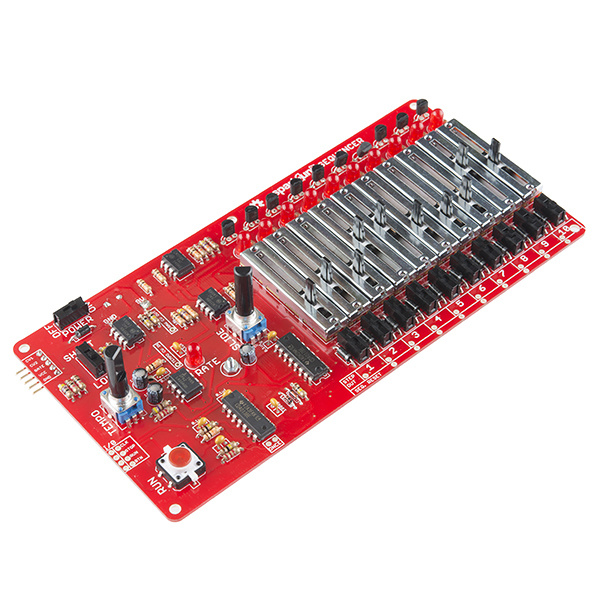
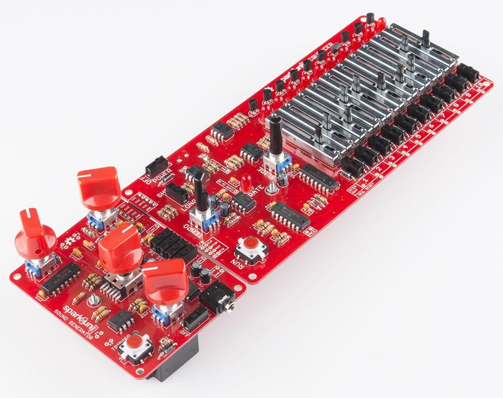
KIT-12707The SparkPunk Sequencer kit is an analog control voltage sequencer designed to drive the SparkPunk Sound Generator.
An Abbreviated History Of Sequencers
In general, a sequencer is a device that produces timed control signals in a particular order. These signals are used for many purposes - for instance, the electronic module that operates a set of traffic signals is one type sequencer, the control system that runs an elevator is another. Both have to produce the correct signals, in the proper order, with the right timing (such as stopping east-west traffic when north-south traffic is moving, then making sure the yellow light is illuminated for the correct period when the light changes).
Musical sequencers are used to control musical instruments. They generate signals to control performance parameters such as pitch and timbre, with specific rhythmic timing. The original sequencers, such as Raymond Scott's circle machine, were capable of generating short, repeating musical phrases. More recently, sequencers have evolved into large software packages running on computers, generating MIDI and audio events, capable of creating complete musical compositions.
The SparkPunk Sequencer is reminiscent of its analog forebears. It cycles among ten steps, reading the slider and switch for each, producing corresponding analog voltages on the output pins. It offers hands-on control, with its array of knobs, sliders, and switches. It seamlessly integrates with the SparkPunk Sound Generator for your creative musical enjoyment.
This tutorial will guide you through the assembly and testing of the SparkPunk Sequencer.
Before We Begin
The SparkPunk Sequencer is more complex than most SparkFun soldering kits. It has a greater variety of components, mounted on a larger board. If you're new to soldering kits, or need some practice with component identification, we can recommend a number of simpler kits to help you get up to speed.
The sequencer is intended to control the SparkPunk Sound Generator. If you have purchased both kits together, we recommend that you start by assembling and testing the sound generator, then build the sequencer. In later steps, we'll be using the sound generator to test the sequencer, and that process will be smoother if you're confident that the sound generator is functional.
SparkPunk Hookup Guide
Necessary Tools
- Soldering Iron
- Lead-based or Lead-free solder
- Diagonal or Flush cutters
- Small Philips Screwdriver
Additional Tools and Supplies
- Safety Glasses
- Magnifying glass or Loupe
- PCB Vise or Third Hand
- Volt Meter
- Removable tape, such as painter's or gaffer's tape
Suggested Reading
Kit Contents
Let's begin by taking inventory of the parts in the kit. You can organize parts in the groupings shown below, which will make them easier to locate as you assemble the kit.
Circuit Board
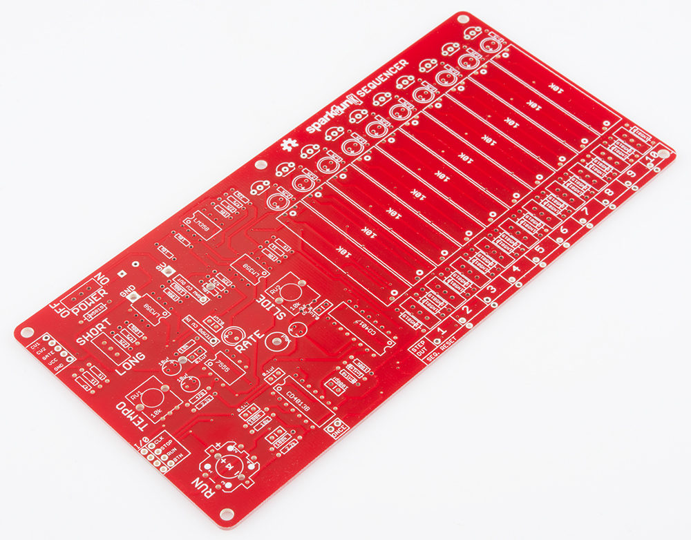
- One SparkPunk Sequencer PCB
Diodes
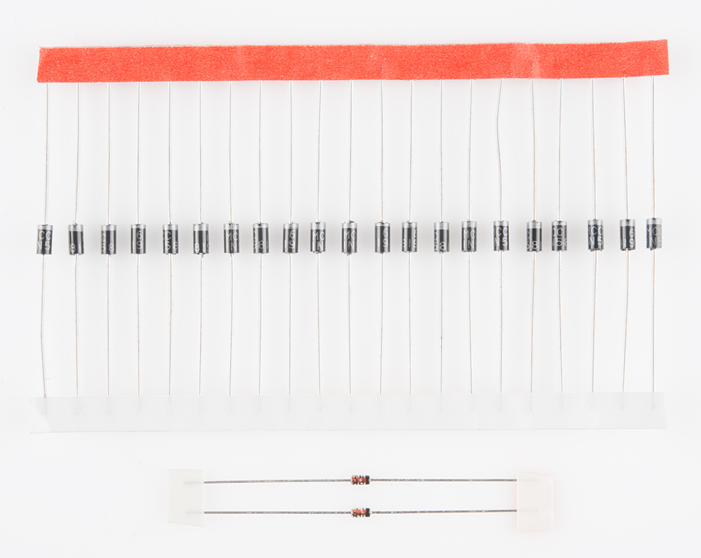
- Twenty-one 1N5819 Schottky diodes
- Two 1N4148 Silicon diodes
Resistors

- Six 100k Ohm 1/4W Resistors (Brown - Black - Yellow - Gold)
- Three 47K Ohm 1/4W Resistors (Yellow - Violet - Orange - Gold)
- Four 1K Ohm 1/4W Resistors (Brown - Black - Red - Gold)
- One 33K Ohm 1/4W Resistor (Orange - Orange - Orange - Gold)
- One 470 Ohm 1/4W Resistor (Yellow - Violet - Brown - Gold)
- One 47 Ohm 1/4W Resistor (Yellow - Violet - Black - Gold)
- Twelve 2.2K Ohm 1/4W Resistors (Red - Red - Red - Gold)
- Seven 10k Ohm 1/4W Resistors (Brown - Black - Orange - Gold)
- Three 22K Ohm 1/4W Resistors (Red - Red - Orange - Gold)
Capacitors

You may need a magnifying glass to read the markings on the ceramic capacitors.
- One 1000uF 25V Electrolytic Capacitor
- Three 10uF 25V Electrolytic Capacitor
- Six 0.1uF Ceramic Capacitor (marked 104)
- One 1nF Ceramic Capacitor (marked 102)
Integrated Circuits
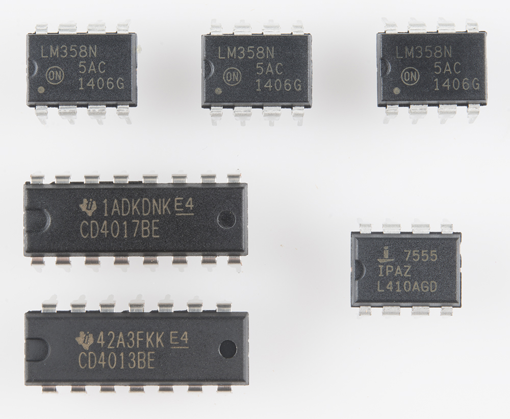
- Three LM358N dual operational amplifiers
- One CD4017BE one-of-ten counter/demultiplexer
- One CD4013BE dual flip-flop
- One ICM 7555
Semiconductors
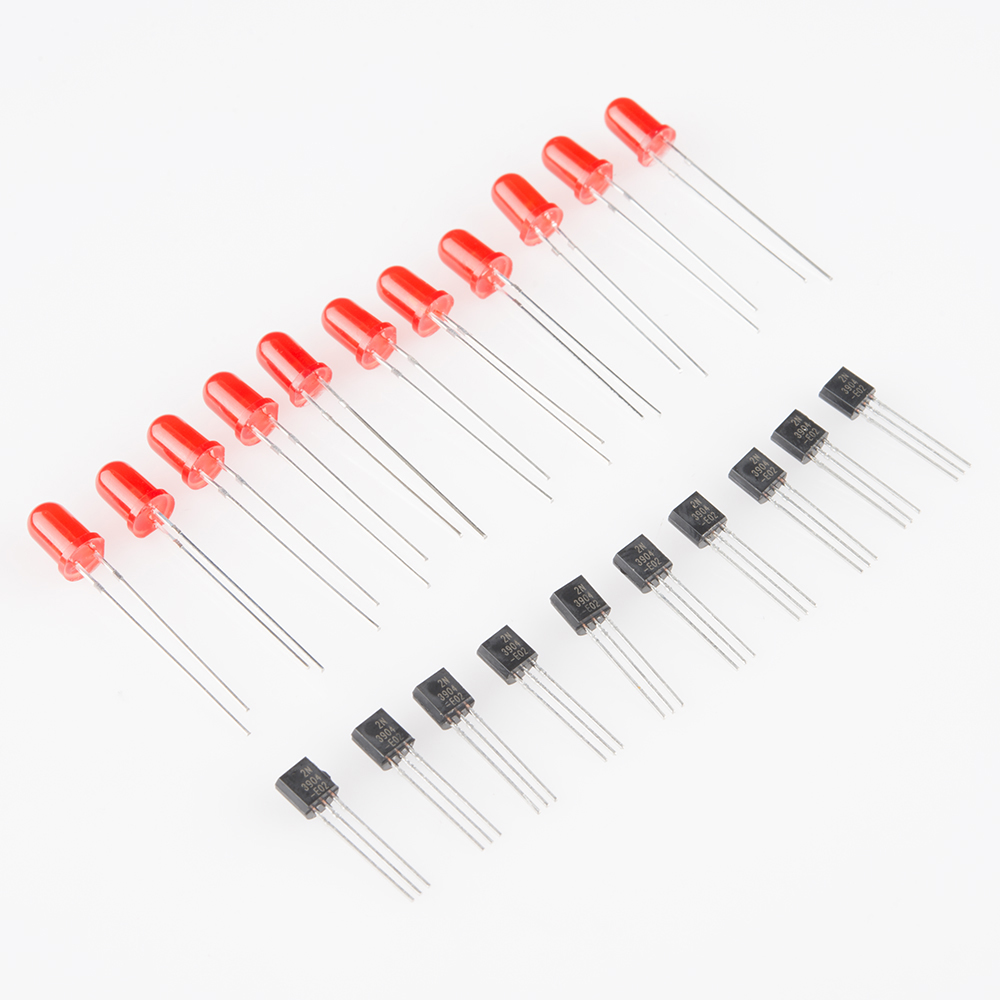
- Eleven red LEDs
- Ten 2n3904 NPN transistors
Potentiometers
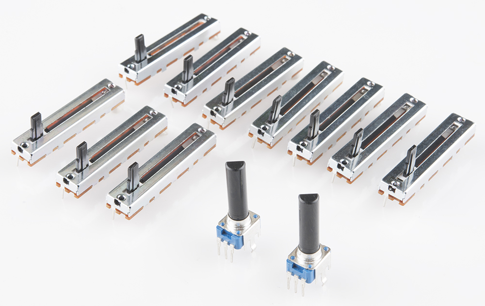
- Ten 10K Ohm linear slide potentiometers
- Two 10K Ohm rotary potentiometers
Switches

- Twelve Mini single pole, dual throw (SPDT) Switches
- One Red LED Tactile Button
Mechanical Components

- One 9 Volt Alkaline Battery
- One 9V Battery Holder
- One 5-pin right angle male header
- One 5-pin right angle female header
- One 3/8" long 2-56 Phillips head machine screw
- One 2-56 nut
If you come up short, please contact customer service, and they can set you up with replacement parts.
Electronic Assembly I - Diodes
With a PCB like this, it's usually easiest to assemble if you start with the shortest components, and work up to the tallest ones. That way, you don't have work around the bulk of the larger components.
Diodes
The silicon diodes are the shortest components, so we'll start with them. Find the Silicon diodes in the kit - they have a small orange body that looks like a glass bead, with a black stripe near one end.
The silicon diodes are installed side-by-side in the locations marked below. It doesn't really matter which one you start with.
These diodes are polarized. The glass body has a black stripe on one end, which matches up with the white stripe on the PCB silkscreen.
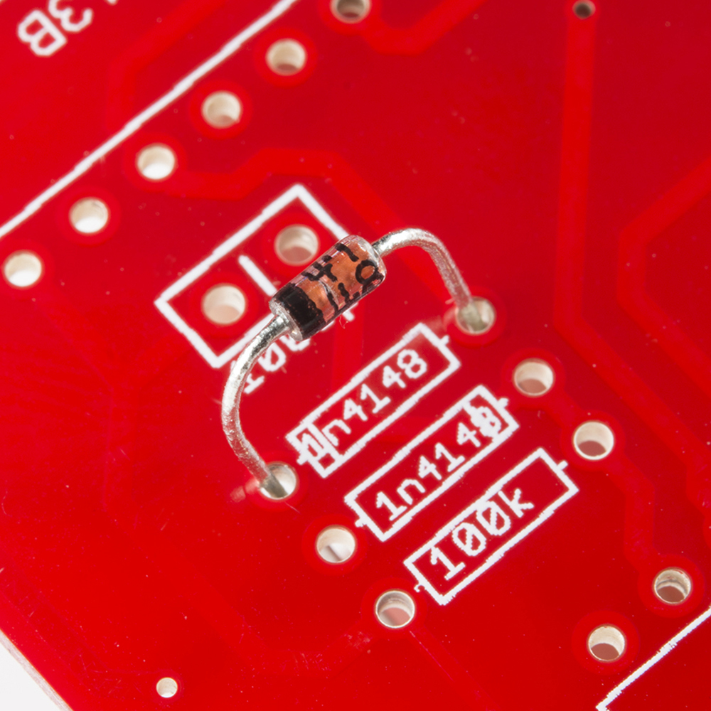
The diode gets mounted on the top the the PCB, the side with the silkscreen outline. Bend the leads so they fit through the holes, and push them through until the body sits on top of the PCB. You can bend the legs outward slightly to hold the diode while you work.
Turn the board over, and solder the diode in place. Take care to make good solder joints, with just the right amount of solder. The solder should flow evenly between the board the the lead, making a small, smooth dome or cone shape. If you're not sure about your fillets, refer to the diagram in our soldering tutorial.

Once it's soldered, trim the excess leads near the fillet.
Install the other diode next to it. Again, it should be inserted with the stripes on both the body and PCB aligned, which faces the opposite direction of the first diode.
After both silicon diodes are in place, let's install the Schottky diodes. (Okay, they're a tiny bit larger than the resistors, but not so large that it will interfere with later steps).
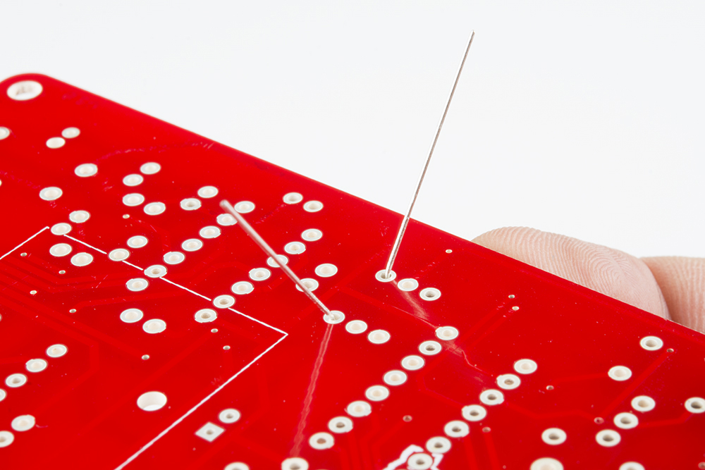
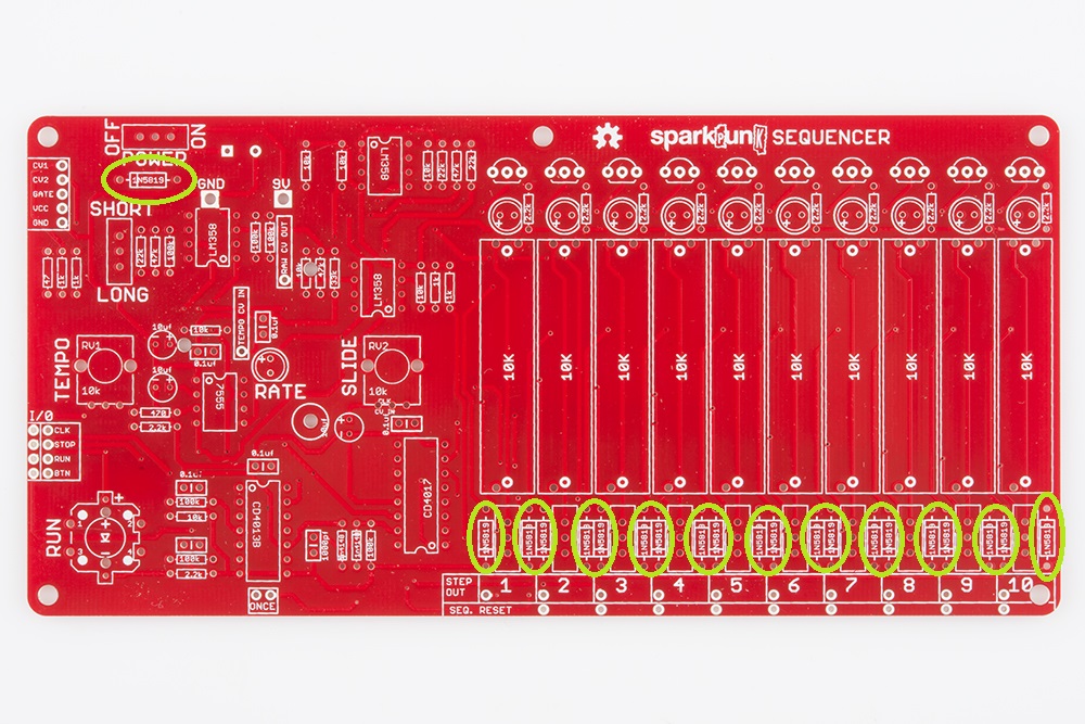
The Schottky diodes are black cylinders with a gray or white stripe on one end. There are a lot of them on the board - the first towards the upper left corner, and the others placed in pairs across the bottom-right edge of the board.
Like the silicon diodes, The Schottkies are polarized. Match the stripe on the body with the stripe on the PCB. Take care that the ones across the bottom edge of the board are oriented correctly - they alternate in polarity, with every other one being the opposite of it's neighbor.

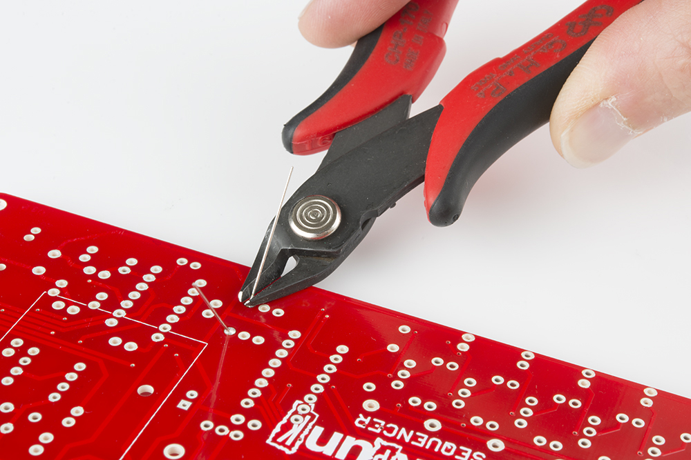
Solder them in, and trim the excess leads.
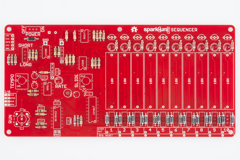
With all the diodes installed, your PCB should look like this (click picture to enlarge):
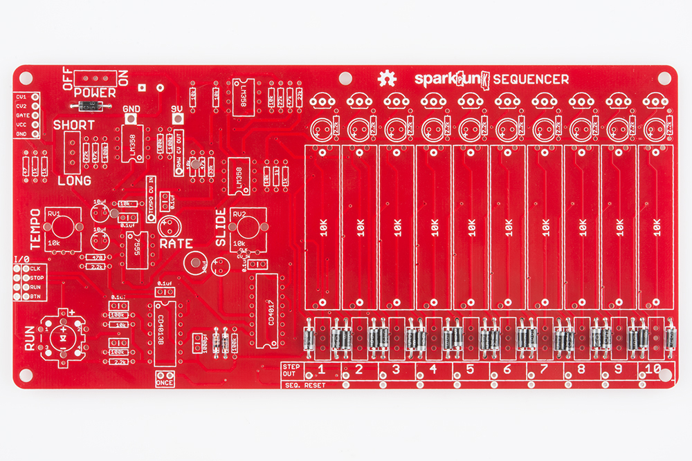
Before proceeding, take a moment to verify that you have the stripes on all the diodes oriented correctly. They will be harder to fix when all of the other components have been installed.
Lather, Rinse, Repeat
The pattern we've established here (insert, solder, trim) will be repeated for each of the other components on the PCB.
Electronic Assembly II - Resistors
Resistors are not polarized - they can be installed in either orientation. We'll install the resistors in order of increasing resistance value. For each resistor value, we'll insert, solder, and trim the excess leads just as you did with the diodes.
There are quite a few resistors on this board. We'll install all of them in the following steps. To keep the process organized, we'll start with the lowest value, and work up the the highest. The resistor values are indicated by the colored stripes on the resistor body. The color codes are noted in the photo captions below, but if you'd like a more thorough explanation of how the codes work, you can find that in our Resistor Markings Tutorial. You can also verify ther resistor values using a multimeter.
The resistor locations on the PCB are marked with silkscreened numbers inside the outline of each resistor. Once you've deciphered the markings, you can find the corresponding value written on the board, and install the resistor there. This may sound daunting, but we've got helpful pictures with each value highlighted in the following steps.
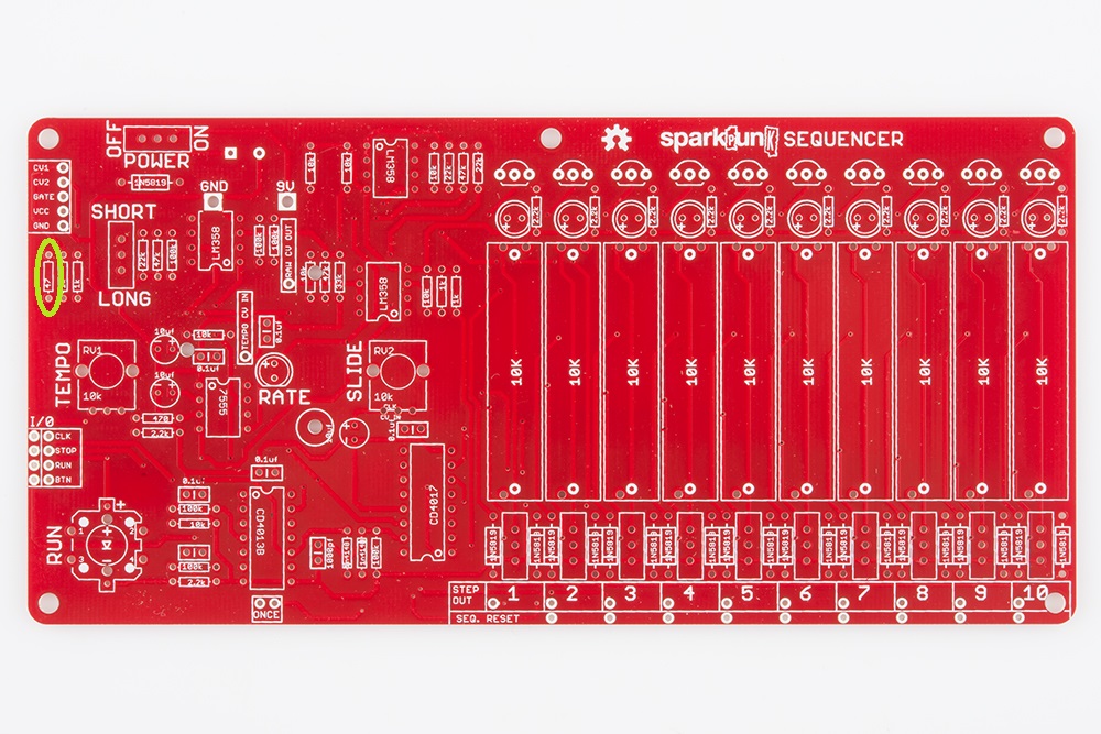
47 Ω
The lowest value resistor is the 47 Ω resistor. It is located near the left edge of the PCB, as seen below:
470 Ω
The next resistor is the 470 Ω. It's located on the left, near the center of the board, shown here:

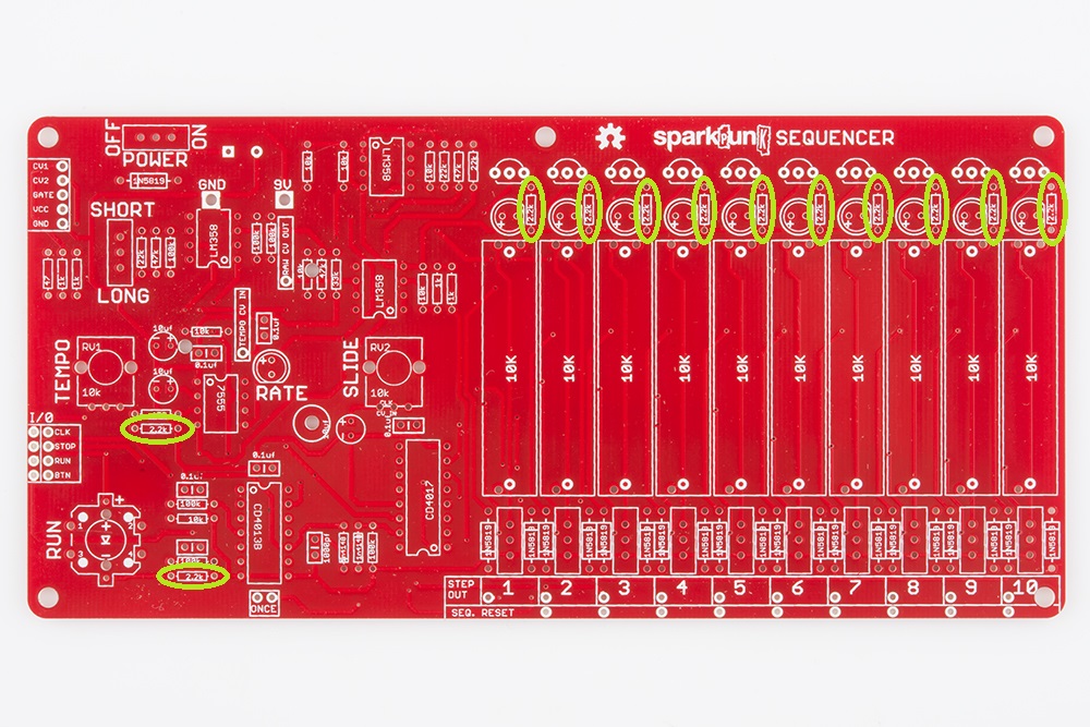
2.2K Ω
There are a bunch of 2.2K resistors on the board - twelve to be precise. Two are on the left hand side, and the other ten are across the top right edge of the board, highlighted below:
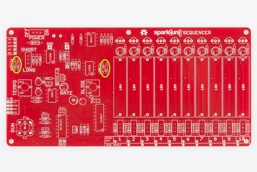
1K Ω
There are four 1K Ω resistors. Two of them are placed as a pair near the left edge, and the other two are paired near the center of the board. They're all circled in this photo:
10K Ω
There are seven 10K Ω resistors, spread across the left side of the board.
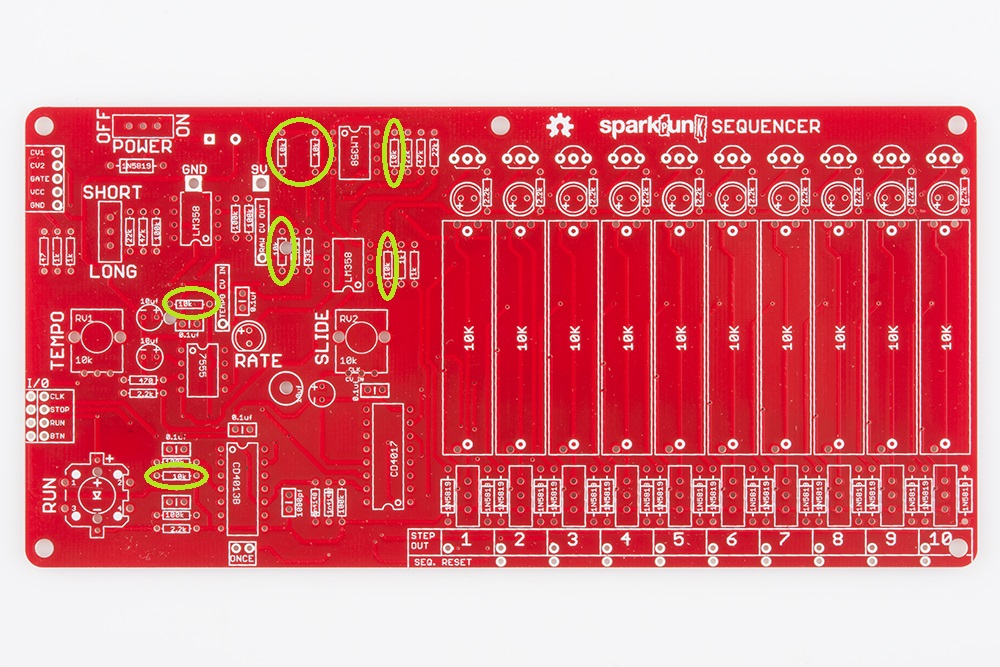
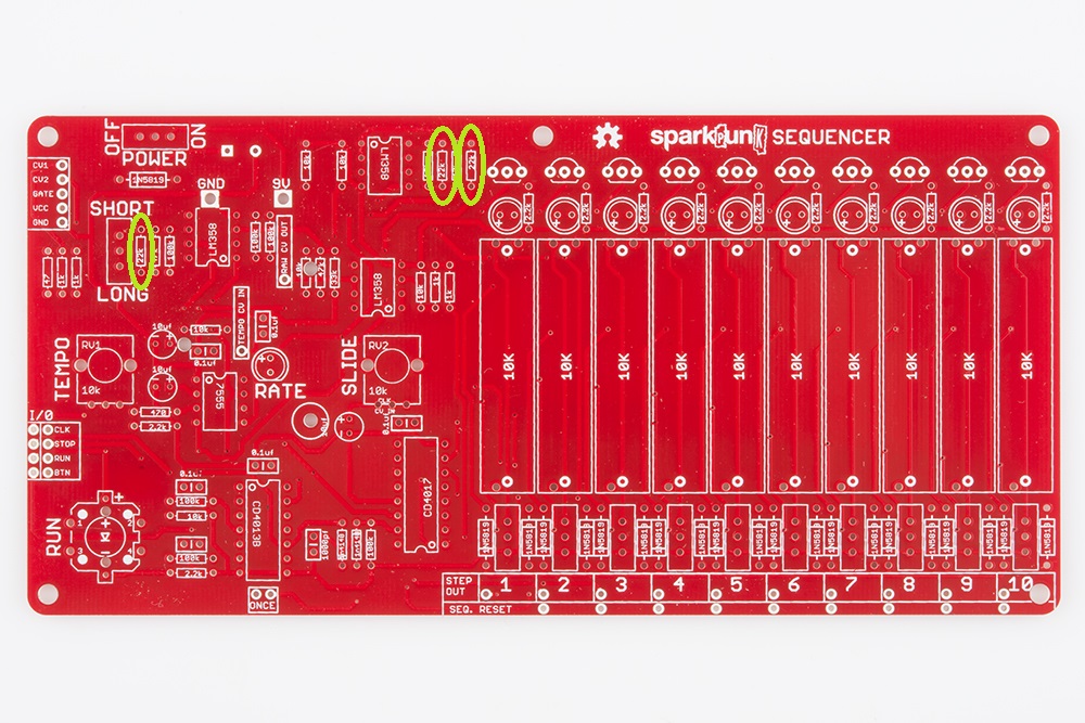
22K Ω
There are three 22K Ω resistors, two near the top center, and one towards the top left corner.
33K Ω
The single 33K Ω resistor is located here:

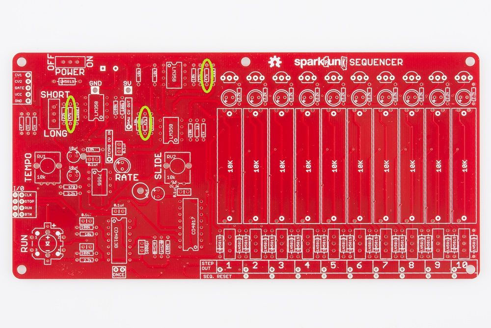
47K Ω
The three 47k Ω resistors are spread across the upper left of the board, as depicted below.
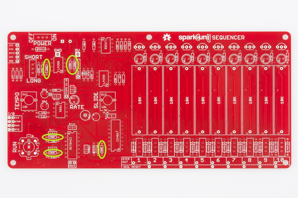
100K Ω
Finally, we reach the 100K Ω resistors. There are six of them, distributed around the left side of the PCB.
At this point, all of the diodes and resistors have been installed. Your board should look like this (again, click on the picture for a higher resolution version):
Take a moment to look around your work area for loose resistors or diodes that you might have missed. All of the resistors and diodes should be mounted on the PCB
Electronic Assembly III - Capacitors
Capacitors
With the resistors complete, we'll move on to the capacitors (also known as "caps" for short). The shortest caps are the ceramic ones - the ones in this kit are little orange/yellow blobs, each with two leads.
Like the resistors, the ceramic caps are not polarized - they can be installed facing either direction.
0.1µF Ceramic Capacitors
There are six 0.1µF caps. The caps themselves are marked 104. The values are printed on the side of the caps, but in very tiny print - in some cases, it might be so small as to be nearly invisible. A magnifying glass can help. Be careful with these caps as there is also a 1nF cap. It's almost the same size as the 0.1µF caps, but it is marked 102.
The 0.1µF capacitors should be located as shown below:
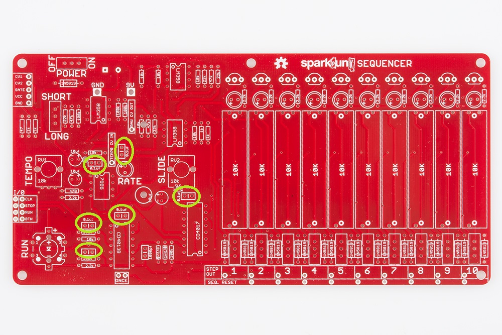
You'll notice that the lower left cap is missing the value marking on the silkscreen - it is indeed a 0.1 μF cap.
The procedure for these caps is similar to the components we've already installed. Insert, solder, then trim.
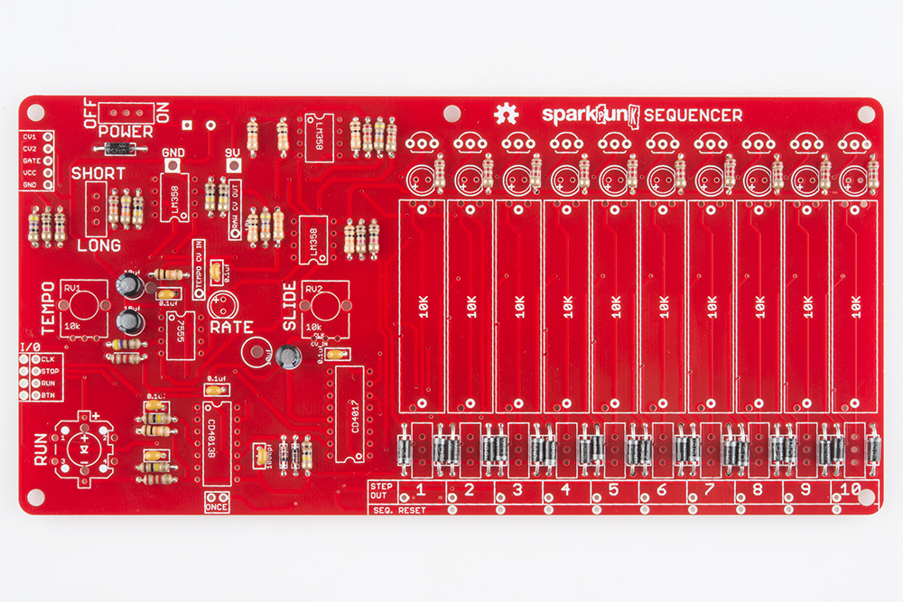
1nF Ceramic Capacitor
There is one 1nF (sometimes also known as 1000 pF) cap. It's marked 102, and it is located here:

Electrolytic Caps
Electrolytic Capacitors are the small cylinders that look like tiny soda cans. They are polarized, having a positive and a negative lead. The positive lead is usually longer than the negative, and the negative side is usually marked by a stripe on the body of the capacitor itself. The pads on the PCB are marked with both "+" and "-" symbols. Be sure to line up the "-" on the body with the "-" on the PCB.

There are three of the 10 µF Capacitors on the board, found in these locations

Check Your Progress
At this point, all of the smaller passive electronic components have been installed. Your board should look like this:
Odd Man Out
There is still one cap remaining, the large 1000 μF electrolytic. It gets mounted on the back of the board, but we'll hold off on that for the moment, as having it on the back makes the board rather cumbersome. We'll revisit it in the electromechanical section.
Electronic Assembly IV - Integrated Circuits and Semiconductors
ICs
The chips, or integrated circuits (IC's) on this PCB are all in through-hole Dual Inline Packages (DIP). The IC's are polarized, and need to be installed in the proper orientation.
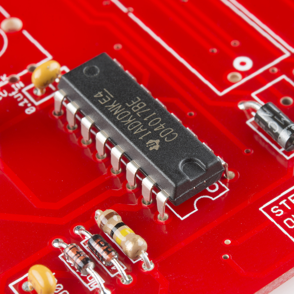
The IC polarity is indicated on the body of the IC - usually with a notch embossed in one end, though sometimes with a small dimple in one corner. These indications line up with the silkscreen markings on the PCB, which are rectangles with a small half-moon cut out of one end, and a nearby dot. Line the notch on the IC up with the half-moon in the silkscreen, as you can see below.
Inserting ICs into the board should be fairly straightforward. Sometimes the legs in the ICs have been bent such that they don't fit right in. If so, carefully straighten them to match the holes.
To solder an IC down, it can help to quickly solder down legs on opposite corners, which helps hold the chip in place while you solder the remaining legs. Take care that you don't overheat the chip, or create solder bridges between adjacent legs. It can help to work in a zig-zag pattern, back and forth between the rows of legs.
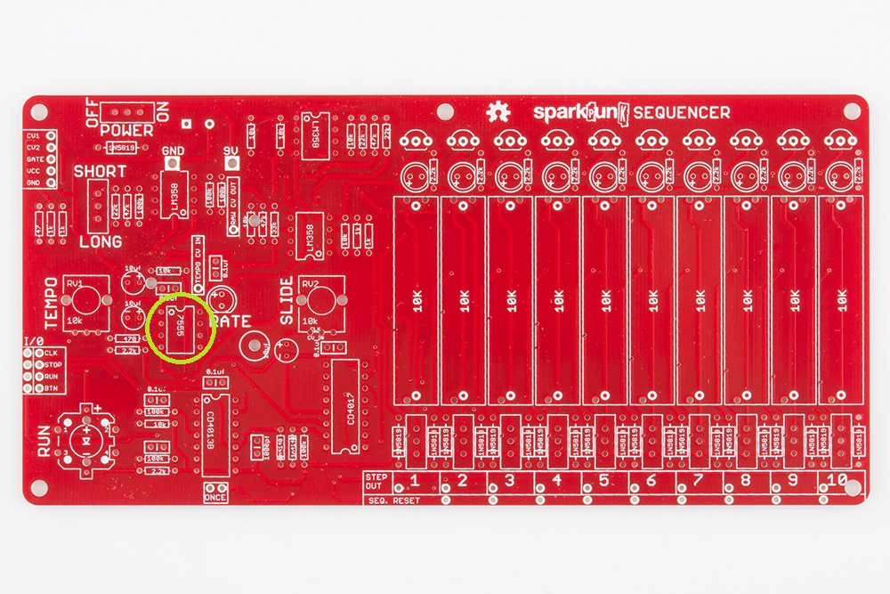
7555
The first chip to go on is the 7555 timer. There are several similarly sized chips in the kit, so take care to read the markings on the ICs.
The 7555 is located here:
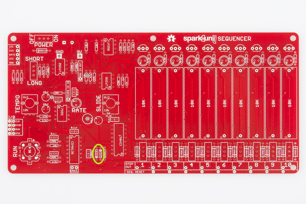
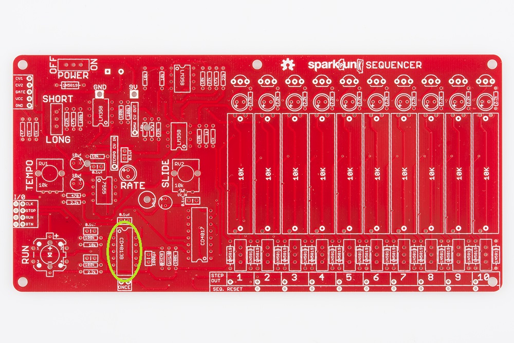
CD4013BE
Now that we've warmed up with a small IC, we'll move on the the larger ones.
Find the CD4013BE dual flip-flop, and install it here:
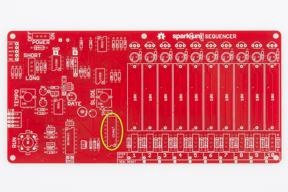
CD4017BE
Next is the CD4017BE decade counter.
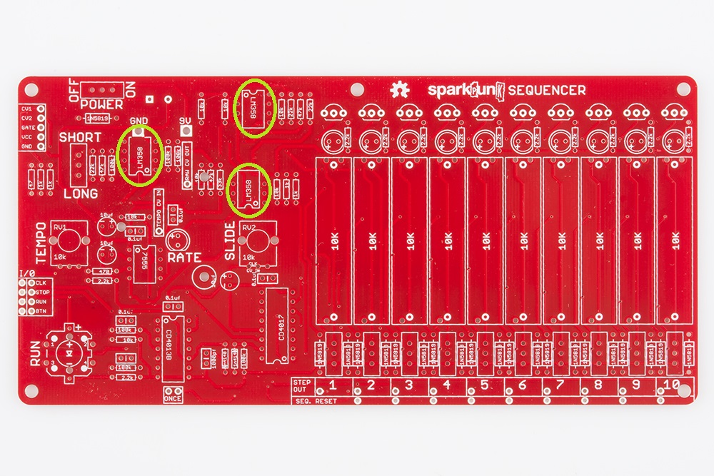
LM358
Rounding out the ICs are the three LM358 dual operational amplifiers. They are located towards the top left corner of the board, as shown here:
Semiconductors
After the ICs are down, we move on to the other semiconductors.
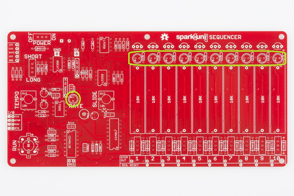
Transistors
There are ten transistors, all 2n3904's. They each have three legs, and a cylindrical body with a flat on one side.
The transistors are installed across the top-right edge of the board.
Align the transistors by matching the flat side of the body with the flat of the silkscreen mark. You may need to bend the leads apart a bit so they fit into the board.
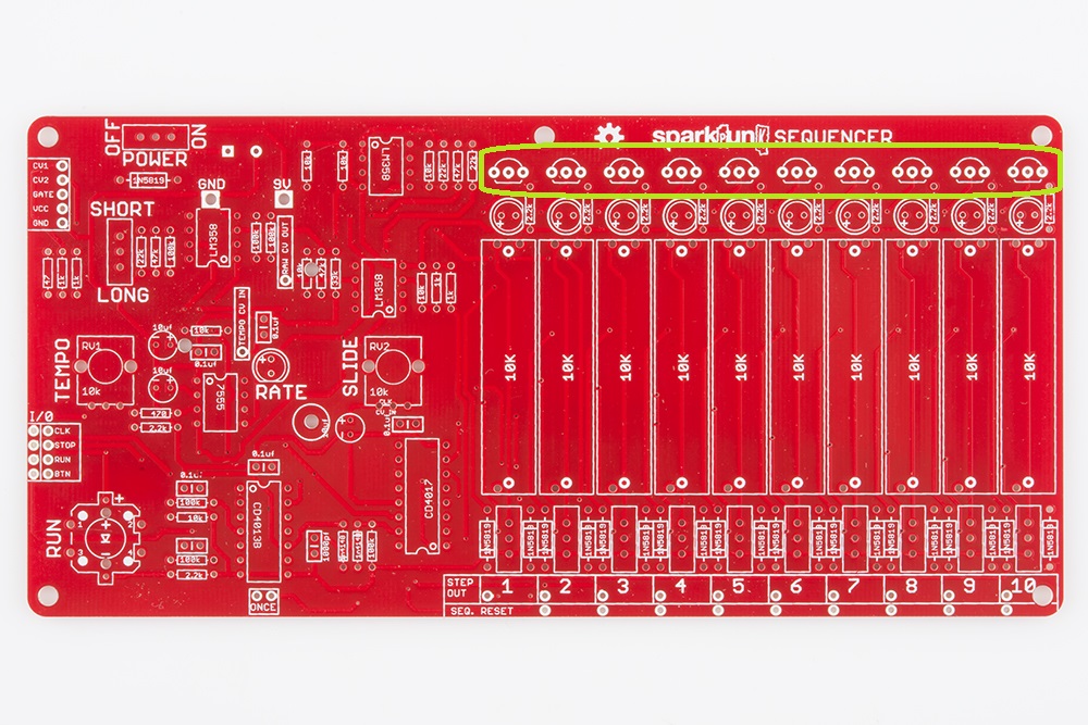
LEDs
The eleven LEDs are located as follows:
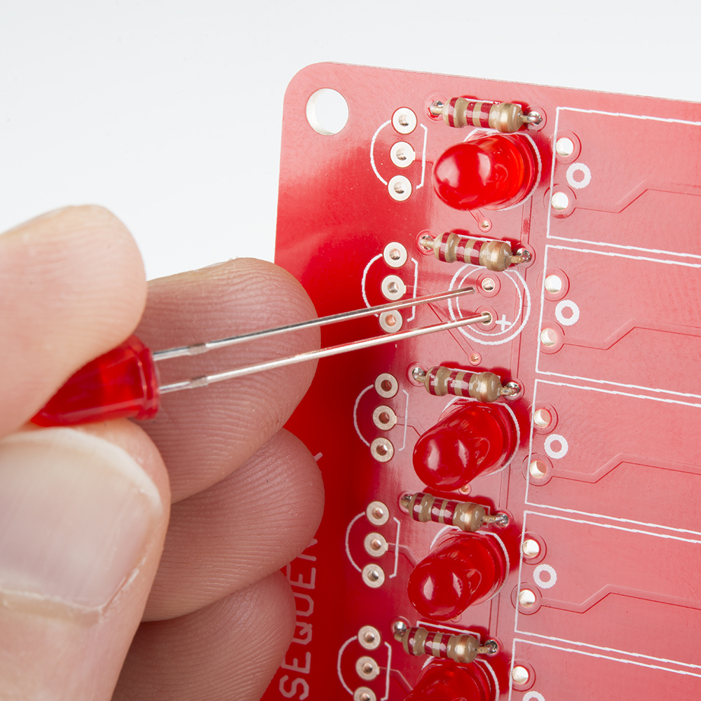
The LEDs are also polarized. The polarity is indicated two ways on each LED - the positive leg (the anode) is longer than the negative leg (the cathode). There is also a small flat spot in the base of the LED to denote the negative lead. Both of these are indicated in the PCB silkscreen. As you can see below, the longer lead is going through the hole marked +, which leaves the flattened side aligned with the flat edge in the silkscreen.
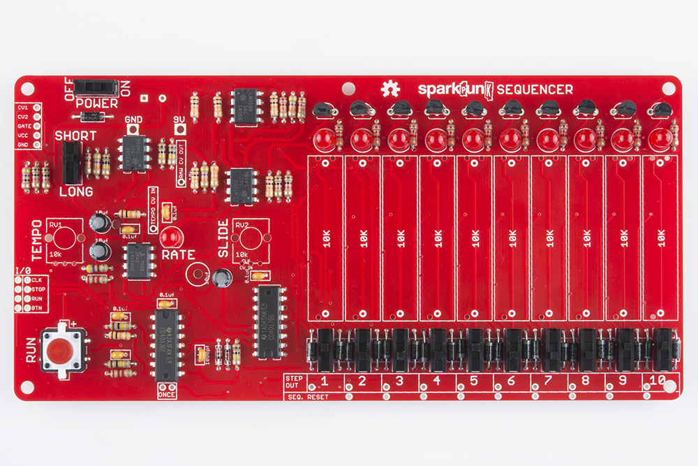
Almost Done
The SparkPunk Sequencer is nearly complete. There are only a few more components to be installed.
Before moving on, check you work against the photo below.
Assembly V - Electromechanical
Controls
Tactile Switch
The first control is the tactile switch, which is located in the lower left corner of the PCB.
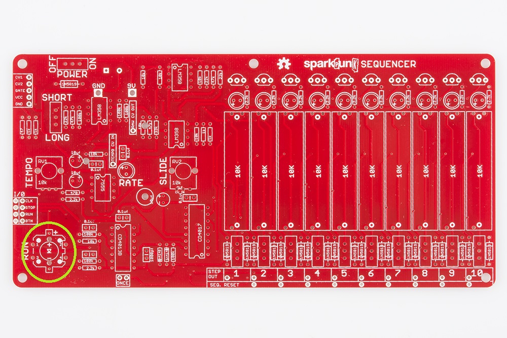
Unlike regular tact switches, this one has an LED in it, so that it can light up when the sequencer is playing. Therefore, the switch is polarized. There is a small "+" sign embossed in one of the white plastic tabs. This matches up with the "+" on the board, as seen in the photo below.

The tact switch legs are already formed so that it will lock in place while you solder, but it can take extra effort to get those legs into the PCB holes. Apply gentle pressure until they snap through, and the body of the switch sits squarely on the PCB. Then solder it in place.
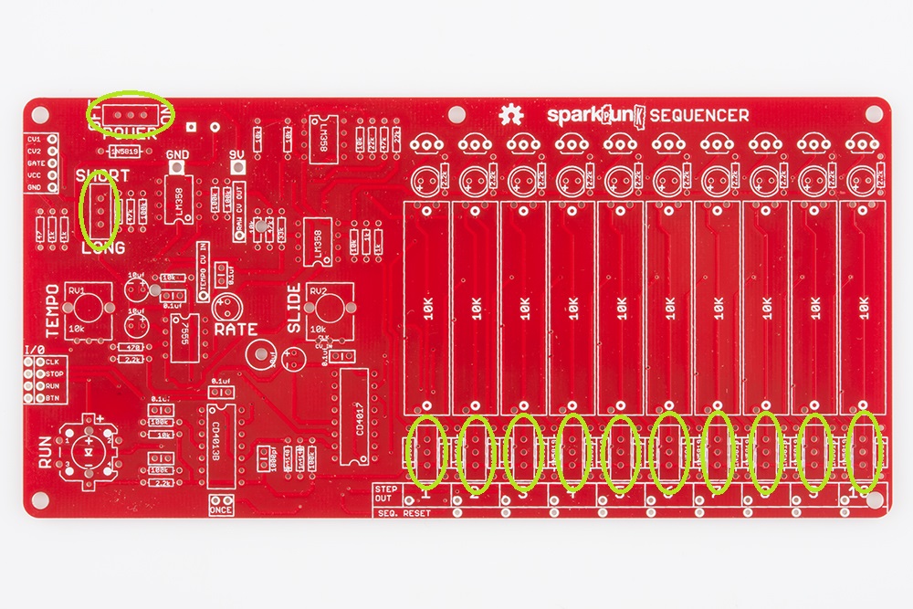
Slide switches
There are twelve small single-pole, double-throw (SPDT) slide switches on the SparkPunk Sequencer. The first two are near the top left corner, and the other ten are arrayed across the lower right edge of the board.
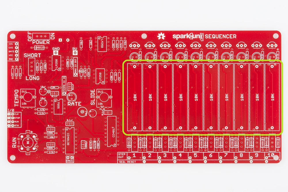
Slide Pots
The ten slide potentiometers are the largest components on the board. They are located in a row across the right side of the PCB.
If you take a close look, they only fit in the board one way - one end has a single contact, while the other end has two, which matches the hole pattern on the PCB.
Because they are so large, they can be difficult to keep aligned while soldering. A piece of removable tape can help hold them in place while you work. We had blue painter's tape handy, so we used that.
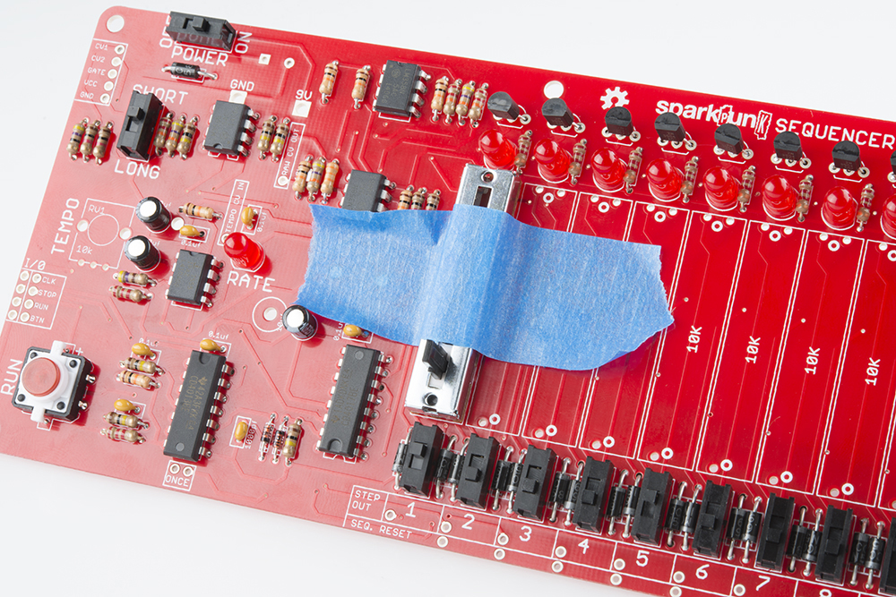
Tape a single slider in place, then solder it down. You can work your way across the board, taping each slider down and soldering it in turn.
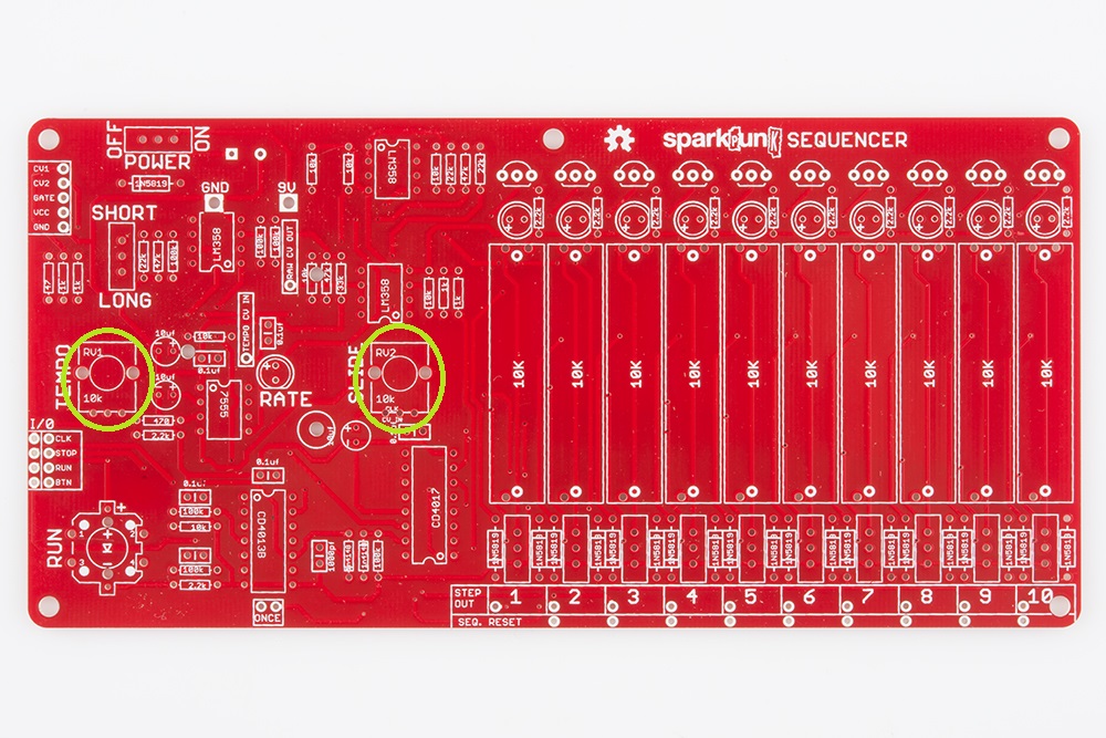
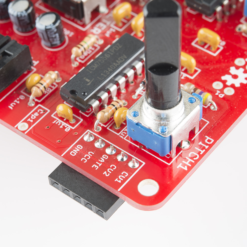
Pots
The rotary potentiometers are the tallest component, so they mark the end of the components on the top of the board.
They're not polarized, but they’ll only fit on the board one way.
It takes some care to get them into the board. If the leads or tabs have been bent in transit, they will need to be straightened out to fit the PCB. To insert the pot, start by lining up the smaller electrical legs, then push the two large tabs into the holes. The tabs are a tight fit - gently rocking the pot from side to side can help. When inserted correctly, the posts on the back of the pot will sit flush on the top of the PCB.
When you solder them in, first solder down the large tabs for stability, taking care that the pot stays flat on the board. Then solder the other connections.
There are two rotary pots on the PCB, both 10K linear taper (marked "M-B-10K" on the back). They go as follows:
Top Side Completion
We're reaching the home stretch, but before we move on to the power components, let's check that all of the parts we've covered thus far are in the correct place. Take a few minutes to compare your board to the photo below. Check that no components have been omitted, and that all of the polarized components (diodes, ICs, LEDs, and electrolytic capacitors) are facing the proper direction.
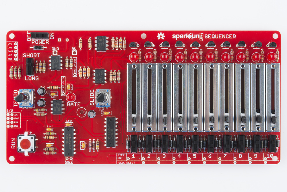
The reason for checking at this point is that we're about to mount components to the back of the board, which will make it harder to rework anything you may have missed.
Power
Battery Box
The battery box is mounted on the back of the PCB. It has two contacts that go through the board.
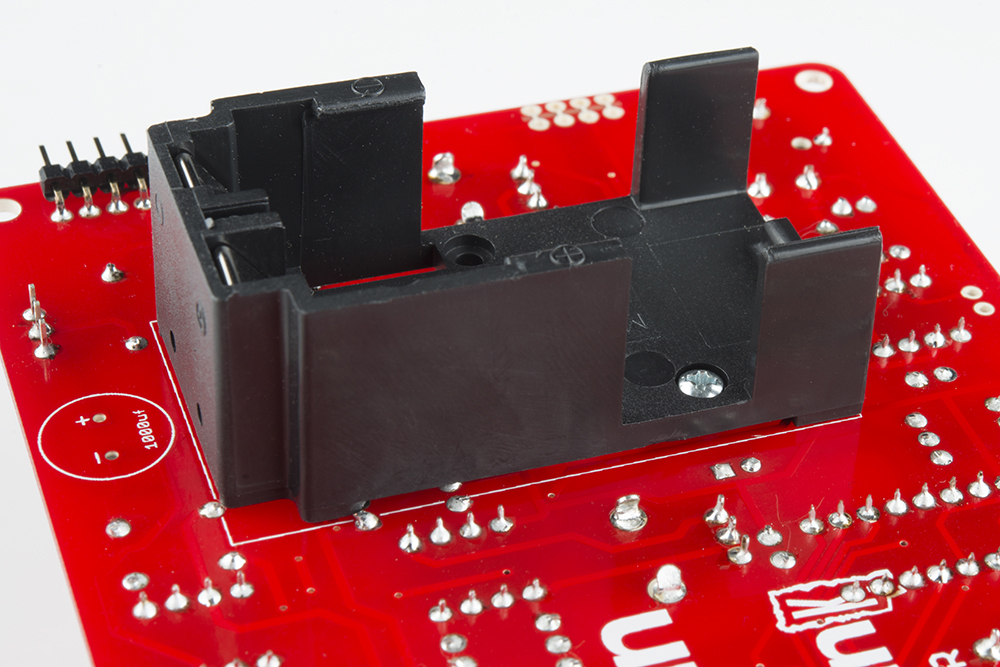
It is secured with a small nut and bolt. The bolt should be inserted from the inside of the battery compartment, and secured with the nut on the front side of the board.
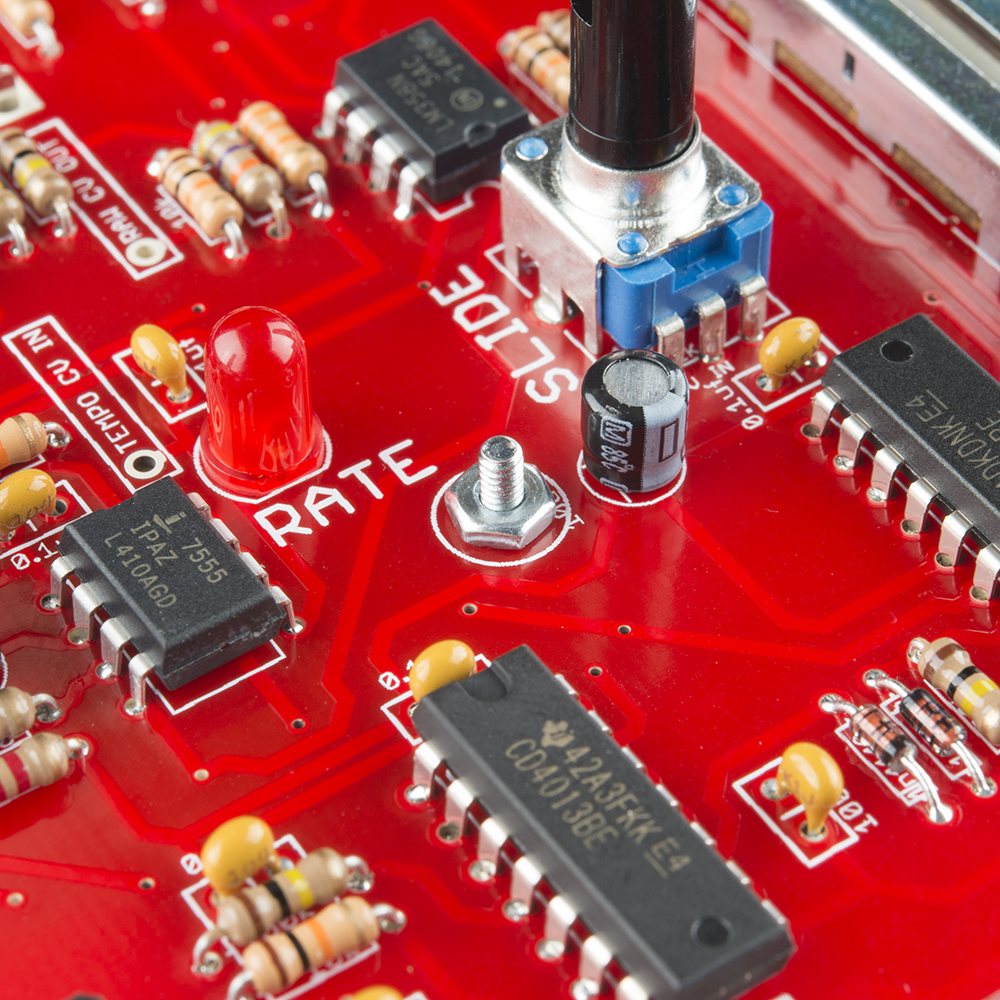
Tighten the bolt, then solder the two leads to the front of the PCB.
1000μF Capacitor
Now it's time for the capacitor we skipped a couple sections ago. It also goes on the back of the PCB. Like the smaller electrolytics, it is polarized, and needs to be oriented correctly, by matching the lead near the "-" sign on the body up with the PCB pad marked "-", as shown below:

Like the battery box, the 1000 µF cap is soldered to the front of the board.
Connectors
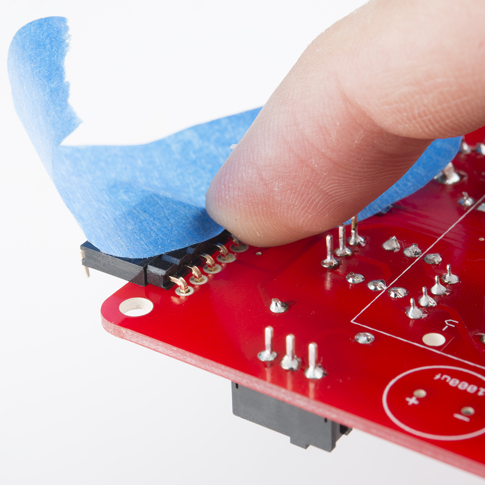
The last set of components are the connectors, a pair of 5-pin right angle headers, one male, and one female. This is the connection that joins the Sequencer to the SparkPunk Sound Generator. It needs to be aligned correctly so that the two can easily plug together.
To get the proper alignment on the connectors, we will use one connector as a jig to hold the other in place. Plug the connectors together, face-to-face. Then place the connector on the back of the sequencer, and tape it in place, as shown below. As you can see, the male side of the connector is on the Sequencer, leaving the female side for the Sound Generator.
Solder the connector to the top of the PCB.
Then remove the female side of of the connector, and solder it onto the Sound Generator. As with the sequencer, it goes on the back of the PCB, soldered to the front. You can use tape to hold it on place while you solder.
Check Your Work
This marks the end of the soldering portion of this kit. You can verify your progress against the picture below.

The only remaining component should be the 9V Battery.
If everything checks out, we are now ready to move on to testing the sequencer.
Testing/Troubleshooting
We will test the sequencer in several progressive stages.
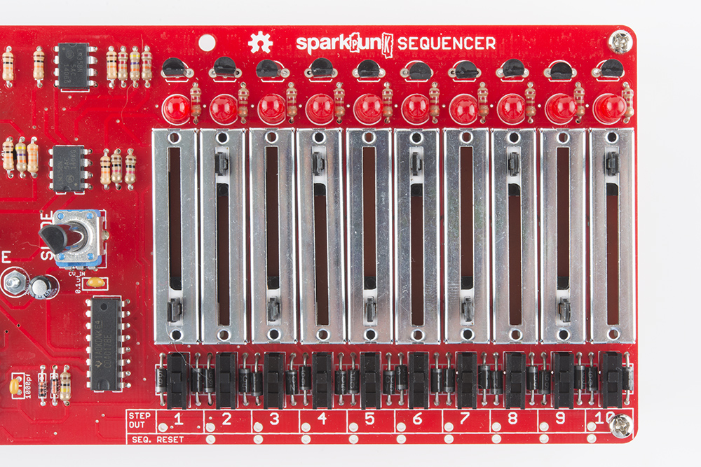
You’ll notice that as the board got assembled, a lot of the text and legends in the silkscreen got covered up by the components. The remaining text explains the function of the nearby controls. We’ll denote those labels using text in boxes like this.
Sequencer Alone
We'll begin by testing the sequencer by itself.
The first test is a smoke test. Install the battery in the battery compartment. There are a small “+” and “-” embossed in the box that will match the corresponding marks on the battery. The battery should slide into the holder, and be held in place by the tab at the back end. If it doesn’t fit easily, make sure that you’ve got it aligned properly.
Turn on the power switch. The first step LED, above the first slider, should light up solidly (not blinking or flickering).
Feel the ICs - none of them should be warm to the touch.
Press the RUN button. The button should illuminate, the RATE led should start to flash, and the step LEDs should start chasing from left to right.
Turn the TEMPO pot. It should vary the rate of the chasing and flashing - slower when counterclockwise, and faster when clockwise.
Stop playback by pressing the RUN switch again. The button LED should go out, and the chasing and flashing should stop. The LED over the first step should be lit steadily again.
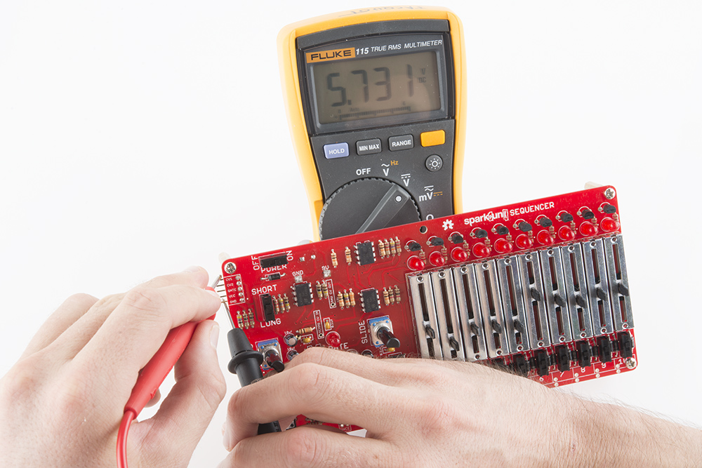
If you have a voltmeter handy, you can use it to test the output port. Set the meter to measure volts DC, in the 1 to 10 V range. Place the black lead on the GND pin, and the red lead on the CV1 pin. While the sequencer is stopped, adjust the slider on the first step. You should see the voltage vary between approximately 7.5 V at the bottom of it's travel and .7 V at the top.
If any of these tests are failing, check out the troubleshooting suggestions below.
Integrated System Test
Once the basic tests above indicate that the sequencer is functional in isolation, we're ready to test it in conjunction with the Sound Generator.
First lets connect everything:
- Plug the Sound Generator into the Sequencer by joining the 5-pin headers.
- Put a 9V battery in the sequencer - it will power the Sound Generator.
- Plug speakers or headphones into the Sound Generator.
Turn on the sequencer. It should power up as it did before.
Verify that the sound generator is set to make audible sounds by pressing its TRIGGER button. The button should light up, and you should be able to hear the sound. If it's silent, revisit the testing section of the SparkPunk Hookup guide.
Next, set the sequencer controls as follows:
- Turn on all ten of the step switches, near the
1to10labels across the lower right edge of the board. - Pull all of the sliders to the bottom of their travel.
- Set the
LONG/SHORTswitch toLONG. - Turn the
TEMPOcontrol fully counterclockwise.
Press play. The step LEDs should chase, and the RATE LED should blink. You should hear a continuous sound.
While it is playing, set the LONG/SHORT switch to SHORT. The continuous sound should now be broken into shorter bursts that correspond to the illumination of the RATE LED. With the TEMPO control fully counterclockwise, the pulses should be about 1/4 second long, repeating every 1/2 second.
While it continues to play, turn the SLIDE control all the way down, and start adjusting the sliders. You should be able to hear the effect that the sliders have on pitch. When a step is indicated by the step LED, the slider for that step controls the pitch from the sound generator. Eventually, you'll want to wind up with sliders alternating between all the way up, and all the way down, as shown below.
Turn the LONG/SHORT switch back to LONG, and experiment with adjusting the slide time. You should be able to hear the notes gliding from pitch to pitch.
Next, turn the step switches off one by one, and listen as holes of silence open up in the audio output.
Finally, press RUN to stop the playback.
We will describe exactly what these controls are doing in more detail in the next section.
Troubleshooting
The first thing to check is the control settings on both units - if they're set to generate silence, you won't hear anything! You can check that the sound generator portion is working by pressing its TRIGGER button. If the sequencer plays, but you aren't hearing anything, check the volume control, sound generator waveform switches and the sequencer step trigger switches.
If you're still having trouble with the above tests, you can start troubleshooting by following this checklist.
- All solder connections should have neat fillets - small cones or domes of solder that smoothly join the component leads to the PCB.
- Verify battery orientation & freshness.
- Check that all polarized components are installed correctly. These include:
- The electrolytic capacitors
- The diodes
- The ICs
- The Battery
- Verify the volume is turned up
- Verify that output is connected
If things still aren't working, try contacting Sparkfun's friendly technical support team.
Usage
We skimmed through the basic functionality of the sequencer while we were testing - you probably already have a good idea what the controls do. But if you'd like to understand it in more detail, then keep reading.
The Controls
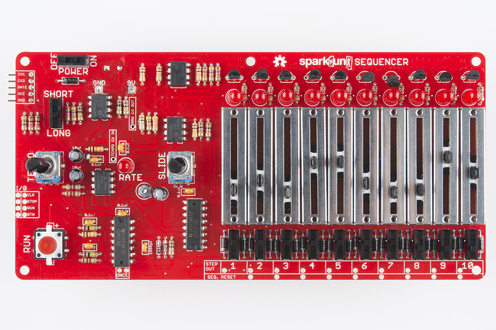
The following picture denotes the controls on the sequencer.
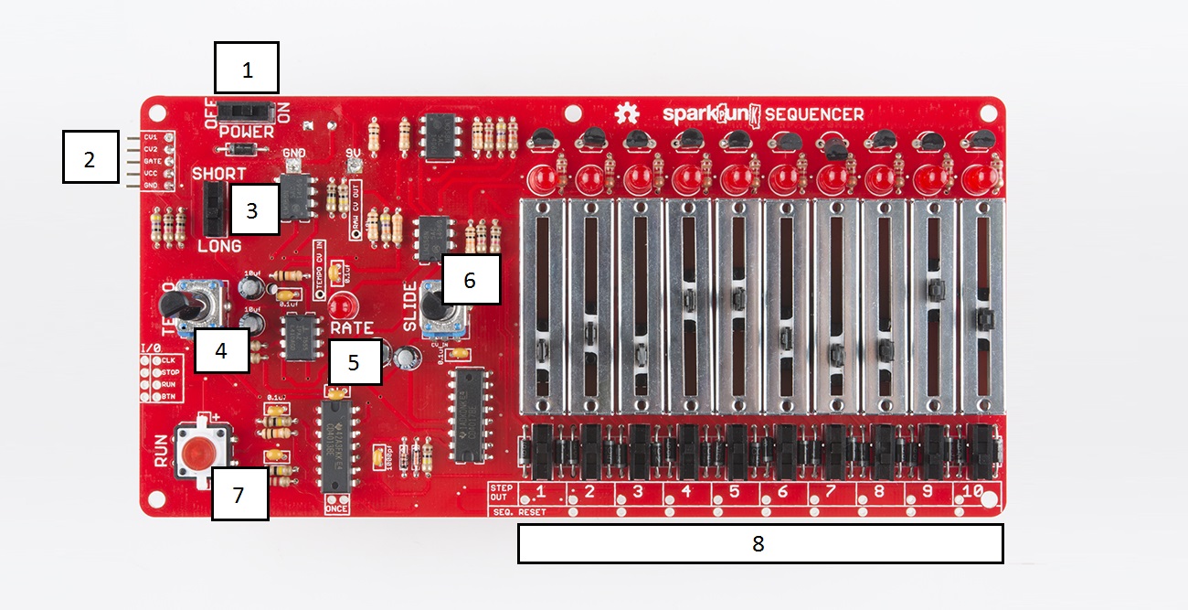
- Power Switch - Turns the the sequencer on and off.
- Sound Generator interface connector - 5-pin header that connects to the SparkPunk Sound Generator. It provides power, pitch, and trigger signals to the attached SparkPunk.
- Long/Short Switch - Determines the length of notes triggered by the sequencer.
LONGnotes sound for the full length of the step, andSHORTnotes are half the step length. We'll illustrate this in more detail below. - Tempo Knob - Controls the clock, determing the rate at which the sequencer advances from step to step.
- Rate LED - Blinks to display the clock rate.
- Slide knob - Controls the time it takes for the sequencer to slide from note to note. See the diagram below for a more detailed description.
- Run switch - Starts the clock, which in turn causes the sequence to advance between steps. It also contains an LED that lights up while the sequencer is running.
- ** 10 steps** - Each step has several controls.
- Step indicator LED - Denoting the active step of the sequence.
- Pitch slider - The pitch control voltage is determined by the slider setting on the active step.
- Trigger switch - When this switch is on, the note for this step will sound, with the length determined the the
SHORT/LONGswitch. If the trigger is off, this step of the sequence will be silent.
An analog sequencer like this is intended to be a hands-on, interactive musical tool. Having physical controls makes it easy and fun to experiment with compositional ideas.
Sound Generator Interface
The heart of the sequencer is the interface to the Sparkpunk Sound Generator. The sound generator was designed so that it could simply plug into the sequencer.
All of the controls on the Sound Generator still function when connected to the sequencer. The knobs and switches control the sonic parameters, and the trigger switch triggers sounds. At the same time, the sequencer controls the sound generator using two signals, the pitch control voltage and the gate. As the sequence plays, the circuit selects one column of controls at a time, and analog voltages that correspond to the control settings are driven to the output port.
Pitch Control Voltage
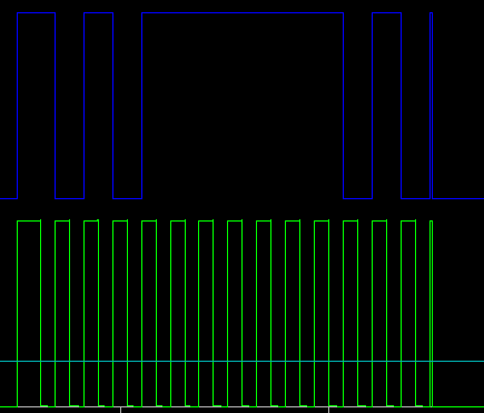
The sliders on the sequencer control the pitch of the sound generator. The following diagram illustrates how slider positions are translated to the control voltage output:
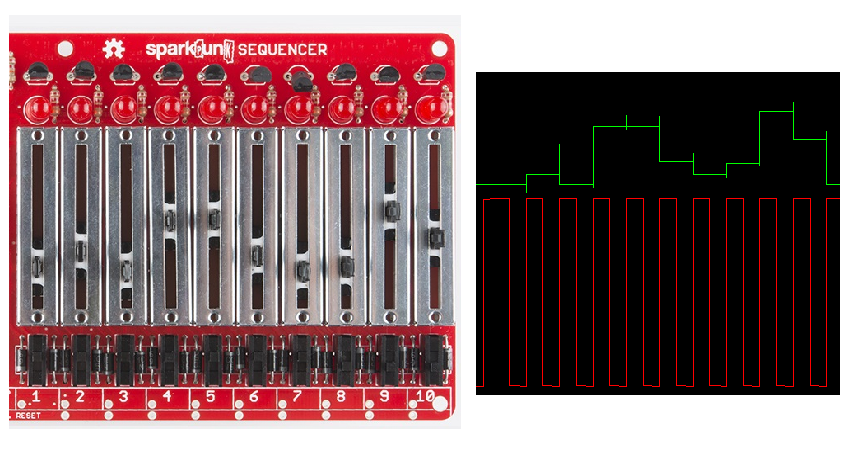
By comparing the slider positions to the green trace, you can see how they are converted into voltages. Each slider is selected in turn when a rising edge is seen on the clock, the red signal.
Slide
You'll notice that the control voltage above changes very quickly when a clock pulse is received - the rise and fall segments are nearly vertical, with the result looking like a series of rectangles. By turning the SLIDE control up, we can slow down those transitions, causing the edges to become rounded, as you see here:
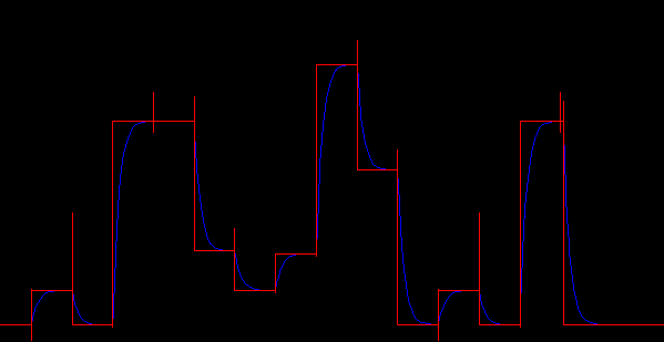
The red plot is the same control voltage pattern we saw above, and the blue is the result of turning up the SLIDE control. The more slide you add, the longer it takes to transition from one pitch to the next. The result of this is a musical effect known as portamento or glissando, which is commonly used by instruments like the trombone or slide guitar.
The slide is generally more audible in the LONG setting than SHORT. To understand why, let's take a look at the gate signal.
Gate
In electronic terms, a "gate" or "gating function" is a DC signal that corresponds to the presence of another signal. It can be generated as an output by a circuit (such as the gate output from the Sound Detector), or as an input to a circuit. In electronic music, a gate signal controls whether a tone generator is running.
The switch on each step of the sequencer allows you to control the gate signal when that step is active. When the switch is off, the gate signal is not driven, and the sound generator will be silent. However, when the gate switch is on, there are two possible results, as determined by the SHORT/LONG switch.
When the switch is set to LONG and the step switch is on, the gate for a step lasts the entire step. In the diagram above, the clock is in green at the bottom, and the gate is in blue at the top. If adjacent steps are on, the gate is continuous - a legato articulation, as shown by the long plateau in the gate signal.
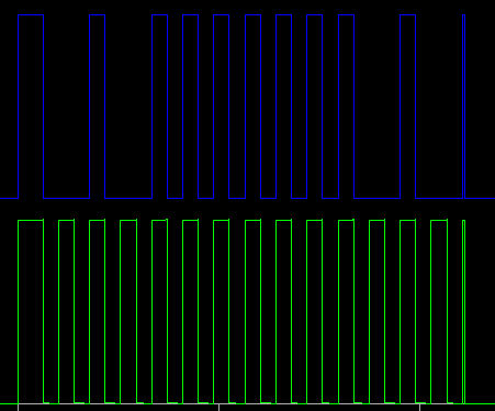
In contrast, a short gate is only half a step long. Even if adjacent steps are on, there will be a half-clock duration of silence between them. In the diagram above, the step switches are set the same as the previous example, but the length switch is set to SHORT. The long plateau has been chopped into a number of small chunks.
Power Sharing
One final item worth noting: both the Sequencer and Sound Generator have battery holders and power switches. The units have a common power bus that allows either device to power the other. Only one battery needs to be installed, and the power switch on the unit with the battery will switch the pair on and off. The bus uses diode protection to keep the batteries from charging each other if both are present.
Diving Deeper
At this point, we've covered the assembly of the SparkPunk Sequencer, and basic usage with the Sound Generator. Like the Sound Generator, the sequencer in intended to be adapted, modified and customized. One of those modifications is both easy and very useful.
A lot of western music built around rhythmic groupings of 4, 6 or 8, so builders might find that the 10-step sequence length is hard to use. Therefore, we'll cover a quick modification, which allows you to shorten the sequence to fewer steps.
Across the lower right edge of the PCB are pairs of solder pads - simply bridge the pair of pads to cause the sequence to reset when that step is reached.
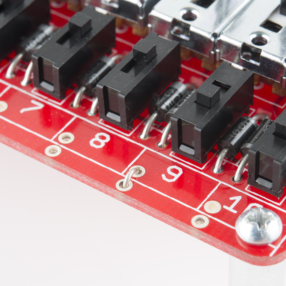
You'll bridge the pads that are one step beyond what you want as the last step - as shown above, a wire on step nine shortens the sequence to 8 steps. If you don't want to make a permanent connection, you can install snappable headers, then use jumper shunts to make the sequence length adjustable.
Resources and Going Further
Resources
- The sequencer is intended to control the SparkPunk Sound Generator. Should you need the link, here's the SparkPunk Sound Generator Hookup Guide
- Design files for the sparkPunk can be found on GitHub
- The GitHub files include Spice simulations that run in LTSpice
- SFE Product Showcase
For more information about how the SparkPunk Sequencer works, modifications and other applications, check out the Theory and Applications Guide
SparkPunk Sequencer Theory and Applications Guide
If you're interested in parts that complement the SparkPunk Sequencer, take a look at these:
- Red Stove Knob
- Black Stove Knob
- Red Chickenhead Knob
- Black Chickenhead Knob
- Small GTE Knob
- Medium GTE Knob
- Large GTE Knob
- Standoffs and 4-40 bolts
Going Further
- Raymond Scott is largely recognized as the inventor of the step sequencer, which he called the "circle machine." You can hear some examples of it in these videos, and learn more about the man and his music at his website.
- We've also got a tutorial for a similar digital device, the Auduino Step Sequencer.
- Nic Collins' Handmade Electronic Music book is a good introduction to musical circuits, with a number of breadboard projects you can build from scratch.