SparkPunk Hookup Guide
 Byron J.
Electronic Assembly III - Capacitors and ICs
Capacitors
The next tallest components are the ceramic capacitors - they're usually little orange/yellow blobs with two leads.
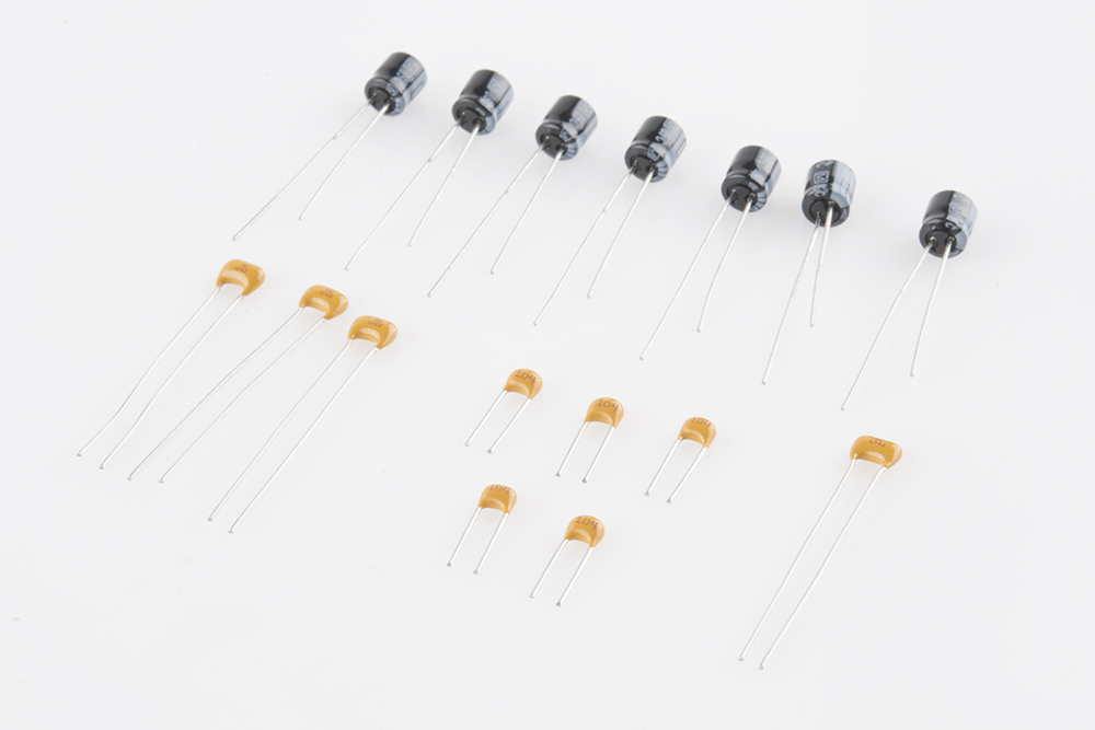
Like the resistors, the ceramic caps are not polarized - they can be installed facing either direction.
The values are printed on the side of the caps, but in very tiny print - in some cases, it might be so small as to be nearly invisible. A magnifying glass can help, or you can figure out which is which by counting the number of each.
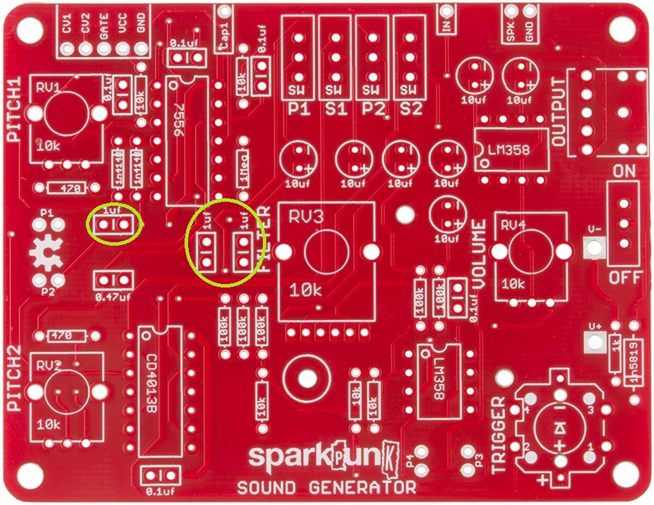
1µF Ceramic Capacitors
There are three 1µF caps, which are marked 105. They are installed here:
0.1µF Ceramic Capacitors1µF
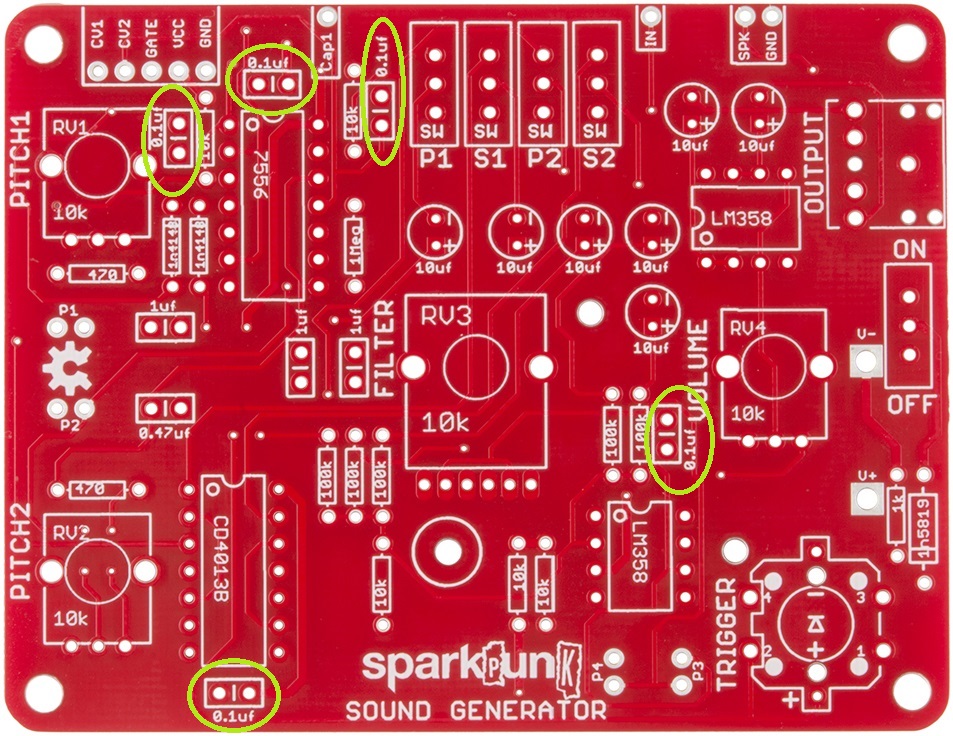
There are five 0.1µF caps. They are labeled 104, and should be located as follows:
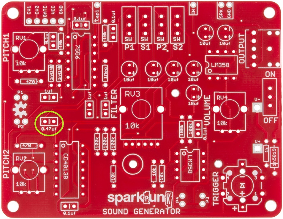
0.47µF Ceramic Capacitors
There is one 0.47 µF cap. It's marked 474, and it is located here:
Integrated Circuits
At this point, we're going to take a quick detour from the capacitors and put in the integrated circuits, because they're a little shorter than the electrolytic caps.
There are four integrated circuit (IC) chips on the SparkPunk. The ICs are polarized, usually marked with a notch at one end of the chip (if there's no notch, there's a dot or divot near one corner). Again, the PCB is marked to match the component.
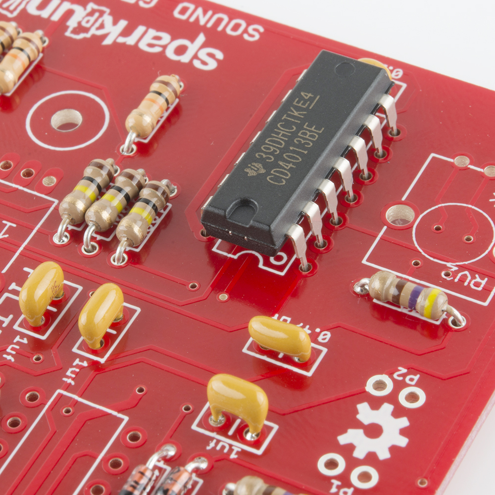
When soldering in the chips, it can be useful to start by soldering down legs that are across from each other diagonally, to hold the chip in place while you solder the other legs.
The ICM7556 and CD4013B are both 14-pin packages - take care to put each in the correct location.
Let's work from left to right, installing the chips.
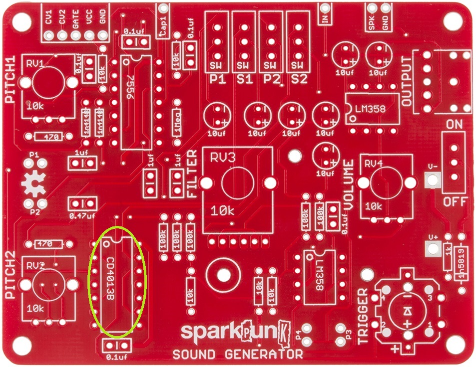
First is the CD4013B, in the lower left corner:
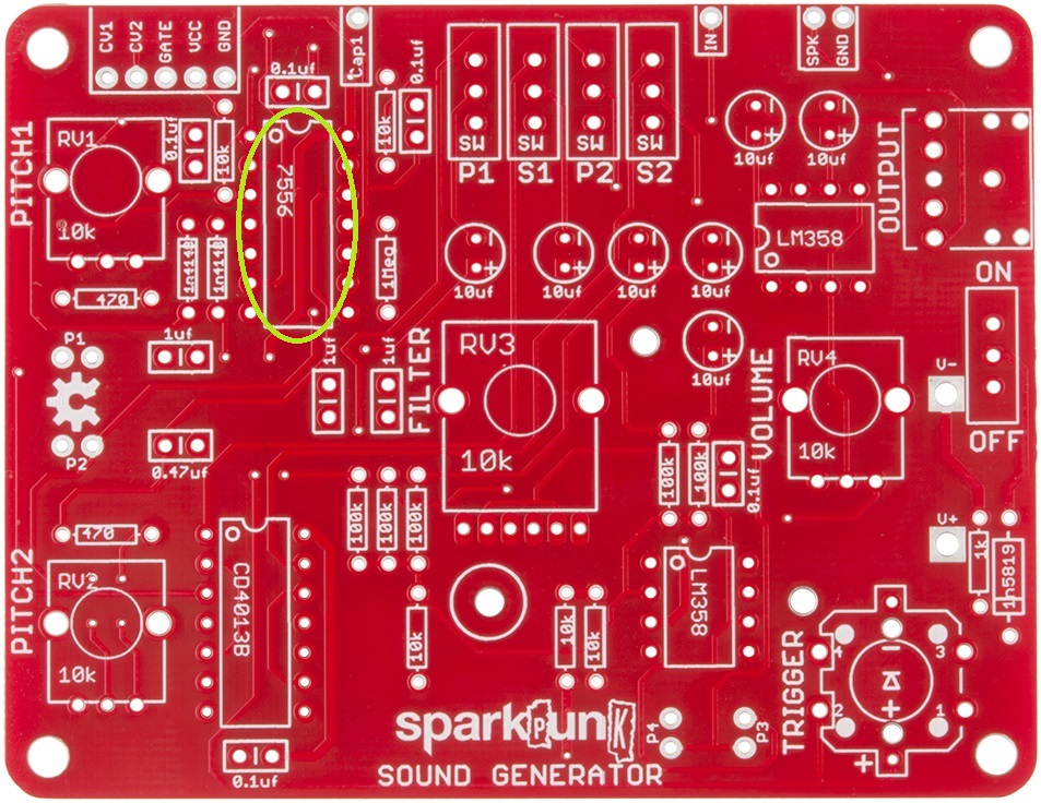
Following that is the ICM7556:
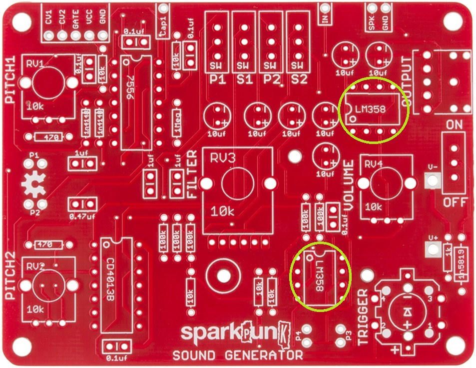
And Rounding up the ICs, lets put in the two LM358's:
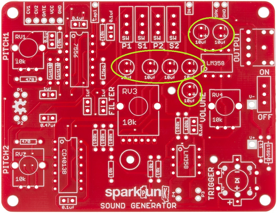
Electrolytic Caps
Electrolytic Capacitors are the small cylinders that look like tiny soda cans. They are polarized, having a positive and a negative lead. The positive lead is usually longer than the negative, and the negative side is usually marked on the body of the capacitor itself. The pads on the PCB are marked with both "+" and "-" symbols - the longer lead will go through the hole with the +. On this board, they all go in the same orientation, with the negative leg towards the top of the board.
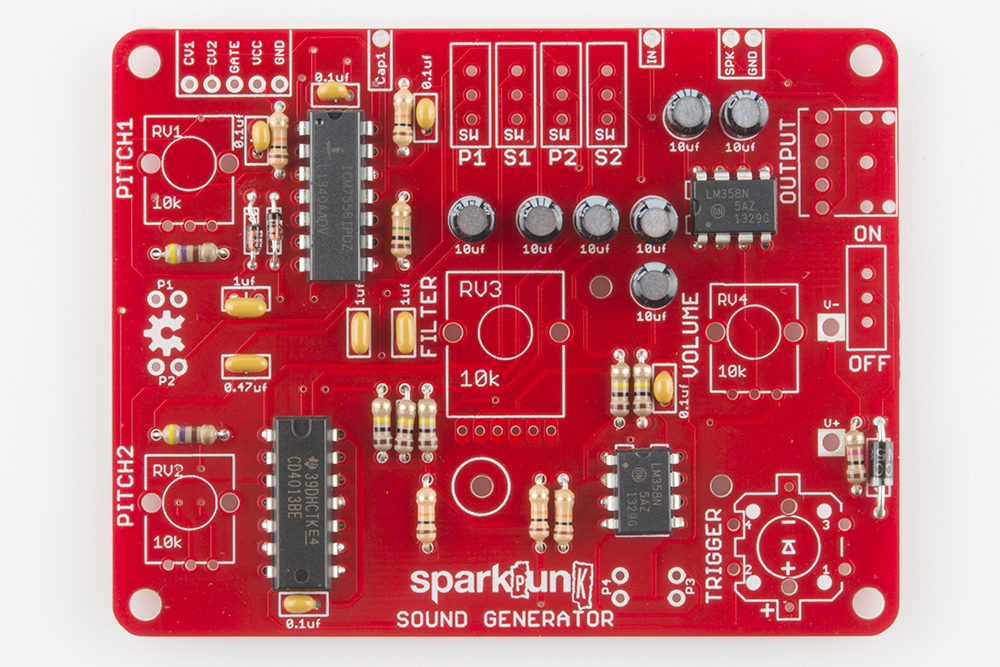
Check Your Progress
At this point, all of the shorter electronic components have been installed. Your board should now look like this:
We're almost there - there are just a few more components to install.