SparkPunk Hookup Guide
 Byron J.
Introduction
The SparkPunk kit is a sound generator in the spirit of the Atari Punk Console.
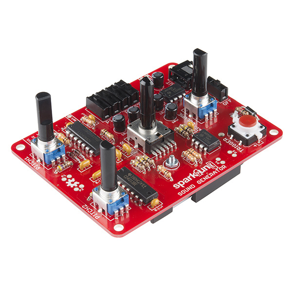
SparkFun SparkPunk Sound Kit
KIT-11177The Atari Punk Console is a circuit that was originally designed by Forrest M Mims III, originally called the Stepped Tone Generator (seen on Page 26 in his book Timer, OpAmp & Optoelectronic Circuits & Projects). It caught on with indie, lo-f, and noise musicians as a DIY project that can be played as a very simple synthesizer.
Rather than simply recreating the Atari Punk, the SparkPunk is a new design that springs from a similar foundation. It starts with a dual 555 timer IC, then adds a second tone source, sub-octaves, and a bandpass filter. With all of the knobs and switches, a lot of tonal variations are possible. As a through-hole kit, the SparkPunk can also be easily extended and modified, expanding the palette of tones even further.
This tutorial will guide you through the assembly, testing, and modification of the SparkPunk.
Necessary Tools
- Soldering Iron
- Lead-based or Lead-free solder
- Diagonal or Flush cutters
- Small Philips Screwdriver
You'll also need a set of headphones or a small speaker to test the output once the kit is complete.
Additional Tools and Supplies
- Safety Glasses
- Magnifying glass or Loupe
- PCB Vise or Third Hand
Suggested Reading
Kit Contents
Let's begin by taking inventory of the parts in the kit.
Circuit Board
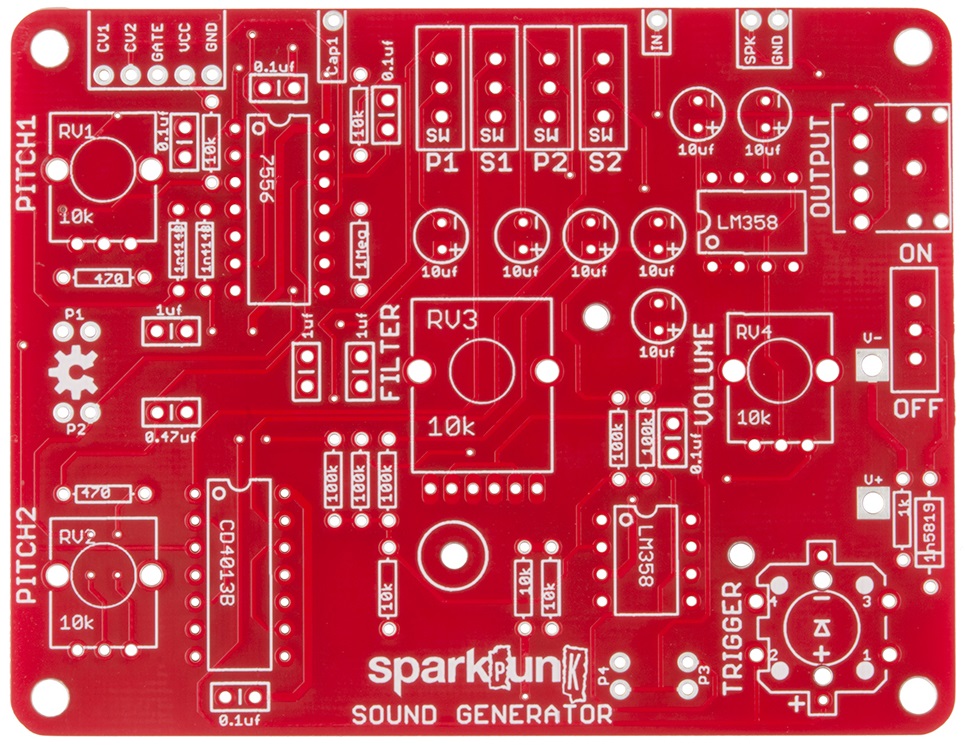
- One SparkPunk Sound Generator PCB
Integrated Circuits
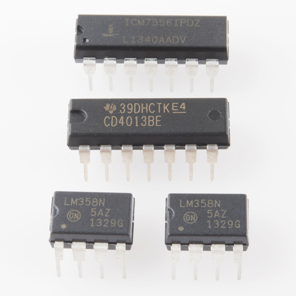
- One ICM 7556
- One CD4013BE dual flip-flop
- Two LM358 dual operational amplifier
Potentiometers
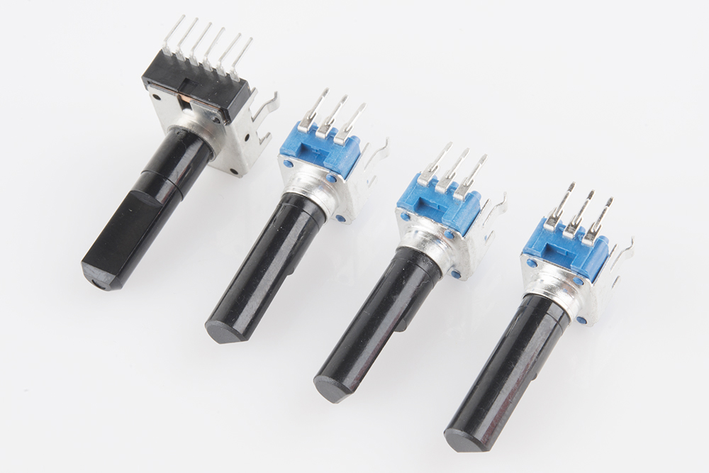
- One 10K Ohm dual potentiometer
- Three 10K Ohm potentiometer
Switches
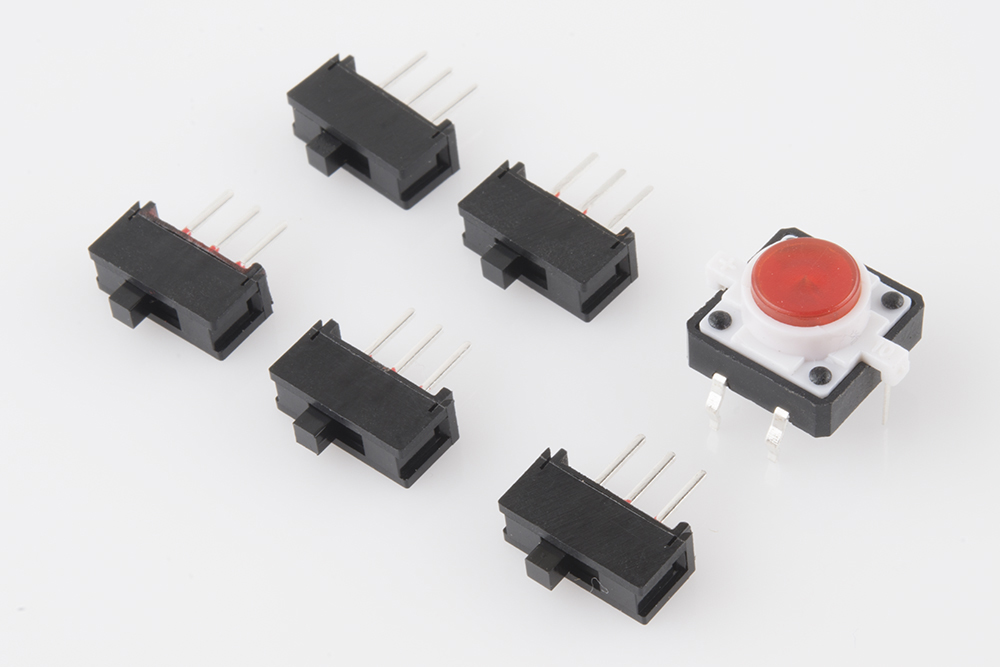
- Five Mini Power Switch
- One Red LED Tactile Button
Diodes
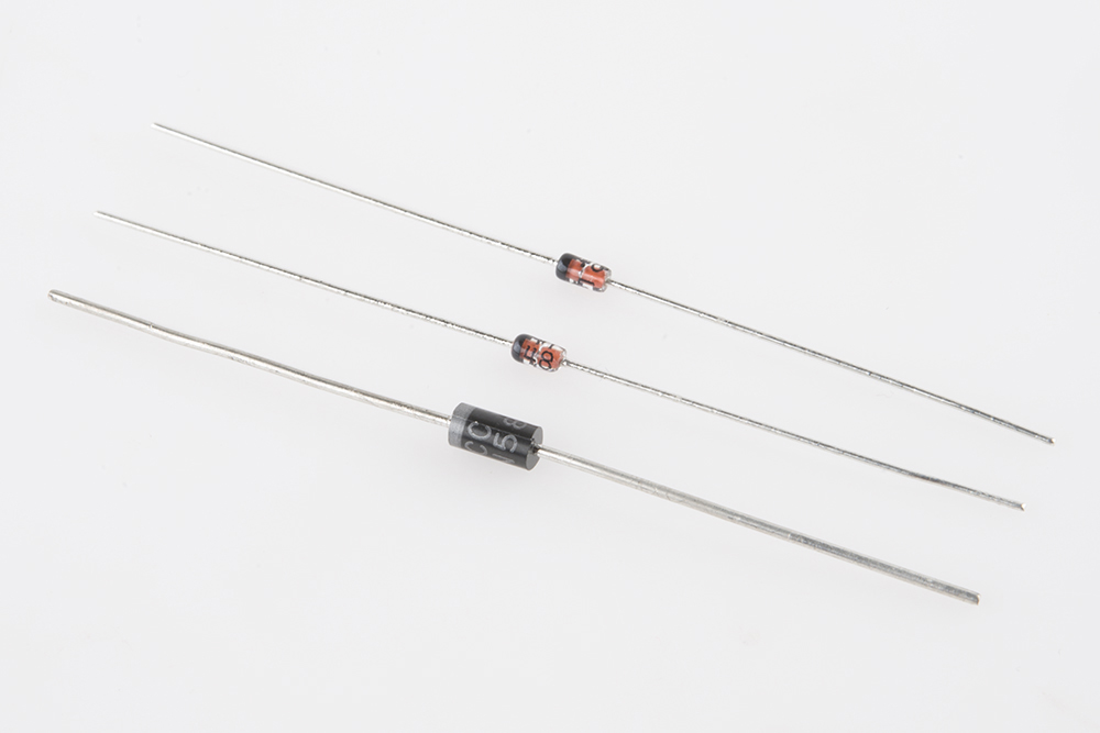
- Two 1N4148 Silicon diode
- One 1N5819 Schottky diode
Resistors
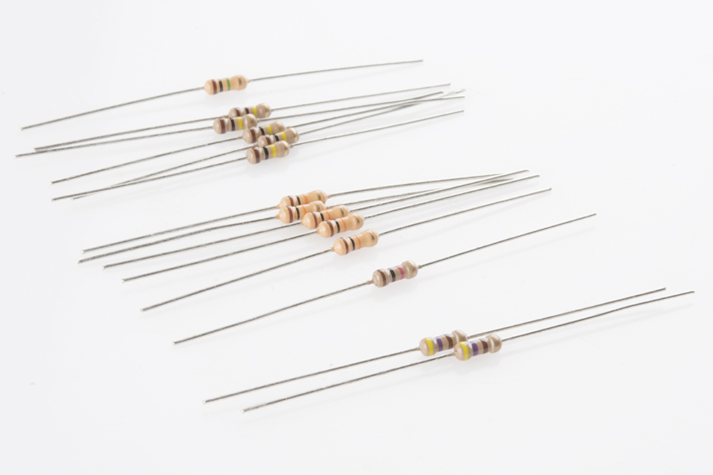
- One 1M Ohm 1/4W Resistor (Brown - Black - Green - Gold)
- Five 100k Ohm 1/4W Resistor (Brown - Black - Yellow - Gold)
- Five 10k Ohm 1/4W Resistor (Brown - Black - Orange - Gold)
- One 1K Ohm 1/4W Resistor (Brown - Black - Red - Gold)
- Two 470 Ohm 1/4W Resistor (Yellow - Violet - Brown - Gold)
Capacitors
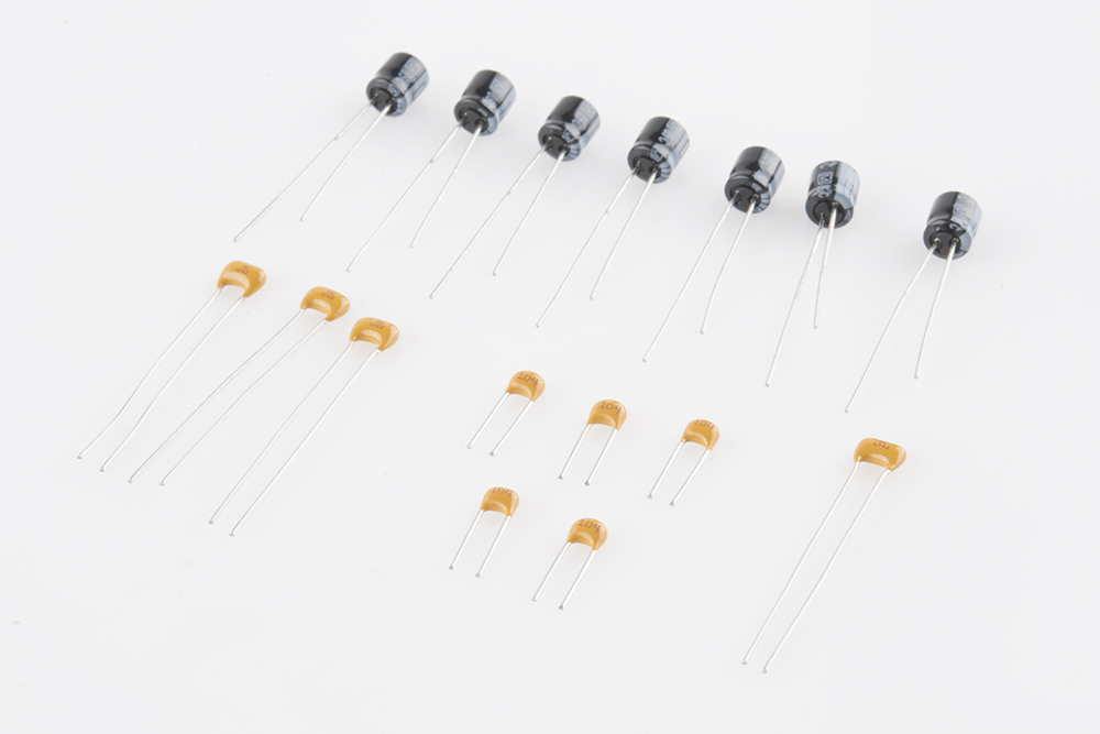
You may need a magnifying glass to read the markings on the ceramic capacitors.
- Seven 10uF 25V Electrolytic Capacitor
- Three 1uF Ceramic Capacitor (marked 105)
- Five 0.1uF Ceramic Capacitor (marked 104)
- One 0.47uF Ceramic Capacitor (marked 474)
Mechanical Components

- One 9V Battery Holder
- One 9 Volt Alkaline Battery
- One 3.5mm Audio Jack
- One 3/8" long 2-56 Phillips head machine screw
- One 2-56 nut
If you come up short, please contact customer service, and they can set you up with replacement parts.
Electronic Assembly I - Diodes
With a PCB like this, it's usually easiest to assemble if you start with the shortest components, and work up to the tallest ones. That way, you don't have work around the bulk of the larger components.
Diodes
The silicon diodes are the shortest components, so we'll start with them. Find the Silicon diodes in the kit - they have a small orange body that looks like a glass bead, with a black stripe near one end.
The silicon diodes are installed side-by-side in the locations marked below. It doesn't really matter which one you start with.
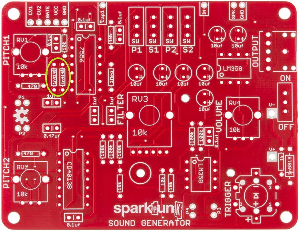
These diodes are polarized. The glass body has a black stripe on one end, which matches the white stripe on the PCB silkscreen:
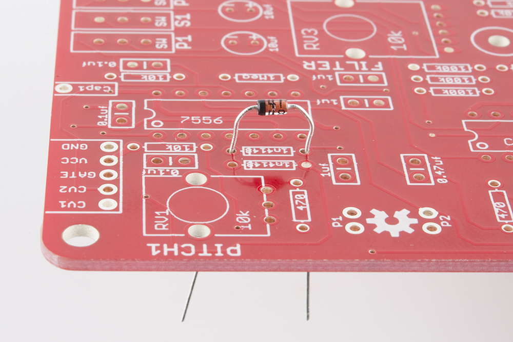
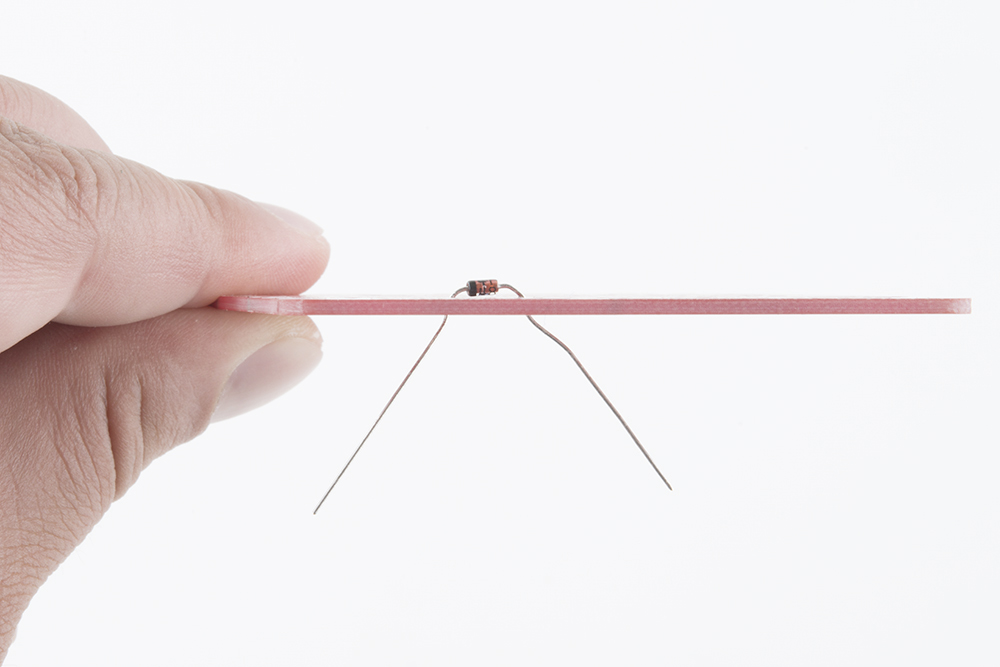
The diode gets mounted on the top the the PCB, the side with the silkscreen outline. Bend the leads so they fit through the holes, and push them through until the body sits on top of the PCB. You can bend the legs outward slightly to hold the diode while you work.
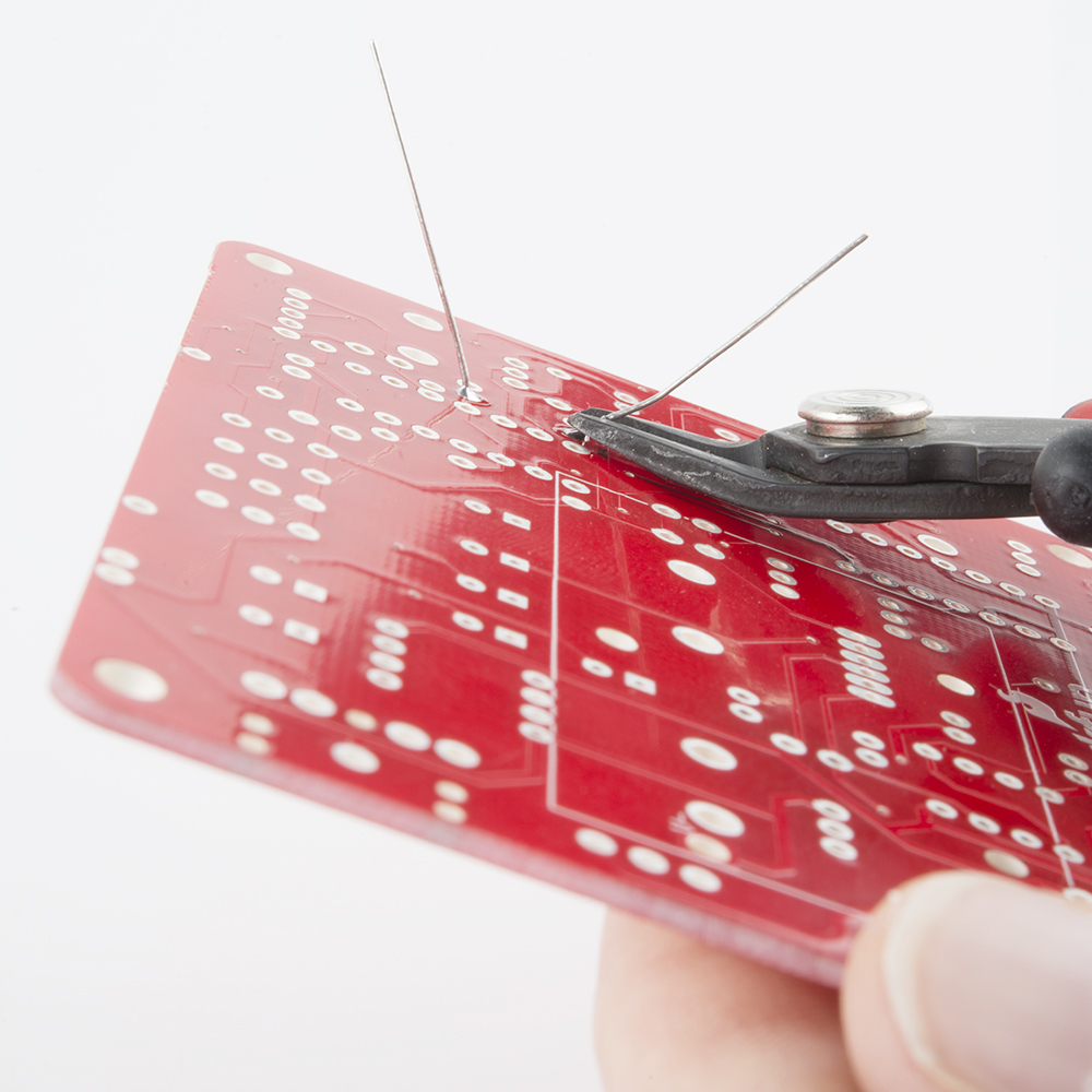
Turn the board over, solder the diode in place, then trim the excess leads near the fillet.
Install the other diode next to it. Again, it should be inserted with the stripes on both the body and PCB aligned, facing the same direction as the first diode.
After both silicon diodes are in place, let's install the Schottky diode. (Okay, it's a tiny bit larger than the resistors, but not so large that it will interfere with later steps).
It's a black cylinder with a gray or white stripe on one end. It goes here:
Like the silicon diodes, it's polarized. Match the stripe on the body with the stripe on the PCB. Solder it in, and trim the excess leads.
With all the diodes installed, your PCB should look like this:

Before proceeding, take a moment to verify that you have the stripes on the diodes oriented correctly.
Lather, Rinse, Repeat
The pattern we've established here (insert, solder, trim) will be repeated for each of the other components on the PCB.
Electronic Assembly II - Resistors
Resistors are not polarized - they can be installed in either orientation. We'll install the resistors in order of increasing resistance value. For each resistor value, we'll insert, solder and trim the excess leads just as you did with the diodes.
The resistor values are indicated by the colored stripes on the resistor body. We'll note the color codes in the photo captions below, but if you'd like a more thorough explanation of how the codes work, you can find that in our Resistor Markings Tutorial.
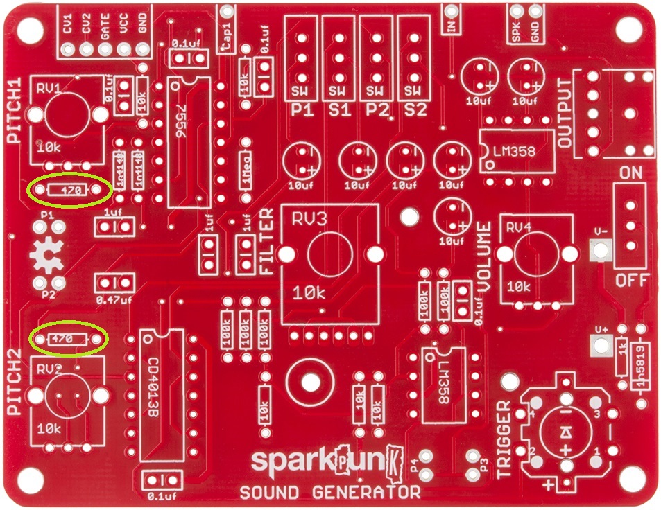
470 Ω
The lowest value resistors are the two 470 Ω resistors. They are located near the left edge of the PCB, as seen below:
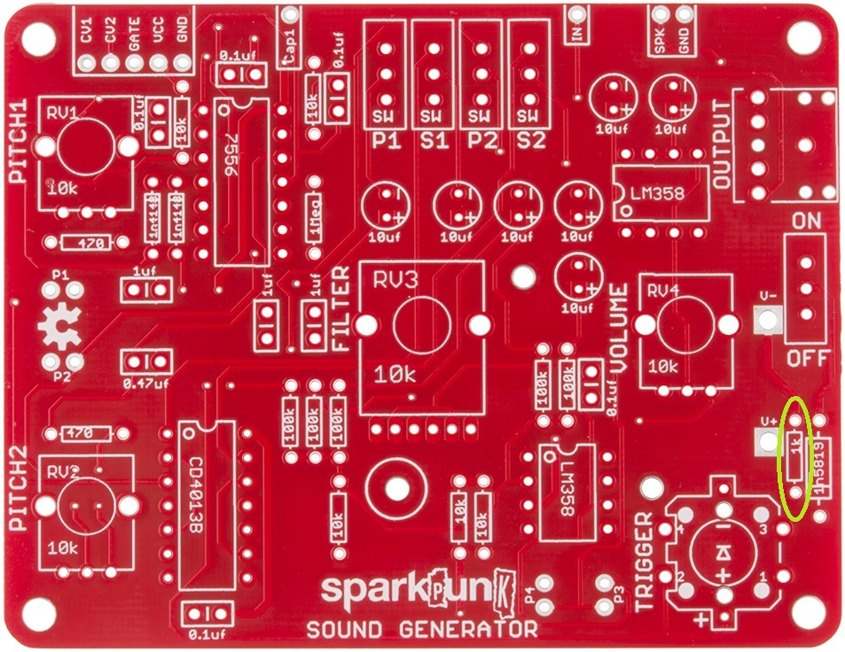
1K Ω
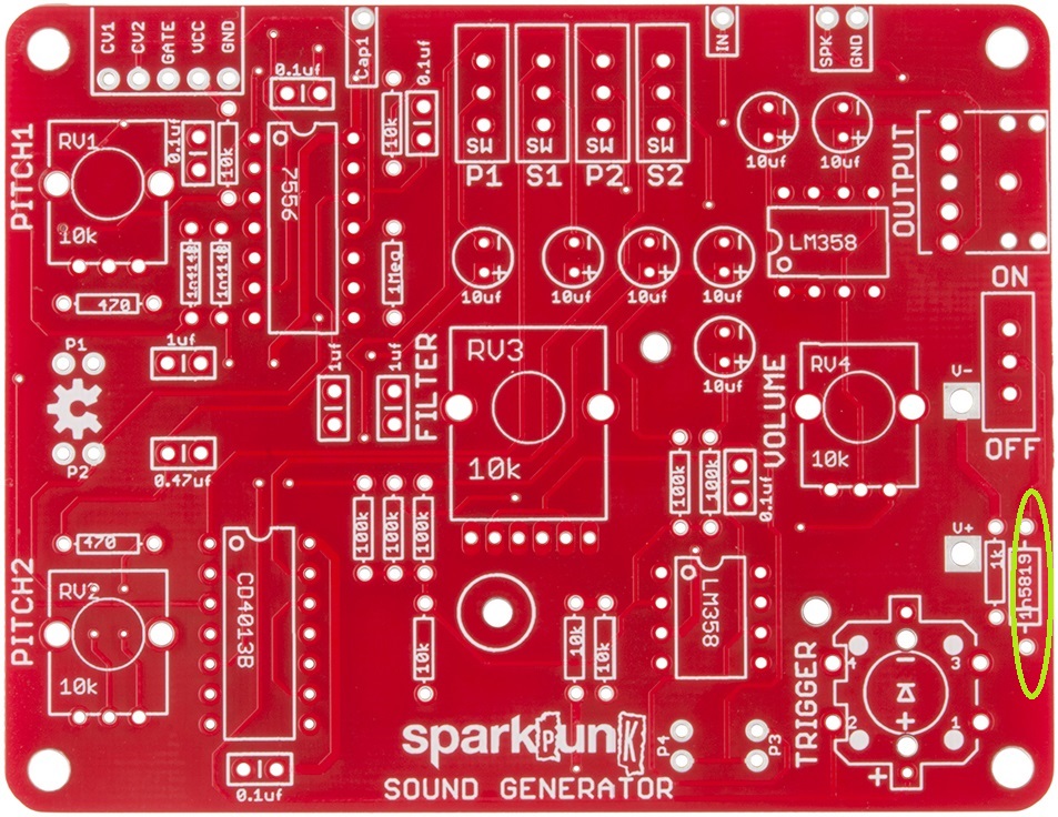
After the 470's is the 1k Ω resistor. It's located near the right edge of the board:
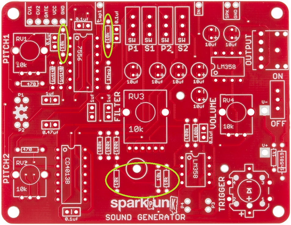
10K Ω
Next up are the 10K resistors. There are five of them, shown here:
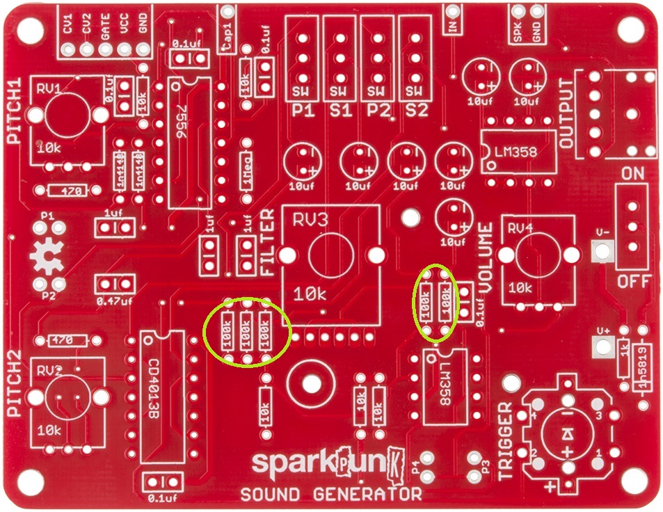
100K Ω
There are also five 100k resistors. They are installed near the middle of the PCB:
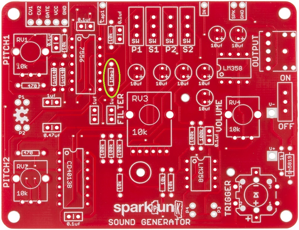
1 MΩ
Finally comes the 1 Mega-Ohm resistor. It goes here:
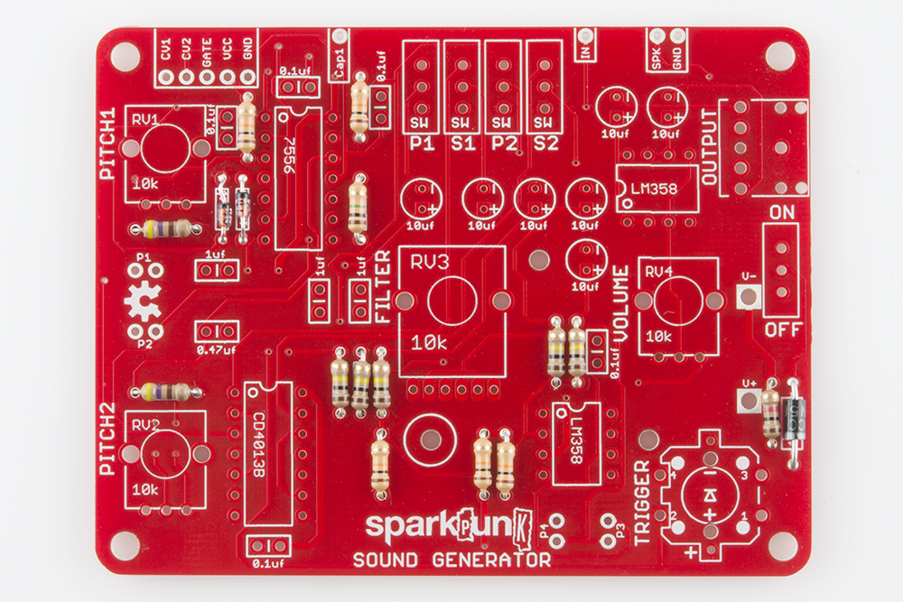
At this point, all of the diodes and resistors have been installed. Your board should look like this:
Electronic Assembly III - Capacitors and ICs
Capacitors
The next tallest components are the ceramic capacitors - they're usually little orange/yellow blobs with two leads.
Like the resistors, the ceramic caps are not polarized - they can be installed facing either direction.
The values are printed on the side of the caps, but in very tiny print - in some cases, it might be so small as to be nearly invisible. A magnifying glass can help, or you can figure out which is which by counting the number of each.
1µF Ceramic Capacitors
There are three 1µF caps, which are marked 105. They are installed here:
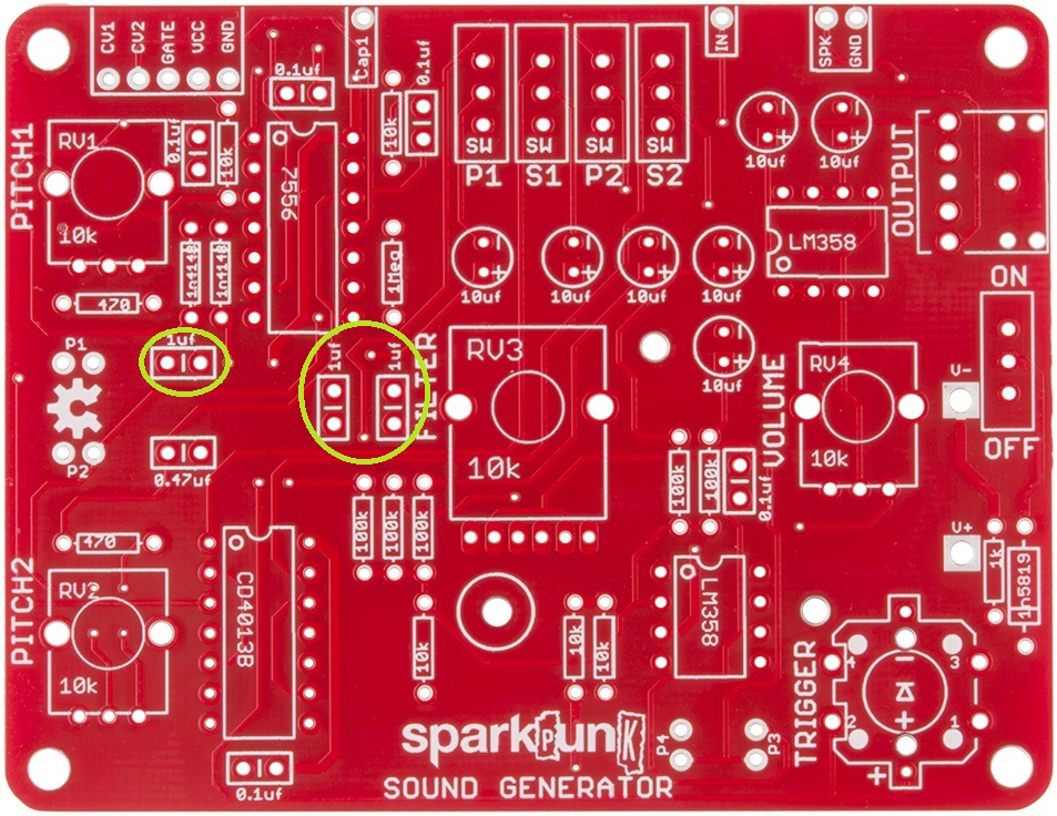
0.1µF Ceramic Capacitors1µF
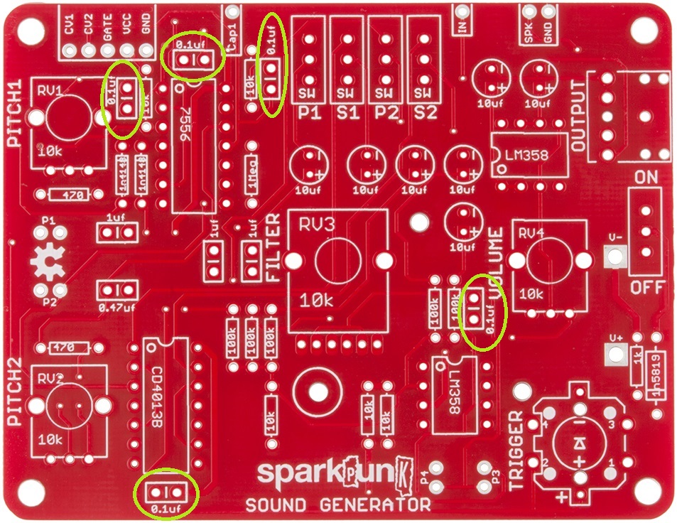
There are five 0.1µF caps. They are labeled 104, and should be located as follows:
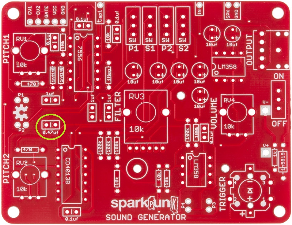
0.47µF Ceramic Capacitors
There is one 0.47 µF cap. It's marked 474, and it is located here:
Integrated Circuits
At this point, we're going to take a quick detour from the capacitors and put in the integrated circuits, because they're a little shorter than the electrolytic caps.
There are four integrated circuit (IC) chips on the SparkPunk. The ICs are polarized, usually marked with a notch at one end of the chip (if there's no notch, there's a dot or divot near one corner). Again, the PCB is marked to match the component.
When soldering in the chips, it can be useful to start by soldering down legs that are across from each other diagonally, to hold the chip in place while you solder the other legs.
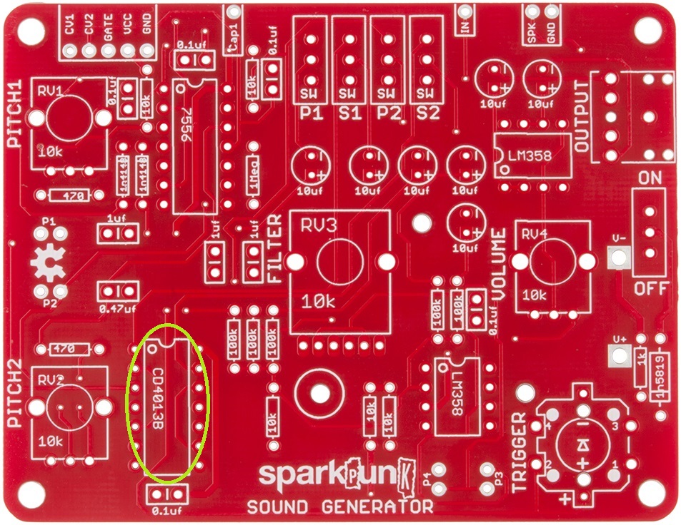
The ICM7556 and CD4013B are both 14-pin packages - take care to put each in the correct location.
Let's work from left to right, installing the chips.
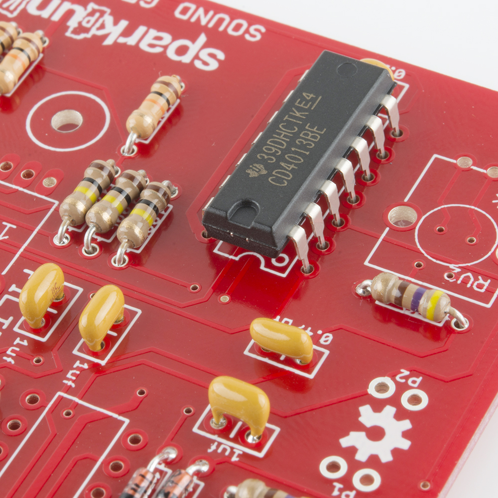
First is the CD4013B, in the lower left corner:
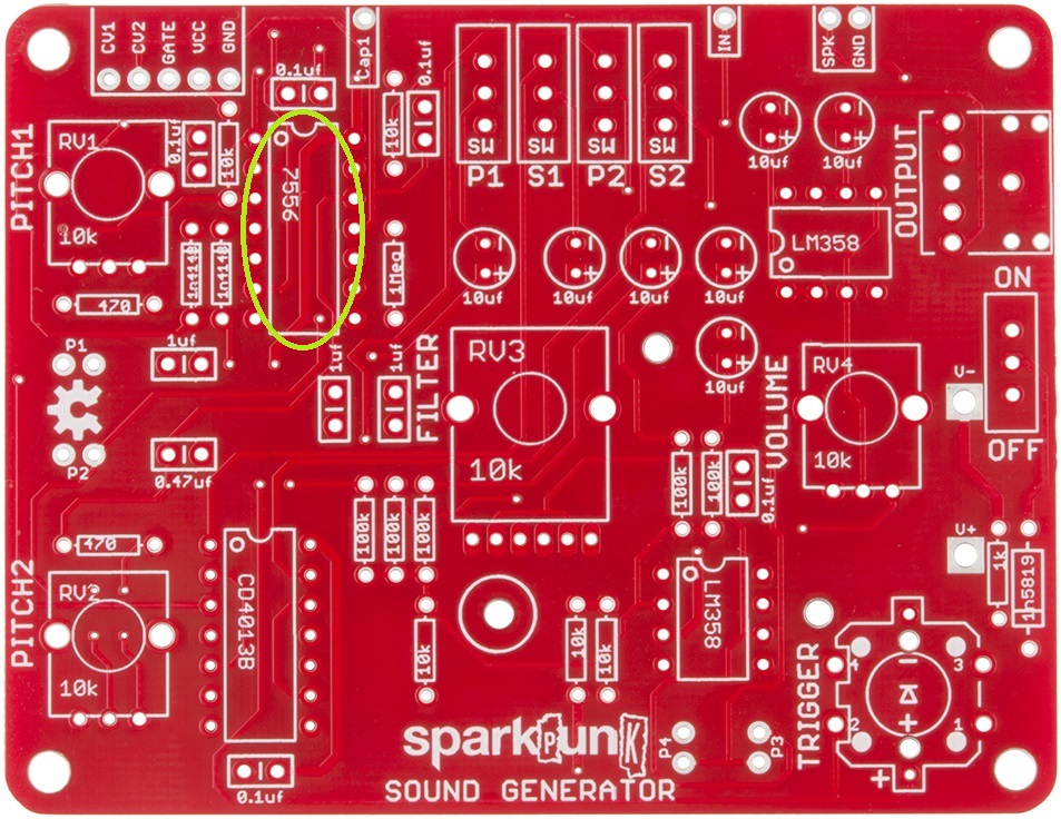
Following that is the ICM7556:
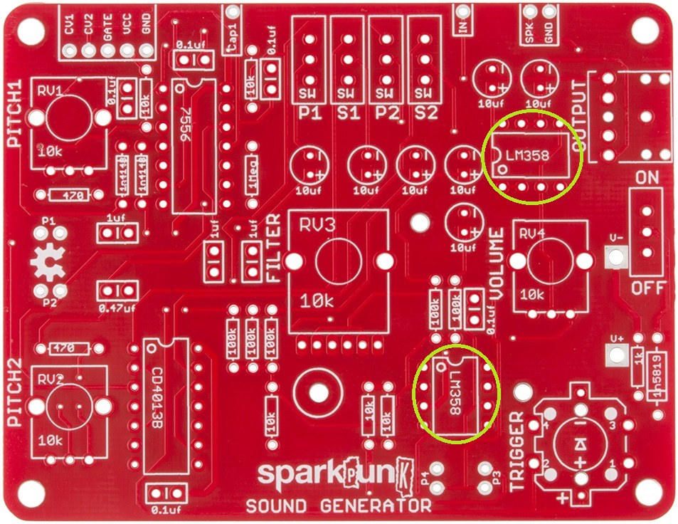
And Rounding up the ICs, lets put in the two LM358's:
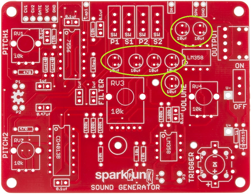
Electrolytic Caps
Electrolytic Capacitors are the small cylinders that look like tiny soda cans. They are polarized, having a positive and a negative lead. The positive lead is usually longer than the negative, and the negative side is usually marked on the body of the capacitor itself. The pads on the PCB are marked with both "+" and "-" symbols - the longer lead will go through the hole with the +. On this board, they all go in the same orientation, with the negative leg towards the top of the board.
Check Your Progress
At this point, all of the shorter electronic components have been installed. Your board should now look like this:
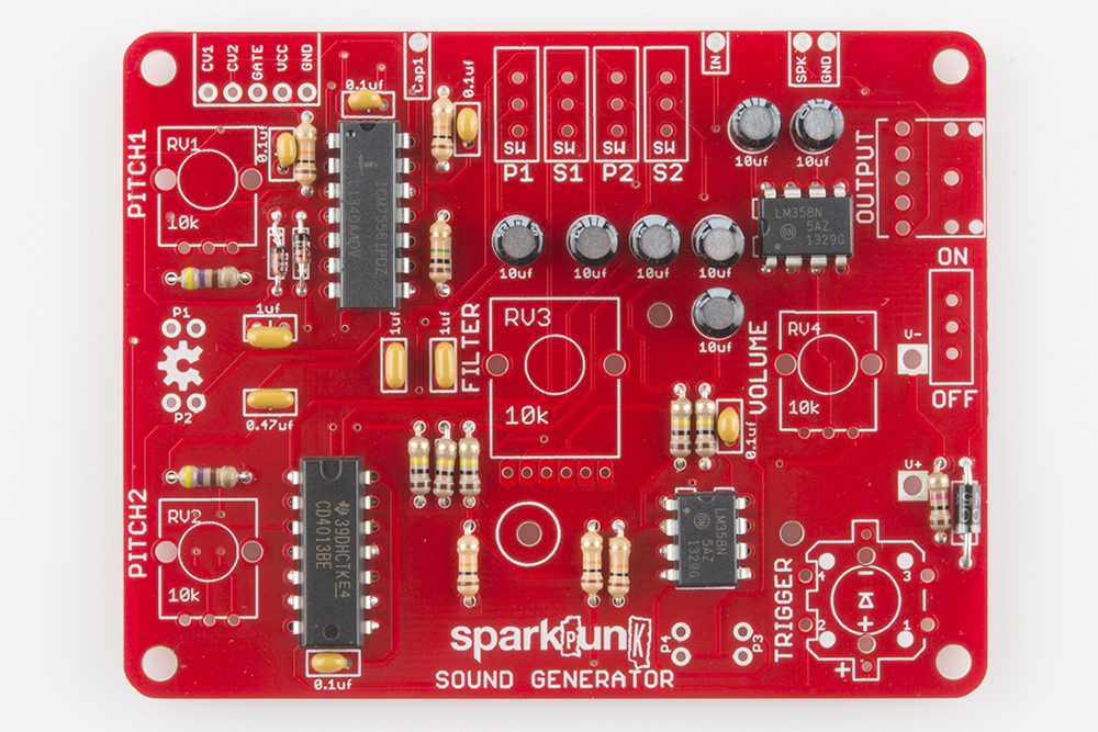
We're almost there - there are just a few more components to install.
Mechanical Assembly
At this point we have installed all of the electronic components, and it's time to move on to the electromechanical components.
Headphone Jack
The shortest electromechanical component is the headphone jack, in the upper right corner:
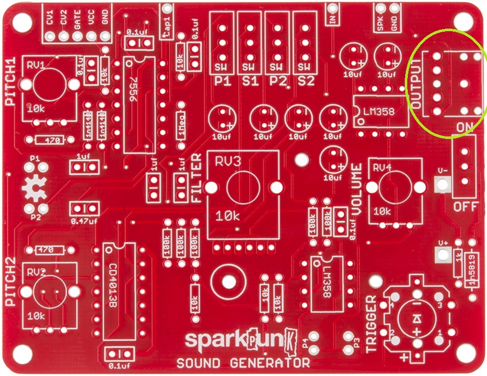
The headphone jack is placed so that the headphone socket points off the right side of the board. It also has small plastic feet that fit into holes on the PCB to help keep it in place. Be sure to solder all five metal legs down.
Switches
There are five small slide switches in the kit.
We'll save one of them for the very end, so it won't get in the way when we put in the battery box.
The first four are all located near the center of the top edge of the PCB:

The slide switches are not polarized.
Pushbutton
After the slide switches, we put in the pushbutton:
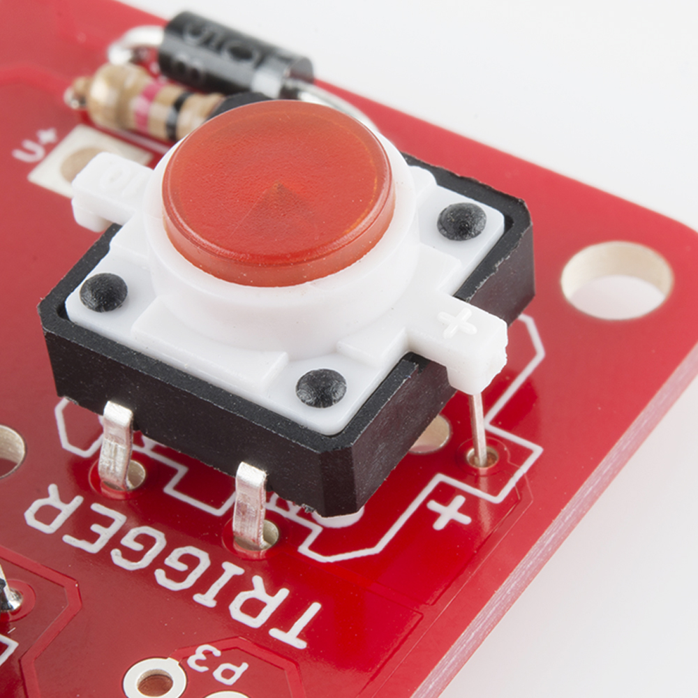
The pushbutton contains an LED, which is polarized. Take care to identify the proper orientation - there is a small "+" on one of the white plastic tabs, which lines up with the "+" on the PCB.
Potentiometers
The potentiometers are not polarized, but they'll only fit on the board one way.
It takes some care to get them onto the board. Start by lining up the smaller electrical legs, then push the two large tabs into the holes. If the leads or tabs have been bent in transit, they will need to be straightened out to fit the PCB. The tabs are a tight fit - gently rocking the pot from side to side can help. When inserted correctly, the back of the pot will sit flush on the top of the PCB.
When you solder them in, first solder down the tabs for stability, taking care that the pot stays flat on the board. Then solder the other connections.
We'll start with the three single-gang pots.
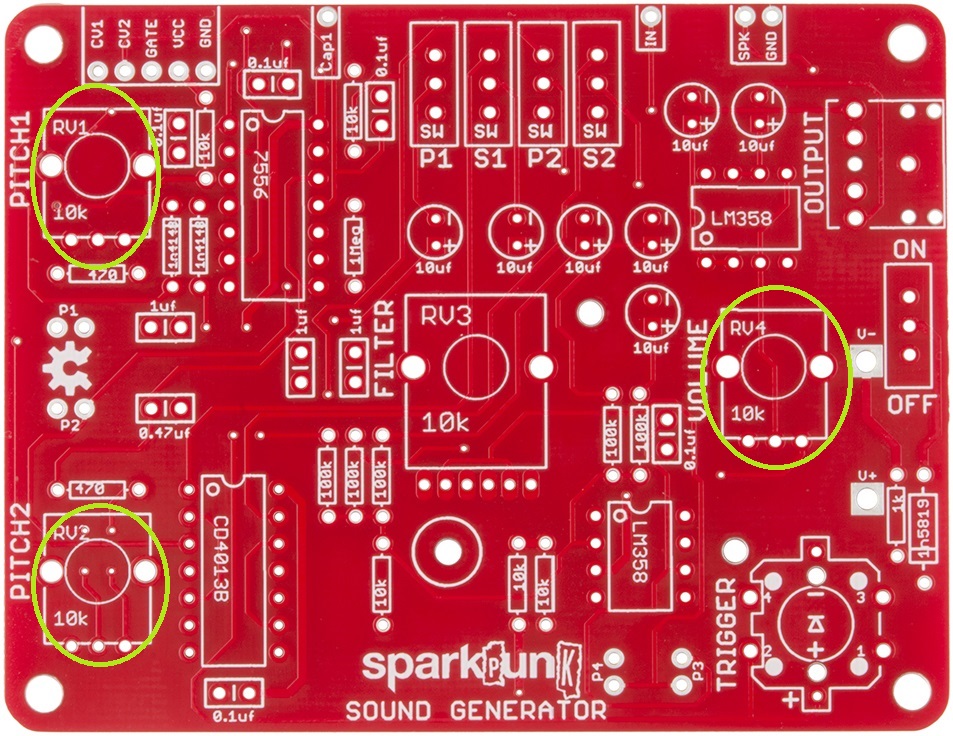
Next comes the dual-ganged pot, which has 6 legs. It goes in just like the smaller pots - align the smaller legs with the holes first, then push the tabs through the board.

Doublecheck your work
We're in the home stretch!
Before moving on, take a few moments to check your work this far. In particular, there are two things to watch out for.
- Verify that all of the polarized components have been installed correctly.
- Carefully inspect your solder work on the back of the board, checking for shorts and cold joints.
We're going to cover them with the battery holder in the next step, which makes it hard to see or fix any problems.
Battery box
When you're confident in your solder work, we move to the battery box. It goes on the back of the PCB:
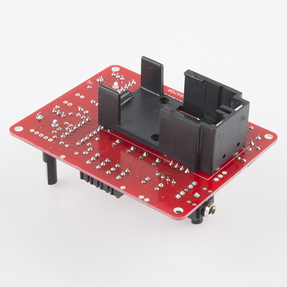
There are a small bolt and nut in the kit, which we'll use to secure the box while you solder. Put the leads through the holes and then secure the box with the bolt. Insert the screw from inside the battery compartment, with the nut on top of the board.
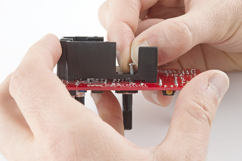
It gets soldered to the front of the PCB.
One More Switch
Finally comes the power switch, at the right edge of the PCB:
Assembly Complete
This should wrap up all of the soldering work. Take a moment to admire and double check your work. In particular, re-check the orientation of the polarized components - the diodes, ICs, electrolytic capacitors and pushbutton.
Your board should look like this:
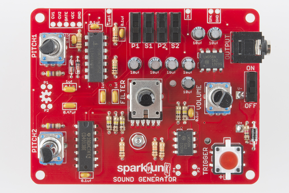
The only remaining part should be the 9 Volt battery. We'll install it and start testing the board on the next page.
Testing
With the assembly complete, we'll move on to testing your new SparkPunk. We will test it in a couple of stages.
You'll notice that as the board got assembled, a lot of the text and legends in the silkscreen got covered up by the components. The remaining text explains the function of the nearby controls. We'll denote those labels using text in boxes, like this.
Initial Testing
The first test is just a smoke test.
Install the battery in the battery compartment. There are a small "+" and "-" embossed in the box that will match the corresponding marks on the battery. The battery should slide into the holder, and be held in place by the tab at the back end. If it doesn't fit easily, make sure that you've got it aligned properly.
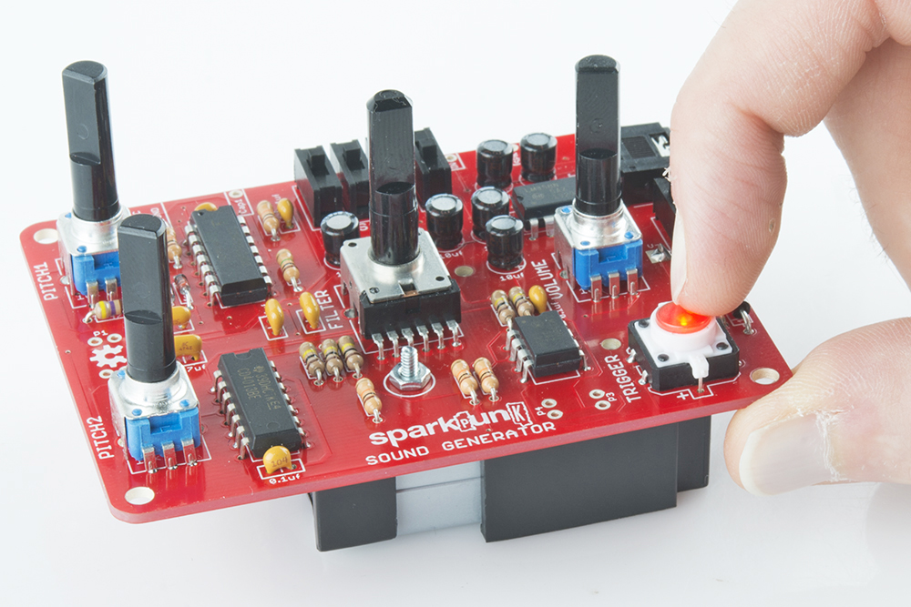
Turn the power switch on, then press the TRIGGER button. The button should light up while you are pressing it. If it doesn't light, check the troubleshooting suggestions below.
Sound Testing
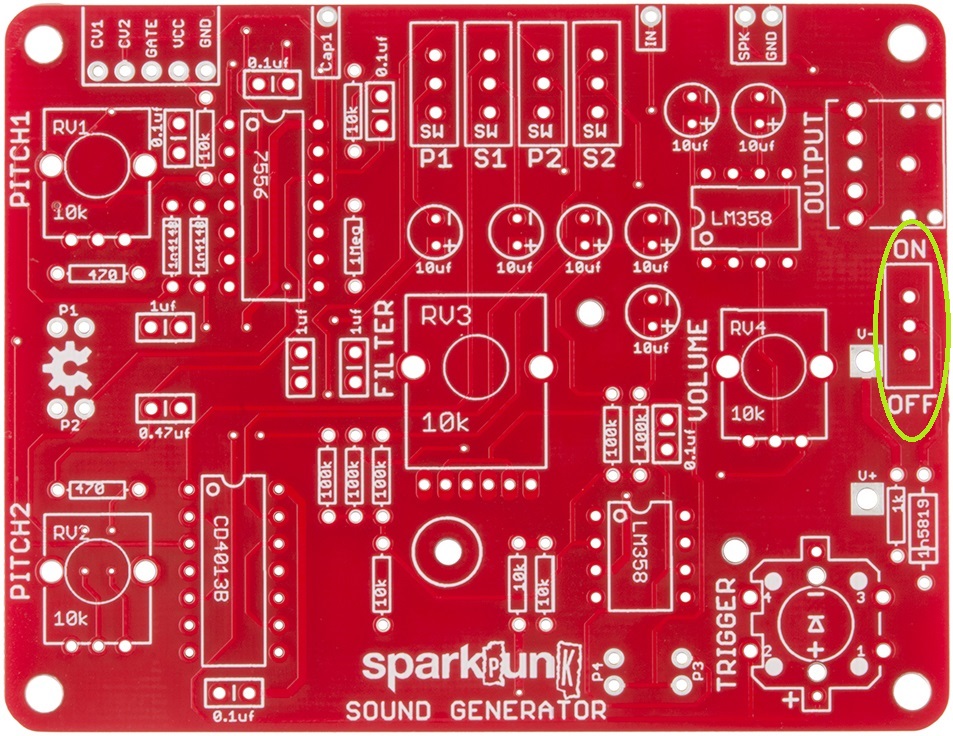
Once the button is working, we can move on to checking the sound output. To configure the test, we'll need to set all of the controls. Moving from left to right across the unit, configure the controls as follows:
- Turn
PITCH1andPITCH2pots fully counterclockwise - Turn on the
P1switch by sliding it upward - Turn off the
S1,P2andS2switches by sliding them downward - Put the
FILTERpot at the center of it's rotation - Turn the
VOLUMEpot all the way down (counterclockwise) - Connect headphones to the
OUTPUTjack - Turn the unit
ON
Now press and hold the TRIGGER button, while slowly turning up the VOLUME control. You should hear a tone that gets louder as the volume control turns. If so, congratulations! But if not, don't worry - just skip ahead to the troubleshooting section.
More Detailed Testing
Now we'll check that all of the controls are are functional.
Turning the PITCH1 potentiometer should change the frequency that you are hearing.
Turn the filter knob back and forth. The pitch will stay the same, but the tone will vary. The filter has a similar effect to a wah-wah pedal for electric guitar. You'll probably find that the effect is more audible for the upper half (12 o'clock to 5 o'clock) of the pot rotation.
Now turn off P1 and turn on P2. The PITCH2 control should change the frequency.
Next, work your way across the P1, S1, P2 and S2 switches, trying each in turn. Each should produce a different sound. You can also turn on more than one at a time to produce various combinations.
All Done?
When all of the controls check out, you have a functional SparkPunk!
But, it doesn't end there. In the next section, we'll explain in higher detail exactly what all these controls do and how the underlying circuit works.
You can also modify and extend the SparkPunk - it's a great platform to start modifying or circuit bending. We describe a few mods you can start with in the Modifications section.
Troubleshooting
The first step in general troubleshooting is to doublecheck your work.
- Check that the polarized components are in correctly. These include:
- The diodes
- The pushbutton
- Each IC chip
- The electrolytic capacitiors
- The battery
- Make sure that all of the solder connections have flowed correctly, with just the right amount of solder - not too little or too much.
- Verify you have your headphones or speaker connected.
- Make sure that the battery isn't dead, and the power switch is turned on. You can do so with a multimeter.
If things still aren't working, try contacting Sparkfun's friendly customer support team.
How It Works
How To Play The SparkPunk
The SparkPunk is a very simple synthesizer, using the common arrangement of oscillators that feed a filter.
The basic recipe for playing it is to press the button, and operate the controls. Listen to the results, and adjust to taste. Explore and have fun. Some people are drawn to mellow, soothing sounds, while others prefer clangourous tones. With all of the controls, you should be able to explore both ends of the spectrum.
In order to apply the SparkPunk more meaningfully, it helps to understand what's inside, and how the switches and pots control it.
Block Diagram

The block diagram above illustrates the major functional blocks of the SparkPunk. Following things from left to right, we first see the trigger pushbutton. It is connected to the oscillators, which are allowed to run when the button is pressed - otherwise they are silent. The output of each oscillator is translated an octave lower by the sub-octave generators. The oscillator waveforms and suboctaves can be selected using the switches, which mix them together, before reaching the bandpass filter. Finally, the signal goes to the volume control and output buffer amplifiers, which allow the SparkPunk to drive small speakers or headphones.
We'll cover how each of these pieces works in more detail in the next few sections.
Theory of Operation
Oscillators
The heart of the SparkPunk is the 7556 dual timer IC. The 7556 is a CMOS replacement for the 555.
A quick digression into the history of this part: the 555 might be considered one of the classic integrated circuits - so useful and versatile that Forrest M Mims wrote a whole booklet full of 555 circuits. The 555 has a close relative in the 556, which is simply two 555's in the same package. However, the 555 and 556 draw a lot of current (leading to shorter battery life), and can introduce noise into the power supply. The 7555 and 7556 are CMOS replacements for the older chips, which draw substantially less current. Thus 555 x 2 = 556. 556 + CMOS = 7556.
The SparkPunk uses the the 7556 in a stable (free-running) mode. The circuit is from figure figure 2A of the 7555 datasheet. The resistor R has been replaced with a potentiometer series with a 470 Ohm resistor, to limit the maximum frequency when the pot is at minimum resistance.
The frequency is calculated using the formula f = 1/(1.4RC). The 7556 has two timer circuits inside, and the SparkPunk uses both, configured identically, except for the capacitor values - the first channel produces lower pitches than the second, as shown in the following table.
| Channel | Cap Value | Maximum R (Pot at CCW) | Minimum R (Pot at CW) | Minimum Frequency | Maximum Frequency |
| 1 | 1 uF | 470 | 10470 | 68 | 1519 |
| 2 | 0.47 uF | 470 | 10470 | 145 | 3233 |
The actual frequencies will vary due to component tolerances.
The circuit also makes use of the reset and control voltage inputs on the 7556.
The chip is held in reset until the pushbutton in pressed, or a voltage is present on the GATE input of the expansion port. These two voltages are combined with the diode OR gate formed by D1, D2 and R5.
The 7556 also has control voltage inputs, which are connected to the expansion port. We'll cover the expansion port in more detail on the modifications page.
Sub-Octave
The sub octave circuit is created using a T-type (toggle) flip-flop. The pulse waves from the oscillators are tied to the clock input of the CD4013 flip-flop. On every rising edge from the 7556, the flip-flop changes state. You can see this on the oscilloscope below:

Each rising edge on the top waveform causes the bottom waveform to change state, while falling edges on the top are ignored. This results in a second wave with one half the frequency of the input. This behavior is also known as "clock division."
In musical terms, halving a frequency is equivalent to dropping one octave. This yields a wave that can add richness to the original, without adding very many components - one IC is used to generate both sub-octaves. Because it tracks the input signal, it also stays in tune as the oscillator pitch changes.
Mixer
With two oscillators and two suboctaves, we have a total of four tone sources. The sources are combined using an inverting op-amp summing stage.
The switches marked P1, P2, S1, and S2 connect the signal to the summing bus, allowing for 16 different combinations of the oscillators and suboctaves.
Since the 7556 and flip-flop are logic sources, each input to the mixer is swinging between the supply rails - square waves that jump between 0V and 9V. If we were to try to combine them directly, we could wind up with a total voltage of 36V. The opamp is only capable of swinging to slightly less than the rails, so each input is attenuated by a factor of 1/10, leaving the result in the 3.6V range.
Filter
The filter is an active bridged-T topology. A passive bridged-T is a simple notch filter.
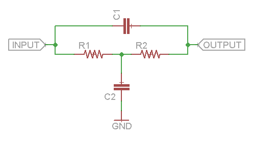
By placing that filter in the feedback loop of an op-amp, we can invert the frequency response, turning the notch into a peak.
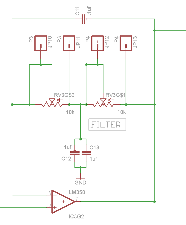
This filter topology was selected for several reasons. It doesn't take too many components, and it allows the filter to be tuned with a pair of equal value resistors, in this case a dual-gang potentiometer. Finally, the peak amplitude doesn't change as a function of frequency, which sounds cool when you turn the knob!
There is a spice file containing a number of other filter topologies in the GitHub repository, showing how some alternate filters compare.
Output Stage
The output stage is a volume control, followed by a pair of op-amp buffers, AC coupled to the output pins via the electrolytic caps C14 and C15. When stereo headphones are connected, each ear is driven by a separate amplifier. There are also connection points for an optional loudspeaker.
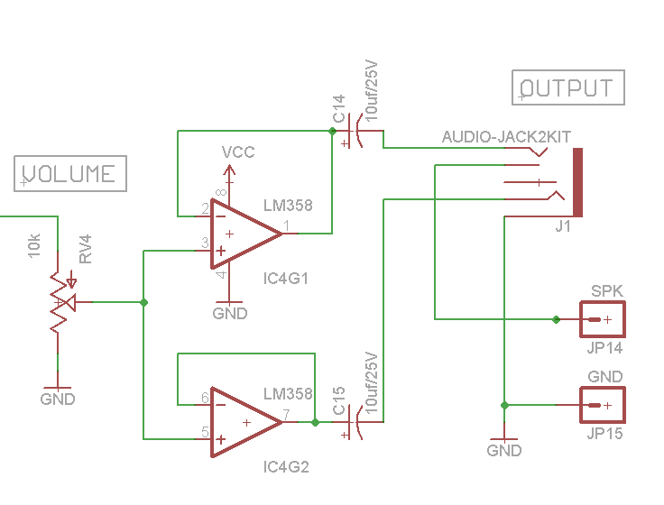
The output jack has a switching feature - it provides a default connection when nothing is plugged in, that is overridden when something is connected. On the SparkPunk, the speaker terminals are the default connection, which is broken when headphones are inserted. This means plugging in headphones silences the speaker.
Design files
The schematic and PCB artwork are in the GitHub repository.
There are also LTSpice circuit simulation files for the unit as a whole, with some of the intermediate portions in separate simulations.
Modding the SparkPunk
With this understanding of the guts of the SparkPunk, let's explore how we can modify and customize the kit.
Modifications
The SparkPunk was designed with the idea that it can be customized, modified and extended. Your circuit bending is welcome here.
Cosmetics
Customize your SparkPunk by adding the knobs of your choice.
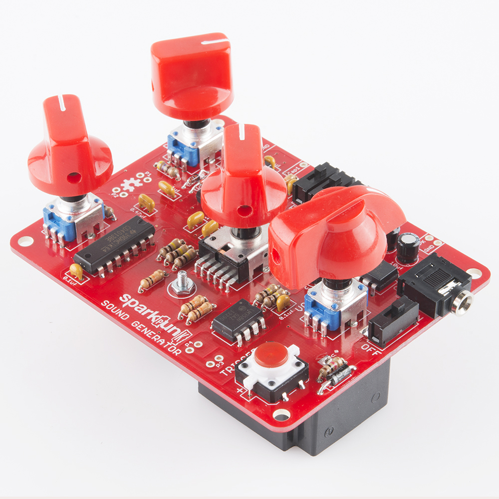
The author likes using the small red stove-type knobs for the pitch and filter controls, and a red chickenhead for the volume control. Of course, the Goes To Eleven knobs have their benefits, as well.
Once you've got knobs, you can loop rubber bands around the knobs, so you can adjust multiple parameters simultaneously. You can also cross the rubber band over in a figure-8, so that turning one knob up turns another down.
Without Adding Components
The ceramic capacitors that set the frequency of the oscillators are very temperature dependent. These are the two caps between the pitch potentiometers, near the OSHW gear logo. By simply touching them with a warm fingertip, you can cause the pitch to drift. If you start with the oscillators in tune with each other, touching one of those caps will cause them to drift, resulting in a pulsating beat-frequency effect.
As inspired by the Handmade Electronic Music book, you can explore the back of the circuit board with a damp fingertip. You'll find that some locations cause notes to spontaneously trigger, pitches to bend, or other random misbehavior.
Adding Electronic Components
External Speaker
You can solder a small speaker (such as this or this) between the terminals marked "SPK" and "GND."

As we mentioned in the How It Works section, plugging in headphones will disable the speaker, so you can enjoy your SparkPunk without disturbing others.
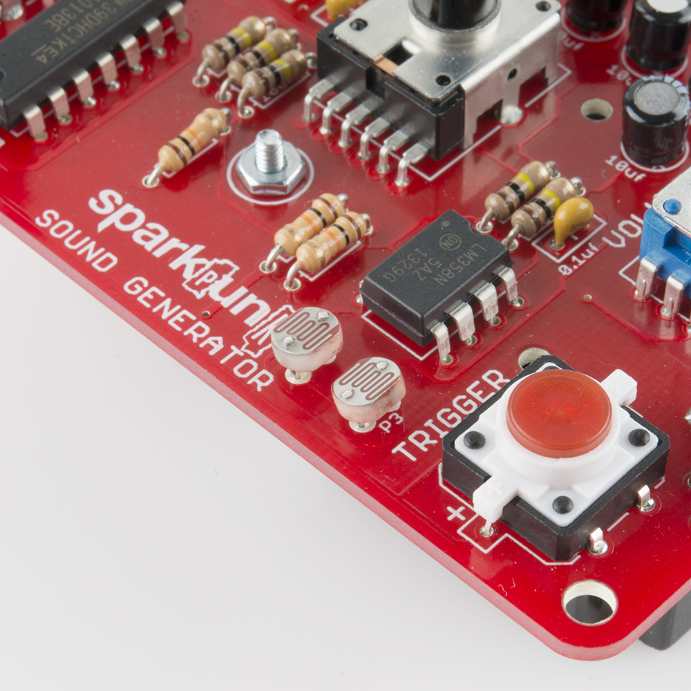
Photocells
There are positions on the PCB for adding photocells to the SparkPunk. Photocells are resistors that change value depending on exposure to light. In the dark they have a high value, which drops as they are illuminated. The result is that you can control the SparkPunk without touching it.
Positions P1 and P2, between the pitch potentiometers, control pitch 1 and pitch 2, respectively.
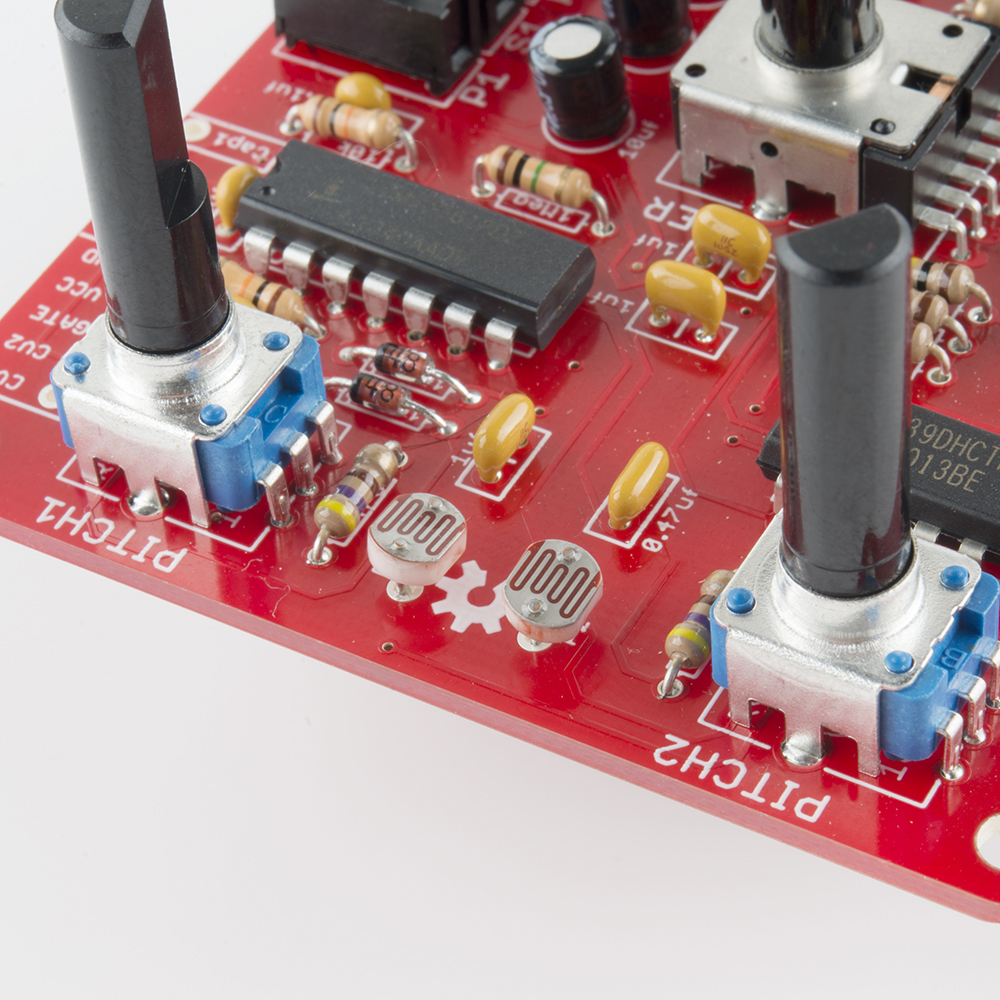
Populate P3 and P4 (near the trigger button) to make the filter cutoff frequency light-sensitive.
The photocells are in parallel with the potentiometers. The pots and photocells interact - you can experiment with how the pot rotation influences the light response of the cells.
External Input
The pad IN can be used to route external signals through the SparkPunk filter. They will be mixed with the output from the pitch and sub-octave stages.
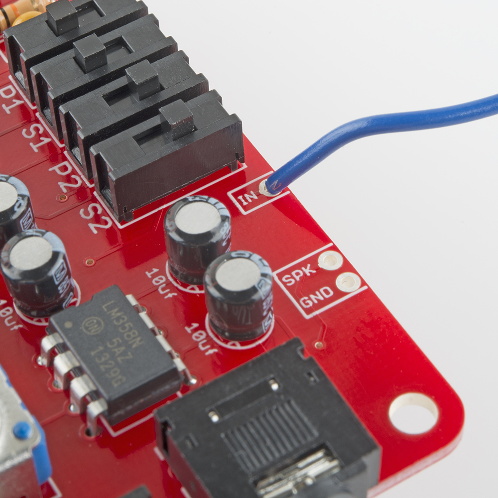
For instance, this could be used with the Gram Piano. Desolder the speaker from the Gram Piano, and run a wire from the Gram Piano's speaker "+" terminal to the IN pad on the SparkPunk. Now you can effect the piano output using the SparkPunk filter.
Cross Modulation
Connect CAP1 to CV2, then turn on P2 and/or S2. They will react in interesting ways as you adjust PITCH1 and PITCH2.
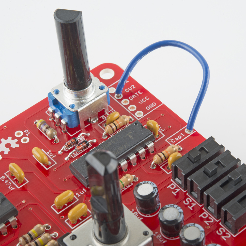
This is a simple form of frequency modulation - it modulates the frequency of the second oscillator using a voltage from the first. The results are a simple form of heterodyning, commonly called "ring modulation" in music effects terminology.
Swapping Components
There are several places where changing a component or two has a large influence over the resulting sound.
Oscillators
The frequency range of each oscillator is set by a capacitor. C3 sets the range for the first oscillator, C4 for the second, respectively 1uf and 0.47uf. They are located between the pitch pots. You can change the range of the oscillators by substituting different caps. Larger caps will take longer to change, thereby lowering the frequency.
If you simply want to be able to tune lower, solder a second cap of the same value (1uf for C3, 0.47 for C4) in parallel with the originals. This will drop everything an octave.
Filter
By changing the capacitors, the filter can be altered a couple of different ways.
The capacitors were originally selected ratiometrically. The parallel combination of C12 and C13 is 2uF, 20 times the 0.1uf of C11. The ratio here determines the width and amount of boost at the center of the peak. Changing the ratio of the caps will alter the value - one simple way to experiment with this is to remove C12, lowering the boost to about 15 dB, from the stock value of 20 dB.
If you keep the ratio the same, but change the values, you can change the center frequency.
You can evaluate and compare the differences by running the filter Spice simulations from the SparkPunk GitHub simulation folder. A decent analysis of bridged-T component parametrics can be found here.
External Interface Header - Room To Grow
You've probably noticed the 5-pin header near the upper-left corner. It's an analog expansion port allowing access to signals that control the 7556.
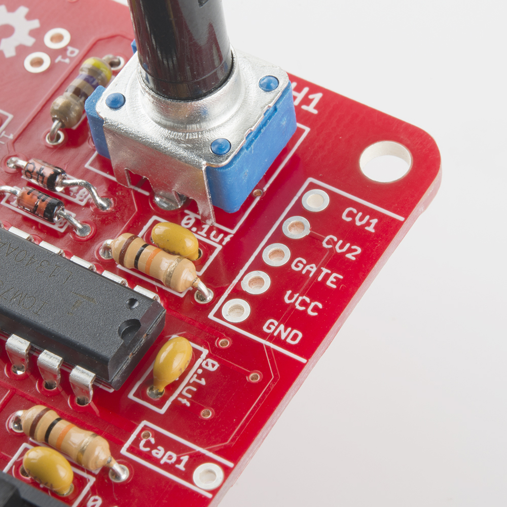
Each oscillator has a control voltage input, marked CV1 and CV2. By feeding a voltage into these pads you can adjust the oscillator frequency. If you're familiar with regular synthesizer control voltage inputs, these aren't what you're expecting. The range is somewhat small and inverted - a higher voltage will lead to a lower frequency. The useful range is roughly from 1/3 VCC to 2/3 VCC, or 3V to 6V. That range gives about an octave of frequency shift. Driving outside that range can cause the oscillator to glitch or stall - worth experimenting with if you like quirky sounds.
The GATE input starts the oscillators. Applying a positive voltage there allows the oscillators to run, just as pressing the trigger button does.
VCC and GND are the power rails of the SparkPunk, so you can power add-on circuitry from the 9V battery.
Experiment On Your Own
We've only scratched the surface here - there are many possible modifications for the SparkPunk!
The sky is the limit!
Resources and Going Further
Resources
- Design files for the SparkPunk can be found on GitHub
- The Github files include Spice simulations that run in LTSpice
- SFE Product Showcase
If you're interested in parts and kits that complement the SparkPunk, take a look at these:
- Red Stove Knob
- Black Stove Knob
- Red Chickenhead Knob
- Black Chickenhead Knob
- Small GTE Knob
- Medium GTE Knob
- Large GTE Knob
- Photocell
- Thin Speaker
- 0.5W Speaker
- Gram Piano
- Audio Amplifier Kit
Going Further
- The original Atari Punk can be found of page 26 of Morrest M. Mims' Timer, OpAmp & Optoelectronic Circuits & Projects
- Reed Ghazala is the father of circuit bending. His website has a nice introduction to bending.
- Nic Collins' Handmade Electronic Music book has more information on circuit bending, and a number of musical circuits you can build from scratch.