Digital Logic
 SFUptownMaker
Combinational Logic
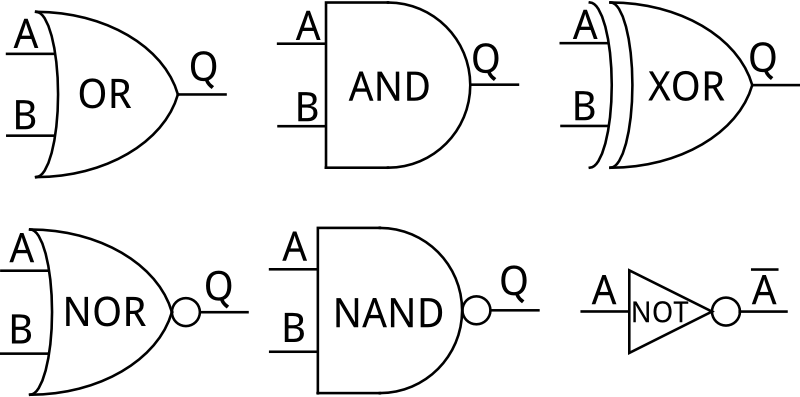
Combinational circuits are built of five basic logic gates:
- AND gate - output is 1 if BOTH inputs are 1
- OR gate - output is 1 if AT LEAST one input is 1
- XOR gate - output is 1 if ONLY one input is 1
- NAND gate - output is 1 if AT LEAST one input is 0
- NOR gate - output is 1 if BOTH inputs are 0
There is a sixth element in digital logic, the inverter (sometimes called a NOT gate). Inverters aren't truly gates, as they do not make any decisions. The output of an inverter is a 1 if the input is a 0, and vise versa.
A few things of note about the above image:
- Usually, the name of the gate is not printed; the symbol is assumed to be sufficient for identification.
- The A-B-Q type terminal notation is standard, although logic diagrams will usually omit them for signals which are not inputs or outputs to the system as a whole.
- Two input devices are standard, but you will occasionally see devices with more than two inputs. They will, however, only have one output.
Digital logic circuits are usually represented using these six symbols; inputs are on the left and outputs are to the right. While inputs can be connected together, outputs should never be connected to one another, only to other inputs. One output may be connected to multiple inputs, however.
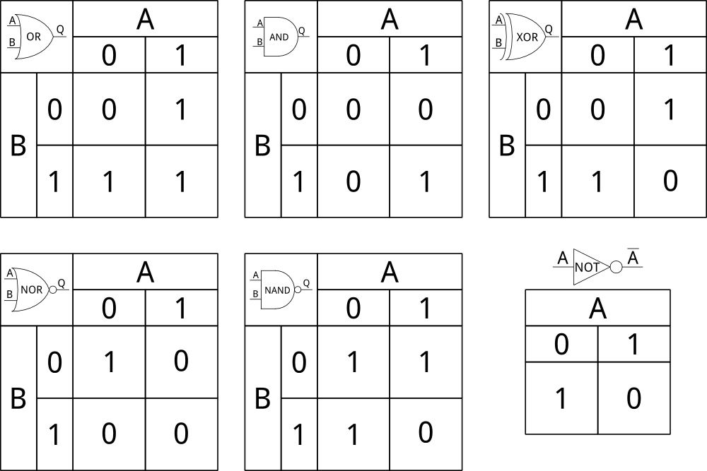
Truth Tables
The descriptions above are adequate to describe the functionality of single blocks, but there is a more useful tool available: the truth table. Truth tables are simple plots which explain the output of a circuit in terms of the possible inputs to that circuit. Here are truth tables describing the six main elements:
Truth tables can be expanded out to an arbitrary scale, with as many inputs and outputs as you can handle before your brain melts. Here's what a four-input circuit and truth table look like:

Written Boolean Logic
It is, of course, useful to be able to write in a simple mathematical format an equation representing a logical operation. To that end, there are mathematical symbols for the unique operations: AND, OR, XOR, and NOT.
- A AND B should be written as AB (or sometimes A • B)
- A OR B should be written as A + B
- A XOR B should be written as A ⊕ B
- NOT A should be written as A' or A
You'll note that there are two missing elements on that list: NAND and NOR. Typically, those are simply represented by complementing the appropriate representation:
- A NAND B is written as (AB)' , (A • B)' , or (AB)
- A NOR B is written as (A + B)' or (A + B)