SparkPunk Hookup Guide
 Byron J.
Mechanical Assembly
At this point we have installed all of the electronic components, and it's time to move on to the electromechanical components.
Headphone Jack
The shortest electromechanical component is the headphone jack, in the upper right corner:
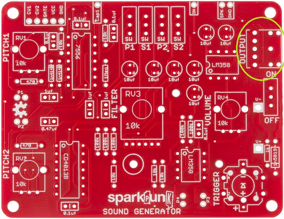
The headphone jack is placed so that the headphone socket points off the right side of the board. It also has small plastic feet that fit into holes on the PCB to help keep it in place. Be sure to solder all five metal legs down.
Switches
There are five small slide switches in the kit.
We'll save one of them for the very end, so it won't get in the way when we put in the battery box.
The first four are all located near the center of the top edge of the PCB:

The slide switches are not polarized.
Pushbutton
After the slide switches, we put in the pushbutton:
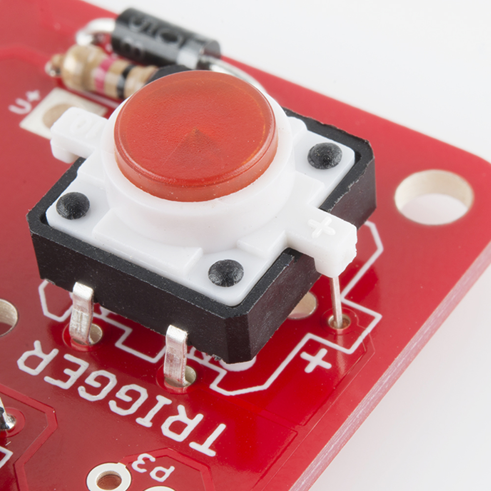
The pushbutton contains an LED, which is polarized. Take care to identify the proper orientation - there is a small "+" on one of the white plastic tabs, which lines up with the "+" on the PCB.
Potentiometers
The potentiometers are not polarized, but they'll only fit on the board one way.
It takes some care to get them onto the board. Start by lining up the smaller electrical legs, then push the two large tabs into the holes. If the leads or tabs have been bent in transit, they will need to be straightened out to fit the PCB. The tabs are a tight fit - gently rocking the pot from side to side can help. When inserted correctly, the back of the pot will sit flush on the top of the PCB.
When you solder them in, first solder down the tabs for stability, taking care that the pot stays flat on the board. Then solder the other connections.
We'll start with the three single-gang pots.
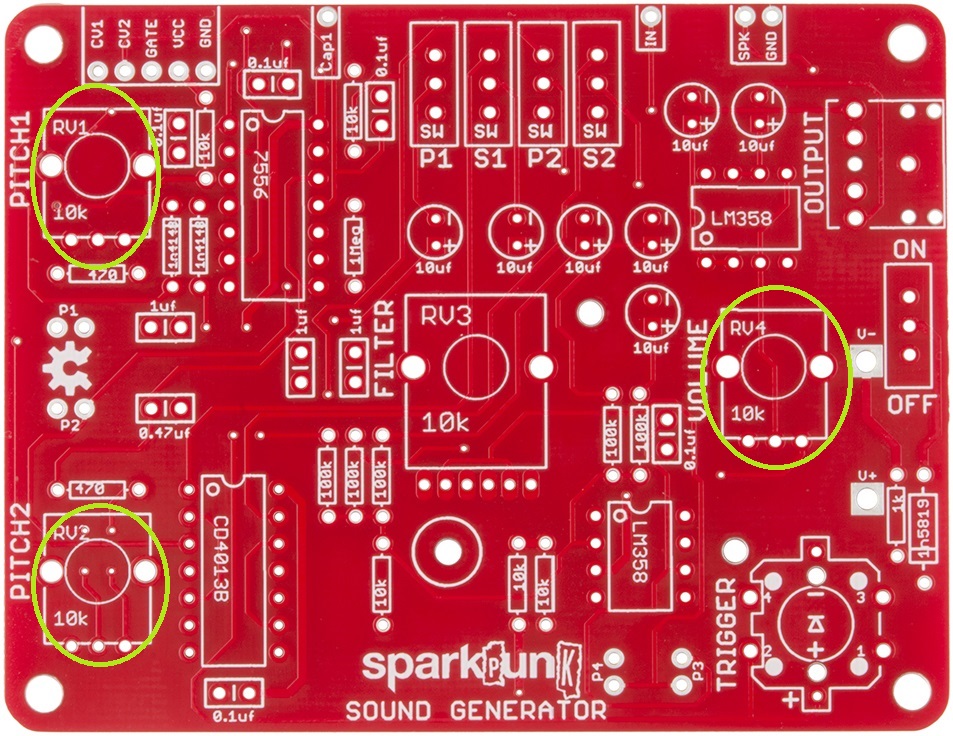
Next comes the dual-ganged pot, which has 6 legs. It goes in just like the smaller pots - align the smaller legs with the holes first, then push the tabs through the board.

Doublecheck your work
We're in the home stretch!
Before moving on, take a few moments to check your work this far. In particular, there are two things to watch out for.
- Verify that all of the polarized components have been installed correctly.
- Carefully inspect your solder work on the back of the board, checking for shorts and cold joints.
We're going to cover them with the battery holder in the next step, which makes it hard to see or fix any problems.
Battery box
When you're confident in your solder work, we move to the battery box. It goes on the back of the PCB:
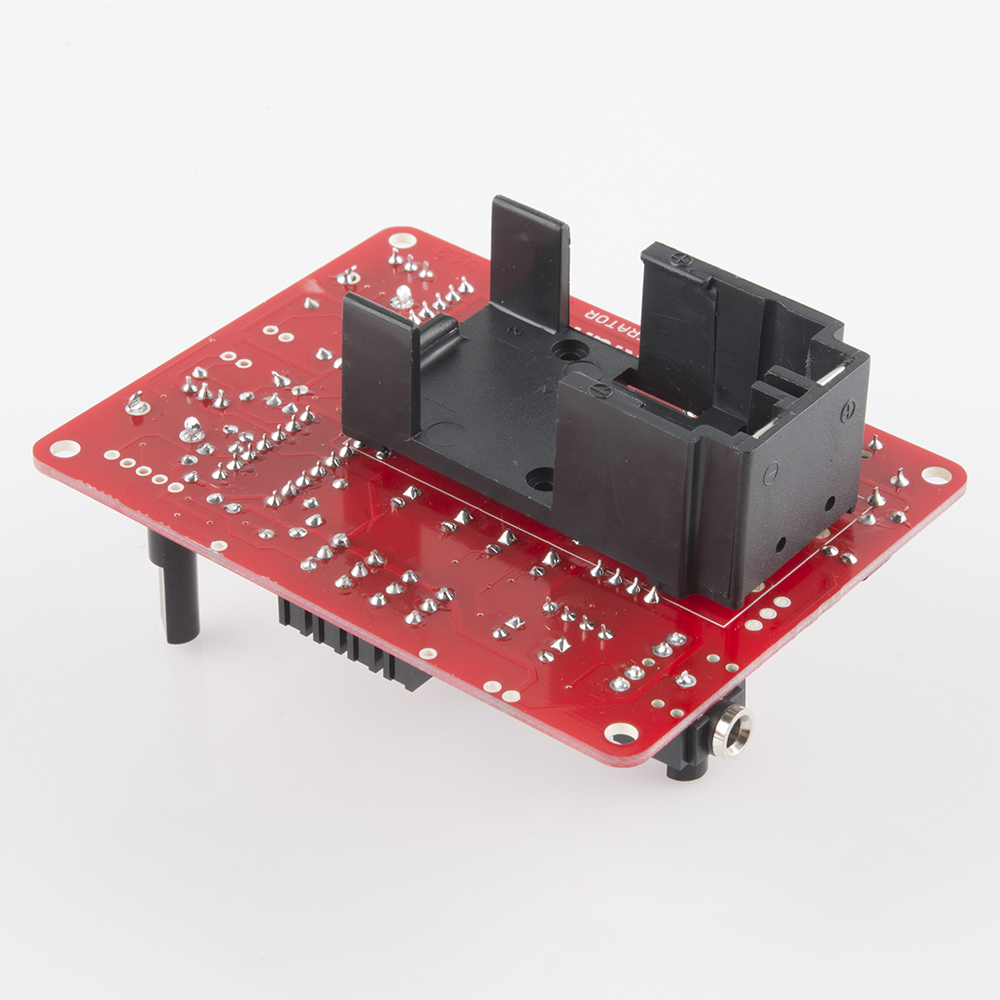
There are a small bolt and nut in the kit, which we'll use to secure the box while you solder. Put the leads through the holes and then secure the box with the bolt. Insert the screw from inside the battery compartment, with the nut on top of the board.
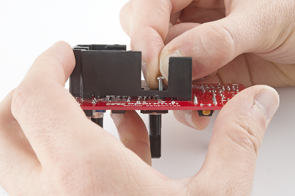
It gets soldered to the front of the PCB.
One More Switch
Finally comes the power switch, at the right edge of the PCB:
Assembly Complete
This should wrap up all of the soldering work. Take a moment to admire and double check your work. In particular, re-check the orientation of the polarized components - the diodes, ICs, electrolytic capacitors and pushbutton.
Your board should look like this:
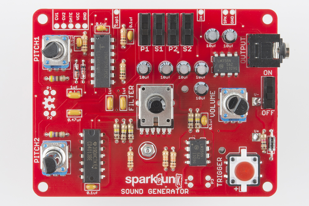
The only remaining part should be the 9 Volt battery. We'll install it and start testing the board on the next page.