SparkFun WiFi IR Blaster Hookup Guide
 jimblom,
  Englandsaurus
Programming the ESP8266
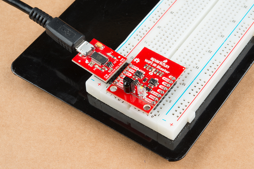
The WiFi IR Blaster's ESP8266 is designed to be programmed with a 3.3V FTDI Basic or a similar 6-pin USB-to-Serial converter. We recommend a Beefy 3 FTDI Basic Breakout if you're powering the Blaster with the FTDI (see the note in the previous section for more information).
Plug your USB-to-serial converter in making sure you match the "GND" and "DTR" signals on the edge.
Arduino Board Support
Before programming the WiFi IR Blaster's ESP8266, you'll need to install the ESP8266 Arduino board definitions. The board definitions can be found in the ESP8266 Arduino GitHub repository. For installation instructions, check out this section of the README.
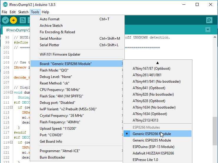
The WiFi Blaster board definition is not included with the Arduino ESP8266 board files, but it can be uploaded to as a Generic ESP8266 Module. Verify your settings look like below:
| Board: Generic ESP8266 Module | |
|---|---|
| Board | Generic ESP8266 Module |
| Flash Mode | QIO |
| Debug Level | None |
| Reset Method | ck |
| CPU Frequency | 80 MHz |
| Flash Size | 4M (1M SPIFFS) |
| Debug Port | Disabled |
| lwIP Variant | v2 Prebuilt (MSS=536) |
| Crystal Frequency | 26 MHz |
| Flash Frequency | 40MHz |
| Upload Speed | 115200 |
Auto vs. Manual Reset Into Bootloader
In addition to the RX and TX pins, the FTDI's DTR pin is used to reset the ESP8266 and get it into bootloader mode. The board includes circuitry to automatically reset and bootload the board; in most cases, you shouldn't have to do anything special to program it.
The auto-reset circuit can be a little flaky, however. If the board isn't taking a program, you may see an error like "error: espcomm_upload_mem failed".
If this shows up repeatedly, you may need to manually reset into bootloader mode be holding pin 0 low while resetting the ESP8266:
- Hold down the "0" button
- Press and release the "RST" button
- Release the "0" button
The timing of this can be a little tricky. Try resetting it into bootloader mode, then quickly uploading your sketch.
Decreasing the upload speed baud rate to something around 115200 bps can also help improve the reliability of the reset circuit.