SparkFun WiFi IR Blaster Hookup Guide
 jimblom,
  Englandsaurus
Hardware Overview
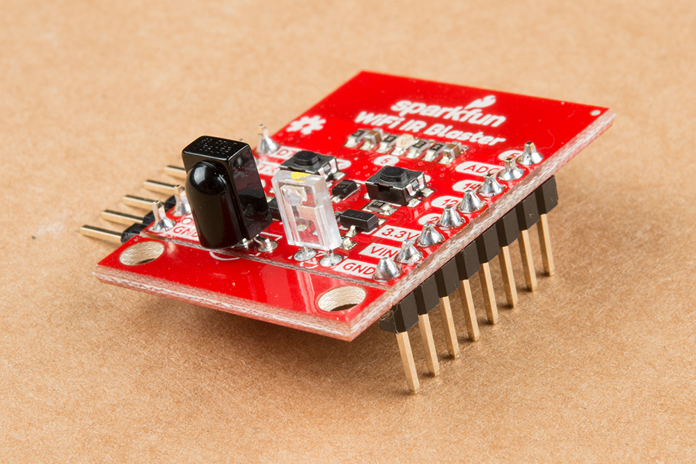
The WiFi IR Blaster is based around the ESP-12S ESP8266 module. This module equips the ESP8266 with a crystal, 4Mb flash, and PCB antenna -- just about everything it needs to get going. The antenna sits under the SparkFun logo, so try not to place anything that may interfere with WiFi signals near that area.
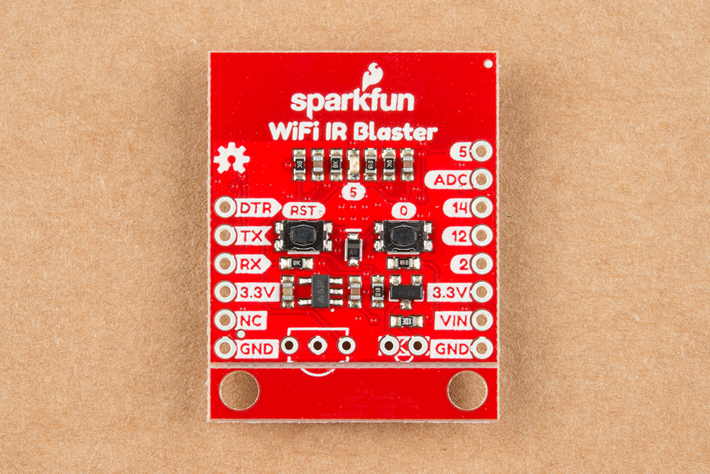
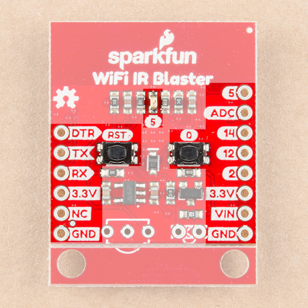
Supporting the ESP8266 are a reset and general purpose button, a user LED, and an array of pin breakouts.
Of course, there's also the IR emitter and detector. These components are packaged with the board, but not soldered in place. This allows you to solder both components at any angle your project requires. It also leaves the option to customize the board and spec out your own emitter and/or receiver.
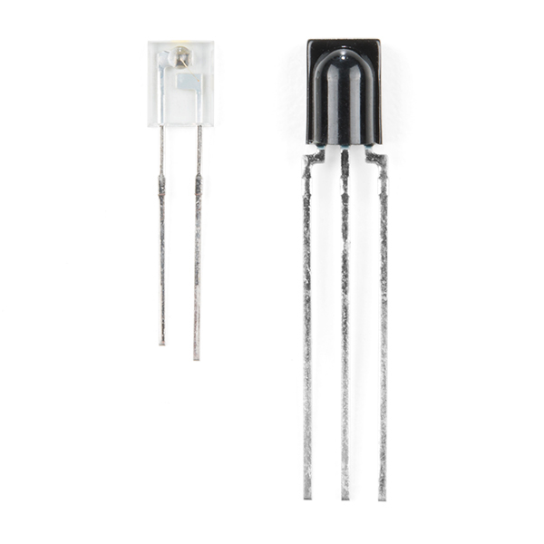
The IR emitter is a Lite-ON LTE-302. It's driven by an NPN transistor, which helps amplify the current through the LED.
The IR receiver is a TSOP38238. This is a simple IR receiver hard-coded to receive IR signals modulated at 38kHz.
Assembly Tips
Time to whip out a soldering iron! The IR emitter and receiver do not come soldered onto the WiFi IR Blaster. You'll also need to solder headers for programming and power supply pins.
While you have your iron out, you may also want to solder headers into the 6-pin serial header and the 8-pin power/GPIO header. Which headers you solder into the board ultimately depends on your application. I like soldering in a male right-angle header to the 6-pin header, which makes attaching the USB-to-serial board easier. Straight male headers work well for plugging the board into a bread- or perf-board.
Powering the WiFI IR Blaster
The WiFi IR Blaster includes a 3.3V low dropout regulator which can supply up to 600mA and handle voltage inputs up to 6V. To use this regulator, connect your power source to the VIN pin.
Alternatively, a pair of 3.3V pins are broken out on both headers. This pin directly supplies the ESP8266, so it should remain regulated to the range of ESP8266: 3.0V-3.6V.
⚡Powering via FTDI Header
The WiFi IR Blaster can be powered via the 3.3V pin on the 6-pin serial header. Voltage supplied to this pin should be regulated to 3.3V. Your power source will need to be able to supply at least 300mA, which most FTDI boards cannot do. We recommend the Beefy 3 FTDI Basic Breakout which can supply up to 600mA.
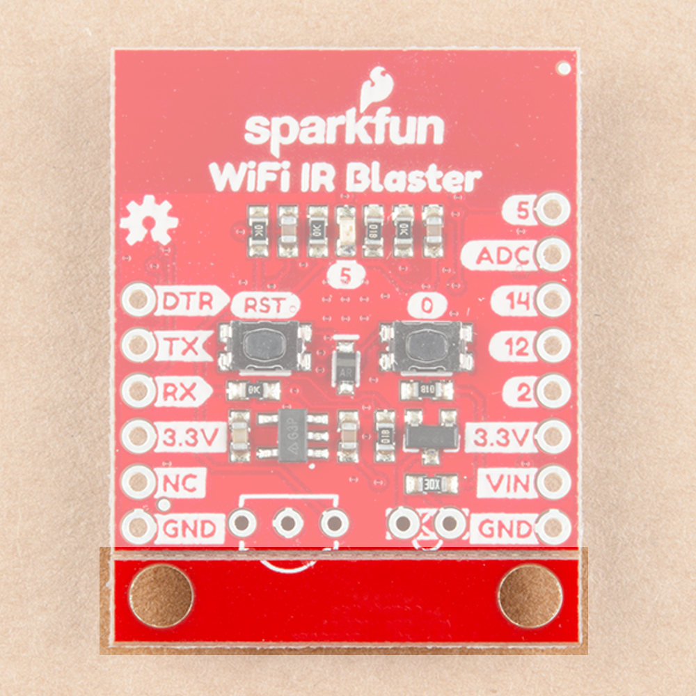
Removing the Standoff Edge
A pair of standoffs are provided towards the bottom of the WiFi IR Blaster. If you don't need these standoffs, and want to save some space, the standoff board can be removed by breaking it along the v-score line.