SparkFun LoRa Gateway 1-Channel Hookup Guide
Single-Channel LoRaWAN Gateway
Making a LoRa Gateway
Thanks to 915 MHz LoRa AND WiFi connectivity, the LoRa Gateway 1-Channel really shines as an inexpensive gateway in a LoRaWAN network. This section will show you how to make your own gateway and access it on the internet.
If you've followed along with this hookup guide then you should already be able to program the LoRa Gateway 1-Channel. The next step is to download a library to run LoRaWAN and modify it to suit our board and needs.
Download the Library
The ESP 1-ch Gateway code is hosted on GitHub by things4u. You can get the latest and greatest there, or download our archived copy here:
This repository includes both the Arduino sketch and the libraries it depends on. Before compiling the sketch you'll need to extract all libraries from the repository's "library" folder into your Arduino sketchbook's "libraries" folder. For more help installing the libraries, check out the Getting Started section of the README.
To open the example code, open the ESP-sc-gway.ino file. When the IDE loads, it should include another dozen-or-so tabs -- it's a hefty, but well-segmented sketch!
Configure the Gateway Sketch
Before uploading the ESP-1ch-Gateway sketch to your board, you'll need to make a handful of modifications to a couple of files. (Use Ctrl-F to search the file for the setting you want to modify) Here's a quick overview:
ESP-sc-gway.h
This file is the main source of configuration for the gateway sketch. The definitions you'll probably have to modify are:
- Radio
_LFREQ-- This sets the frequency range your radio will communicate on. Set this to either433(Asia),868(EU), or915(US)_SPREADING-- This sets the LoRa spread factor.SF7,SF8,SF9,SF10,SF11, orSF12can be used. Note that this will affect which devices your gateway can communicate with._CAD-- Channel Activity Detection. If enabled (set to 1) CAD will allow the gateway to monitor messages sent at any spread factor. The tradeoff if enabled: very weak signals may not be picked up by the radio.
- Hardware
OLED-- This board does not include an OLED, set this to 0._PIN_OUT-- This configures the SPI and other hardware settings. Set this to 6, we'll add a custom hardware definition later.CFG_sx1276_radio-- Ensure this is defined and CFG_sx1272_radio is not. This configures the LoRa radio connected to the ESP32.
- The Things Network (TTN)
_TTNSERVER-- The TTN router that your gateway will hand its data over to. router.eu.thethings.network recommended. See the note below._TTNPORT--1700is the standard port for TTN_DESCRIPTION-- Customize the name of your gateway_EMAIL-- Your email address, or that of the owner of the gateway_LATand _LON-- GPS coordinates of your gateway
- WiFi
- Add at least one WiFi network to the
wpas wpa[]array, but leave the first entry blank. For example:
- Add at least one WiFi network to the
language:c
wpas wpa[] = {
  { "" , "" },                          // Reserved for WiFi Manager
  { "my_wifi_network", "my_wifi_password" }
};
There are a lot of other values which can all optionally be configured. For a complete rundown, check out the Editing the ESP-sc-gway.h part of the README.
loramodem.h
This file defines how the LoRa modem is configured, including which frequency channels it can use and which pins the ESP32 uses to communicate with it. Be careful modifying most of the definitions in here, but one section you will have to modify is the _PIN_OUT declarations.
First, find the line that says #error "Pin Definitions _PIN_OUT must be 1(HALLARD) or 2 (COMRESULT)" and delete it. Then copy and paste these lines in its place (between the #else and #endif):
language:c
struct pins {
  uint8_t dio0 = 26;
  uint8_t dio1 = 33;
  uint8_t dio2 = 32;
  uint8_t ss = 16;
  uint8_t rst = 27; // Reset not used
} pins;
#define SCK  14
#define MISO 12
#define MOSI 13
#define SS  16
#define DIO0 26
The int freqs[] array can be adjusted, if you want to use different subbands, but, beyond that, there's not much else in here we recommend modifying.
Upload the Sketch
With your modifications made, try compiling and uploading the sketch to your ESP32. After it's uploaded, open up your serial monitor and set the baud rate to 115200. Debug messages here can be very handy, and finding your gateway's IP address is critical if you want to monitor the web server.
The sketch may take a long time to set up the first time through -- it will format your SPIFFS file system and create a non-volatile configuration file. Once that's complete, you should see the ESP32 attempt to connect to your WiFi network, then initialize the radio.
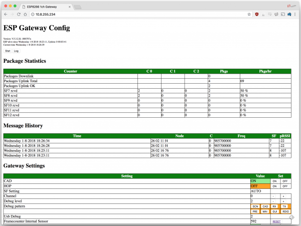
After the ESP32 has connected, look for it to print out an IP address. Open up your computer's web browser and plug that into the address bar. You should be greeted by the ESP Gateway Config web portal:
This web page can be used to monitor messages coming through and what frequencies and spread factors they came in on. It can also be used to change your gateway's configuration on-the-fly. You can adjust the channel or spread factor, or turn CAD on/off, or even turn on simplistic frequency-hopping.
Of course, to see any messages get through you'll need a LoRa device (or devices) set up to communicate with your gateway. Check out the next section for a quick guide on setting up a second ESP32 LoRa board as a LoRa device. Alternately if you have a different SparkFun LoRa-enabled product like the SAMD21 Pro RF follow that product's guide to set up a LoRaWAN device.
TroubleShooting
If you copy your IP address into the web browser and get a message saying the website cannot be reached, make sure your LoRaWAN and your computer are connected to the same network.
