SparkFun LoRa Gateway 1-Channel Hookup Guide
Hardware Overview
The LoRa Gateway 1-Channel is chock full of functionality:
- ESP32-WROOM-32 module
- WiFi, BT+BLE microcontroller
- Integrated PCB antenna
- Hope RFM95W LoRa modem
- Frequency range: 868/915 MHz
- Spread factor: 6-12
- SPI control interface
- U.FL antenna connector for LoRa radio
- Reset and ESP32 pin0 buttons
- 14 GPIO ESP32 pin-breakouts
- Power and user LEDs
- Qwiic connector
- CH340C USB-to-Serial interface
- Micro-B USB connector for power and programming
- Voltage input range: 3.3V-6V max
ESP32
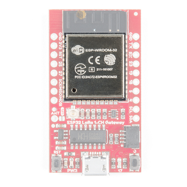
The brains of the gateway is an ESP32-WROOM-32 module, shown below. It has all the same features as the SparkFun ESP32 Thing rolled up into one sweet little package. WiFi, Bluetooth, 240 MHz processing speed, and a bunch of I/O pins make it a great foundation for the gateway.
RFM95W
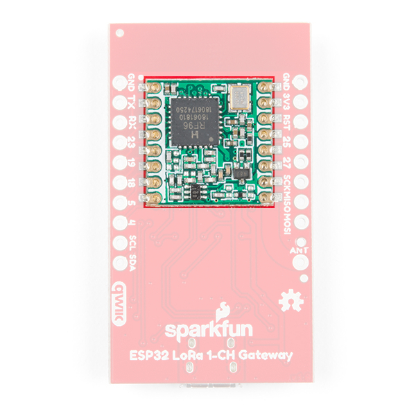
Every LoRa gateway needs to speak the Chirp Spread Spectrum (CSS) radio language and the RFM95W module does just that in the 915 MHz centered ISM band. The limitation on this device is it can only listen to one LoRa channel at a time, unlike full multi-channel LoRa gateways.
Antenna Connections
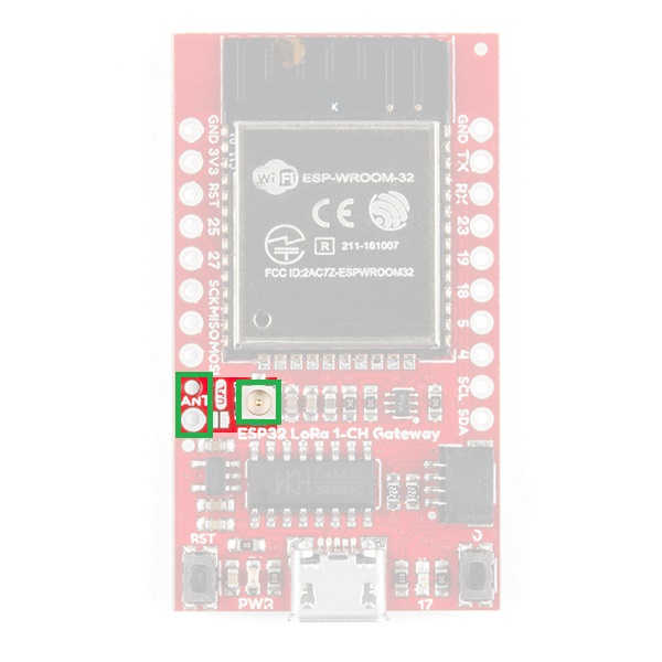
The LoRa Gateway 1-Channel sports both a through-hole antenna connection with strain relief as well as a U.FL connection for higher performance antennas.
User Buttons, LEDs, and USB
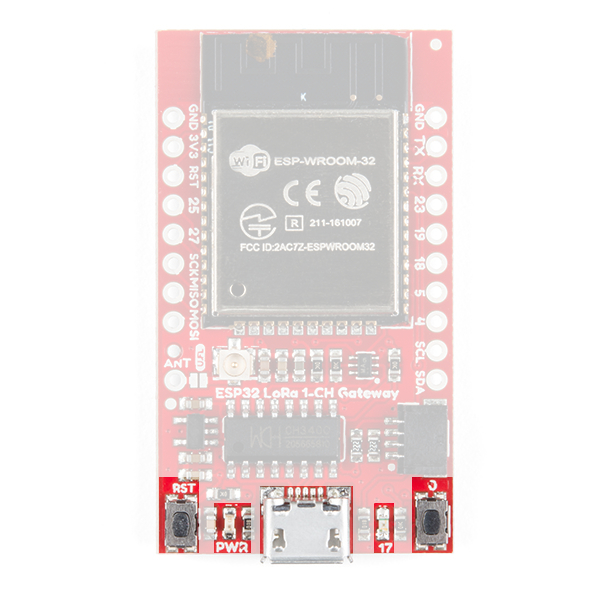
On the bottom left side of the board you will find the power led and the reset button. Opposing are a button connected to pin 0 and an led connected to pin 17. The buttons exist to force the ESP32 into programming mode in case the automatic process by the CH340C USB-serial bridge chip fails, but after that you can use button 0 as an active-low input for your sketch. The ESP also uses the USB-serial bridge as the default serial port so there's nothing else you need to connect to your computer.
Qwiic Connector
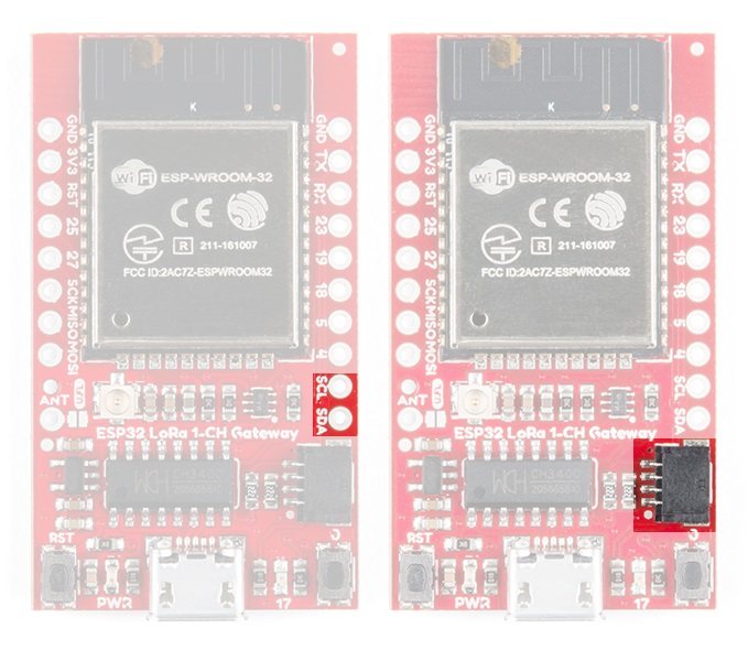
The default I2C lines of the ESP32 are broken out to both PTH pads and the super-convenient Qwiic connector. This means you can easily add peripherals to your gateway or sensors to your LoRa device!
IO Pins
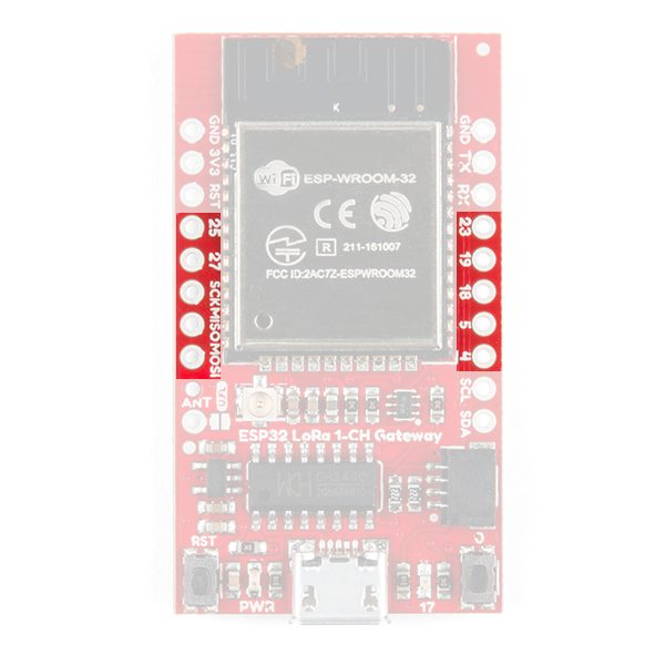
For anything other than I2C you can use the SPI lines and/or 7 GPIO pins which are all broken out to PTH pads around the board.
