SparkFun LoRa Gateway 1-Channel Hookup Guide
 jimblom,
  Liquid Soulder
 Introduction
If you are using this with the older version [SPX-14893], please refer to the ESP32 LoRa 1-CH Gateway, LoRaWAN, and the Things Network tutorial.
So you've designed an automatic shepherding robot but you still have to go out to the field to make sure it is working? Worry no more, you can use long-range radio to keep tabs on that 'bot through the internet of things! All you need is an interpreter to speak the language, and the LoRa Gateway 1-Channel does just that.
The LoRa Gateway 1-Channel is a monster 3-network capable device thanks to an ESP32 module and a RFM95W LoRa modem. The RFM95W handles the 915 MHz band while the ESP32 takes care of bluetooth and WiFi. One of the ideal uses is to convert LoRa (Long Range) radio messages into data packets that you can access via the web, but of course the flexibility it offers can be put to many more uses!
This guide will go over the hardware on the board, how to program it in Arduino, how to create a single channel LoRa gateway, and finally how to create a LoRa device on The Things Network.
Required Materials
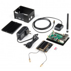
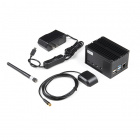
The LoRa Gateway 1-Channel can act as either a gateway or a device, but not both at the same time. To really be sure that your setup works as expected you should have another LoRa device to listen to, and/or another LoRa gateway to transmit to. The good news is that the LoRa Gateway 1-Channel can act as both so if you have two then you're all set.
If you only have one LoRa 1-Channel gateway then you can choose one of these products to test it:

To program the LoRa Gateway 1-Channel you will need a micro-B USB cable and a computer with the Arduino IDE installed. If you want to make a permanent installation away from your computer then consider powering it with a USB wall adapter or USB battery pack.
Tools
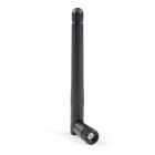
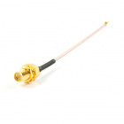
To use the 915 MHz radio on the gateway you will need an antenna - for which you have two choices. You may cut a length of solid-core wire to approx 3" or use a 915 MHz antenna with a U.FL connector. If you choose the wire route then you will also need a soldering iron and tools to attach your antenna to the board.

Weller WLC100 Soldering Station
TOL-14228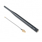
Suggested Reading
If you aren’t familiar with the following concepts, we recommend checking out these tutorials before continuing.
How to Solder: Through-Hole Soldering
Installing Arduino IDE
Serial Terminal Basics
SparkFun Serial Basic CH340C Hookup Guide
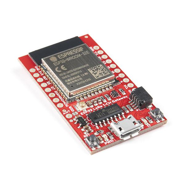
Hardware Overview
The LoRa Gateway 1-Channel is chock full of functionality:
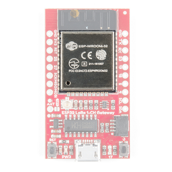
- ESP32-WROOM-32 module
- WiFi, BT+BLE microcontroller
- Integrated PCB antenna
- Hope RFM95W LoRa modem
- Frequency range: 868/915 MHz
- Spread factor: 6-12
- SPI control interface
- U.FL antenna connector for LoRa radio
- Reset and ESP32 pin0 buttons
- 14 GPIO ESP32 pin-breakouts
- Power and user LEDs
- Qwiic connector
- CH340C USB-to-Serial interface
- Micro-B USB connector for power and programming
- Voltage input range: 3.3V-6V max
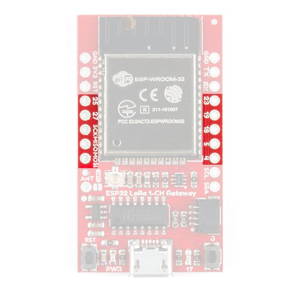
ESP32
The brains of the gateway is an ESP32-WROOM-32 module, shown below. It has all the same features as the SparkFun ESP32 Thing rolled up into one sweet little package. WiFi, Bluetooth, 240 MHz processing speed, and a bunch of I/O pins make it a great foundation for the gateway.
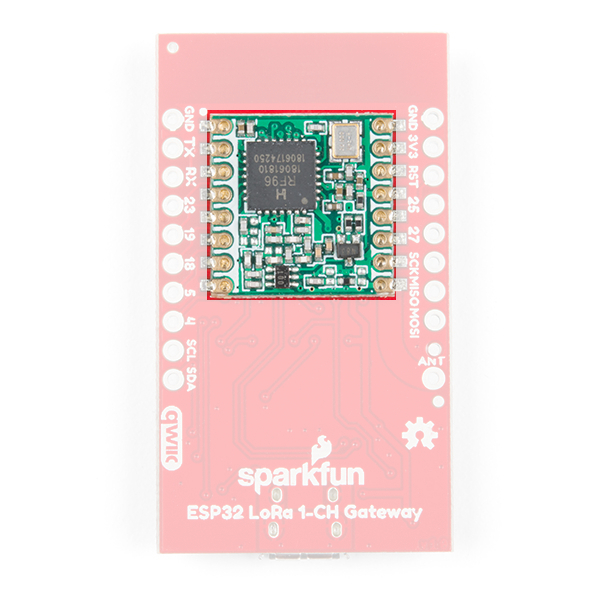
RFM95W
Every LoRa gateway needs to speak the Chirp Spread Spectrum (CSS) radio language and the RFM95W module does just that in the 915 MHz centered ISM band. The limitation on this device is it can only listen to one LoRa channel at a time, unlike full multi-channel LoRa gateways.
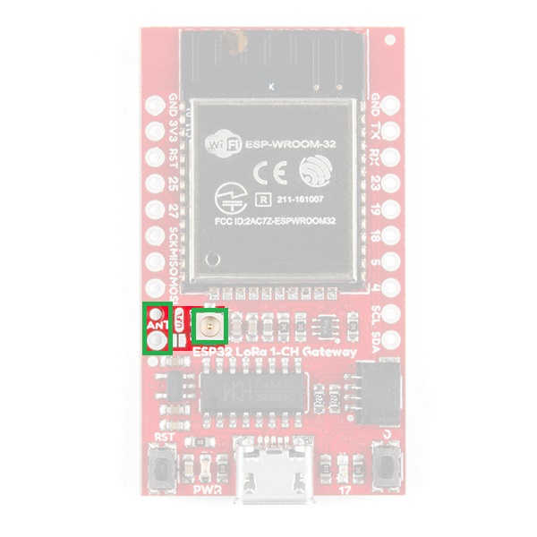
Antenna Connections
The LoRa Gateway 1-Channel sports both a through-hole antenna connection with strain relief as well as a U.FL connection for higher performance antennas.
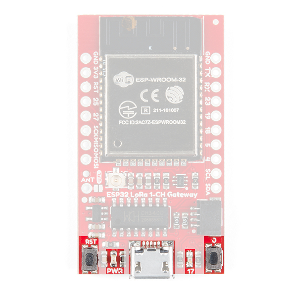
User Buttons, LEDs, and USB
On the bottom left side of the board you will find the power led and the reset button. Opposing are a button connected to pin 0 and an led connected to pin 17. The buttons exist to force the ESP32 into programming mode in case the automatic process by the CH340C USB-serial bridge chip fails, but after that you can use button 0 as an active-low input for your sketch. The ESP also uses the USB-serial bridge as the default serial port so there's nothing else you need to connect to your computer.
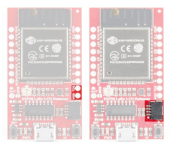
Qwiic Connector
The default I2C lines of the ESP32 are broken out to both PTH pads and the super-convenient Qwiic connector. This means you can easily add peripherals to your gateway or sensors to your LoRa device!
IO Pins
For anything other than I2C you can use the SPI lines and/or 7 GPIO pins which are all broken out to PTH pads around the board.
Programming the ESP32 With Arduino
We will be using the Arduino IDE to upload new code to the Gateway. To get everything working the way it oughtta you'll have to install the ESP32 Arduino core - a set of tools and code that translates Arduino code to something that the ESP32 understands. You can also make life a little bit easier by installing a custom board definition for the LoRa Gateway 1-Channel.
Install ESP32 Arduino Core
The ESP32's relationship with Arduino is growing and now it is very easy to install the core - the Arduino IDE can handle it nearly on its own. All you need to do is make sure you have Arduino IDE version 1.8 or later, then paste
language:c
https://dl.espressif.com/dl/package_esp32_index.json
into the Additional Board Manager URLs field of the preferences window, like this:
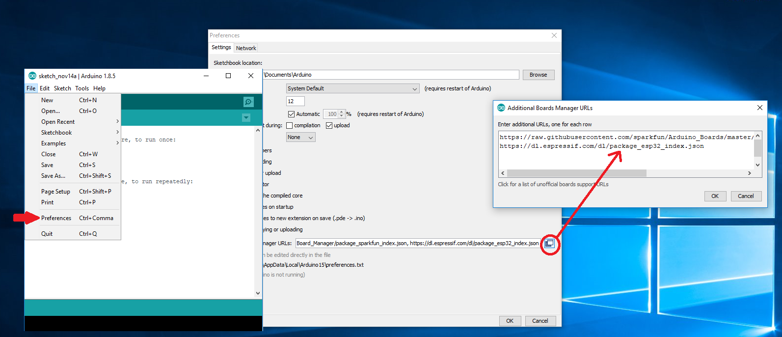
Now accept the changes and restart the Arduino IDE. Next open the Board Manager from the top of Tools > Board and search for ESP32. Click "Install" on the search result, after a little while the text besides the name should change to "Installed." Re-start the IDE for good measure.
The remaining portions of this guide will focus on sending a "Hello world!" message from a LoRa device to the internet.
LoRaWAN Roadmap
LoRa, LoRaWAN, and the Internet of Things is a very big topic. Before we go and get lost in code let's make sure we know what the end goal is and roughly how we plan to get there.
Let's start with the Internet of Things (IoT). Really all IoT is is the idea that we can add inter-connectivity to a large portion of the things we interact with on a day-to-day basis. For example, if your refrigerator kept track of what was inside and could talk to your cell phone, then when you were at the store you wouldn't be left wondering if you need another case of kombucha to pair with the 6 bags of quinoa chips you just bought. So the Internet of Things is about connectivity.
Connectivity is pretty well-solved in the home with WiFi and Bluetooth, but what if your refrigerator was in the middle of a field without access to the internet? (Okay bad example, but the refrigerator is just a stand-in for your connected device). This is where LoRa comes in. LoRa is "Long Range" radio which was designed for low power consumption and long range transmissions at the expense of bandwidth. This means you can send a little bit of data a long way.
Okay, so now your field refrigerator can send messages a long way -- ideally far enough to reach to the nearest Starbucks - or any other place that has WiFi. Of course nobody at the coffee shop knows about your far-distant fridge (and certainly the WiFi modems won't be listening for messages) so you need something that is dedicated to bridge from LoRa messages to internet traffic - called a "gateway." As long as you have something that can speak both LoRa and "Internet" then you could make your own solution, but there is a easier and better option. This is where LoRaWAN comes in.
LoRaWAN is a public specification for the system that would be at Starbucks listening for messages from the fridge. Two important benefits of LoRaWAN are that your data is encrypted during transmission and that your fridge could get up and walk to the next state over (again - just a metaphor!) and the messages could still be picked up by a gateway that someone else had built. Since the messages are secure that person won't know about your stinky cheese but the message will still get back to you over the internet. Groups like The Things Network organize everyone's efforts to make this possible.
The goal of this guide is to walk through that whole process and get a "Hello World!" message from a remote device, into a gateway, and onto the internet. We will go a little bit out-of-order because it makes things easier. First we will create the gateway, then we will fire up a device to send the data, and finally we will create an internet application to look for the data.
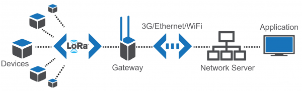
Image courtesy of Jensd. If you want to read more about what LoRa and LoRaWAN are check out this great post on Jensd's I/O Buffer.
Your Device
A "device" is the remote system that is sending (and in some cases receiving) data. We will set up a device to actually send the "Hello World!" message in the section "Turning a Gateway into A Device."
Your Gateway
The name of the ESP LoRa Gateway 1-Channel is a dead giveaway. With all its glorious wireless connectivity it acts as the bridge that speaks both WiFi and LoRa. The section "Single-Channel LoRaWAN Gateway" will cover all the steps you need to make this part.
Your Application
An "application" is the software that you set up to look for and handle the messages that make it to the internet. We will create an application using The Things Network that will be on the lookout for your "Hello World!" message.
Single-Channel LoRaWAN Gateway
Making a LoRa Gateway
Thanks to 915 MHz LoRa AND WiFi connectivity, the LoRa Gateway 1-Channel really shines as an inexpensive gateway in a LoRaWAN network. This section will show you how to make your own gateway and access it on the internet.
If you've followed along with this hookup guide then you should already be able to program the LoRa Gateway 1-Channel. The next step is to download a library to run LoRaWAN and modify it to suit our board and needs.
Download the Library
The ESP 1-ch Gateway code is hosted on GitHub by things4u. You can get the latest and greatest there, or download our archived copy here:
This repository includes both the Arduino sketch and the libraries it depends on. Before compiling the sketch you'll need to extract all libraries from the repository's "library" folder into your Arduino sketchbook's "libraries" folder. For more help installing the libraries, check out the Getting Started section of the README.
To open the example code, open the ESP-sc-gway.ino file. When the IDE loads, it should include another dozen-or-so tabs -- it's a hefty, but well-segmented sketch!
Configure the Gateway Sketch
Before uploading the ESP-1ch-Gateway sketch to your board, you'll need to make a handful of modifications to a couple of files. (Use Ctrl-F to search the file for the setting you want to modify) Here's a quick overview:
ESP-sc-gway.h
This file is the main source of configuration for the gateway sketch. The definitions you'll probably have to modify are:
- Radio
_LFREQ-- This sets the frequency range your radio will communicate on. Set this to either433(Asia),868(EU), or915(US)_SPREADING-- This sets the LoRa spread factor.SF7,SF8,SF9,SF10,SF11, orSF12can be used. Note that this will affect which devices your gateway can communicate with._CAD-- Channel Activity Detection. If enabled (set to 1) CAD will allow the gateway to monitor messages sent at any spread factor. The tradeoff if enabled: very weak signals may not be picked up by the radio.
- Hardware
OLED-- This board does not include an OLED, set this to 0._PIN_OUT-- This configures the SPI and other hardware settings. Set this to 6, we'll add a custom hardware definition later.CFG_sx1276_radio-- Ensure this is defined and CFG_sx1272_radio is not. This configures the LoRa radio connected to the ESP32.
- The Things Network (TTN)
_TTNSERVER-- The TTN router that your gateway will hand its data over to. router.eu.thethings.network recommended. See the note below._TTNPORT--1700is the standard port for TTN_DESCRIPTION-- Customize the name of your gateway_EMAIL-- Your email address, or that of the owner of the gateway_LATand _LON-- GPS coordinates of your gateway
- WiFi
- Add at least one WiFi network to the
wpas wpa[]array, but leave the first entry blank. For example:
- Add at least one WiFi network to the
language:c
wpas wpa[] = {
  { "" , "" },                          // Reserved for WiFi Manager
  { "my_wifi_network", "my_wifi_password" }
};
There are a lot of other values which can all optionally be configured. For a complete rundown, check out the Editing the ESP-sc-gway.h part of the README.
loramodem.h
This file defines how the LoRa modem is configured, including which frequency channels it can use and which pins the ESP32 uses to communicate with it. Be careful modifying most of the definitions in here, but one section you will have to modify is the _PIN_OUT declarations.
First, find the line that says #error "Pin Definitions _PIN_OUT must be 1(HALLARD) or 2 (COMRESULT)" and delete it. Then copy and paste these lines in its place (between the #else and #endif):
language:c
struct pins {
  uint8_t dio0 = 26;
  uint8_t dio1 = 33;
  uint8_t dio2 = 32;
  uint8_t ss = 16;
  uint8_t rst = 27; // Reset not used
} pins;
#define SCK  14
#define MISO 12
#define MOSI 13
#define SS  16
#define DIO0 26
The int freqs[] array can be adjusted, if you want to use different subbands, but, beyond that, there's not much else in here we recommend modifying.
Upload the Sketch
With your modifications made, try compiling and uploading the sketch to your ESP32. After it's uploaded, open up your serial monitor and set the baud rate to 115200. Debug messages here can be very handy, and finding your gateway's IP address is critical if you want to monitor the web server.
The sketch may take a long time to set up the first time through -- it will format your SPIFFS file system and create a non-volatile configuration file. Once that's complete, you should see the ESP32 attempt to connect to your WiFi network, then initialize the radio.
After the ESP32 has connected, look for it to print out an IP address. Open up your computer's web browser and plug that into the address bar. You should be greeted by the ESP Gateway Config web portal:

This web page can be used to monitor messages coming through and what frequencies and spread factors they came in on. It can also be used to change your gateway's configuration on-the-fly. You can adjust the channel or spread factor, or turn CAD on/off, or even turn on simplistic frequency-hopping.
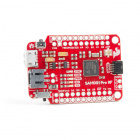
Of course, to see any messages get through you'll need a LoRa device (or devices) set up to communicate with your gateway. Check out the next section for a quick guide on setting up a second ESP32 LoRa board as a LoRa device. Alternately if you have a different SparkFun LoRa-enabled product like the SAMD21 Pro RF follow that product's guide to set up a LoRaWAN device.
TroubleShooting
If you copy your IP address into the web browser and get a message saying the website cannot be reached, make sure your LoRaWAN and your computer are connected to the same network.
Turning a Gateway Into a Device
If you have a pair of ESP32 gateway's you can use one of them as a LoRaWAN device. This section will get you set up with our preferred LoRaWAN Arduino library and a simple example sketch to get started.
Get the Arduino-LMIC Library to Set Up a Device
If you have a pair of ESP32 Gateways and want to set one of them up as a LoRa device, we recommend using the Arduino-LMIC library. There seem to be many versions of the Arduino-LMIC library hanging around, we've had good success with the library forked by mcci-catena. If you don't want to use GitHub you can download an archived .zip file here. It will work for this guide but it may not be completely up-to-date.
To install the library, download the ZIP file and use the Arduino's "Add ZIP library" feature (Sketch > Include Library > Add .ZIP Library) to import the zip file into your Arduino sketchbook.
Configure LMIC
Before can use an example sketch in the LMIC library, you'll need to configure it. To configure the library, navigate to the "arduino-lmic" library in your ..{Arduino Sketchbook}/libraries folder. Then go to project_config and open lmic_project_config.h.
Here you'll define which frequency bands your LoRa device will use. You can also turn on debugging and enable/disable a host of features with definitions in this file.
Make sure you uncomment one (and only one!) of the "CFG..." declarations. If you're in the USA, uncomment #define CFG_us915. Ultimately, this frequency should match what you set in the gateway.
Below is my config file -- I've turned on debugging, because I'm a log junkie.
language:c
// project-specific definitions
//#define CFG_eu868 1
#define CFG_us915 1
//#define CFG_au921 1
//#define CFG_as923 1
// #define LMIC_COUNTRY_CODE LMIC_COUNTRY_CODE_JP   /* for as923-JP */
//#define CFG_in866 1
#define CFG_sx1276_radio 1

//#define LMIC_PRINTF_TO Serial
#define LMIC_DEBUG_LEVEL 2

//#define DISABLE_INVERT_IQ_ON_RX
If you try to use the "raw" example in this library, you'll need to uncomment DISABLE_INVERT_IQ_ON_RX, otherwise keep it commented-out.
Modify the "SPI.begin" call
Just to be sure your pin definitions are correct, I recommend modifying the SPI.begin line in arduino-lmic/src/hal/hal.cpp (line 136) to:
language:c
SPI.begin(14, 12, 13, 16);
This will ensure that your SPI pins are set correctly -- this may only be necessary if you're not using the custom "SparkFun LoRa gateway 1-Channel" Arduino board.
Load the Single-Channel Device Example
We've taken one of the examples in the Arduino-LMIC library and modified it to work more reliably with a single-channel gateway.
Click the button below to download the example. Then open up ESP-1CH-TTN-Device-ABP.ino:
Among the modifications in this example are the pin map between radio and ESP32 -- set with these lines:
language:c
const lmic_pinmap lmic_pins = {
  .nss = 16,
  .rxtx = LMIC_UNUSED_PIN,
  .rst = 5,
  .dio = {26, 33, 32},
};
We've also modified the enabled channels to only use a single channel with the lines below (note this modification hasn't yet been tested on non-US frequency bands).
language:c
// First disable all sub-bands
for (int b = 0; b < 8; ++b) {
  LMIC_disableSubBand(b);
}
// Then enable the channel(s) you want to use
LMIC_enableChannel(8); // 903.9 MHz
The spread factor is set near the end of setup() with the LMIC_setDrTxpow(DR_SF7, 14); line. This can be replaced with DR_SF8, DR_SF9, or DR_SF10 at the default 903.9MHz frequency.
You can't compile successfully until you fill in these lines:
// LoRaWAN NwkSKey, network session key
// This is the default Semtech key, which is used by the early prototype TTN
// network.
static const PROGMEM u1_t NWKSKEY[16] = { PASTE_NWKSKEY_KEY_HERE };

// LoRaWAN AppSKey, application session key
// This is the default Semtech key, which is used by the early prototype TTN
// network.
static const u1_t PROGMEM APPSKEY[16] = { PASTE_APPSKEY_KEY_HERE };

// LoRaWAN end-device address (DevAddr)
static const u4_t DEVADDR = 0xPASTE_DEV_ADDR_HERE;
with something. If you want to test the gateway right now go ahead and fill the two arrays with 16 bytes each and the DEVADDR with a 4-byte wide number. If you do this and upload the code then you should see the gateway receiving messages. (If you're having trouble make sure that the device and the gateway are configured to use the same channel and spreading factor).
If you are OK waiting then leave these blank until you get your actual keys and device address from The Things Network in the next section.
Routing Into The Things Network
The final components to a LoRaWAN network are a server and application. Although it is possible to make your own server we've already configured the gateway to send data to The Things Network through one of their routers like "router.eu.thethings.network". This is an easy and free way to get started with LoRaWAN so we recommend starting this way.
Single-Channel Blues
At the trade-off of being low-cost, this gateway is only capable of monitoring a single LoRa channel on a limited set of spread factors. Single-channel gateway's don't get much support from LoRaWAN platforms like The Things Network, as they are not, necessarily, LoRaWAN-compliant. They are, however, a great way to begin exploring the world of LoRa and LoRaWAN!
If you haven't already, head to thethingsnetwork.org and create an account. Once that's done, go to your Console.
Create an Application
If your data is being sent to The Things Network's servers then you can create an application to access that data. This works by registering devices with unique cryptographic keys so that your data is only visible to you.
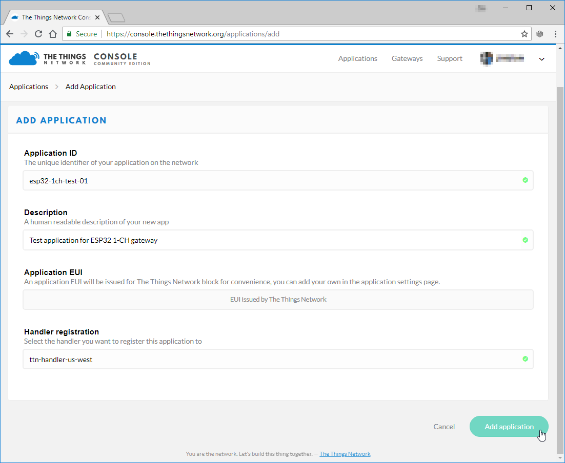
In order to register a device, you first need to create an application to house it under. In the console, click "Applications" then click "add application".
Fill out any ID and description you'd like. The Application EUI will automatically be generated when you create the application. You can also pick your preferred handler for the application (e.g. ttn-handler-us-west).
Create and Configure a Device
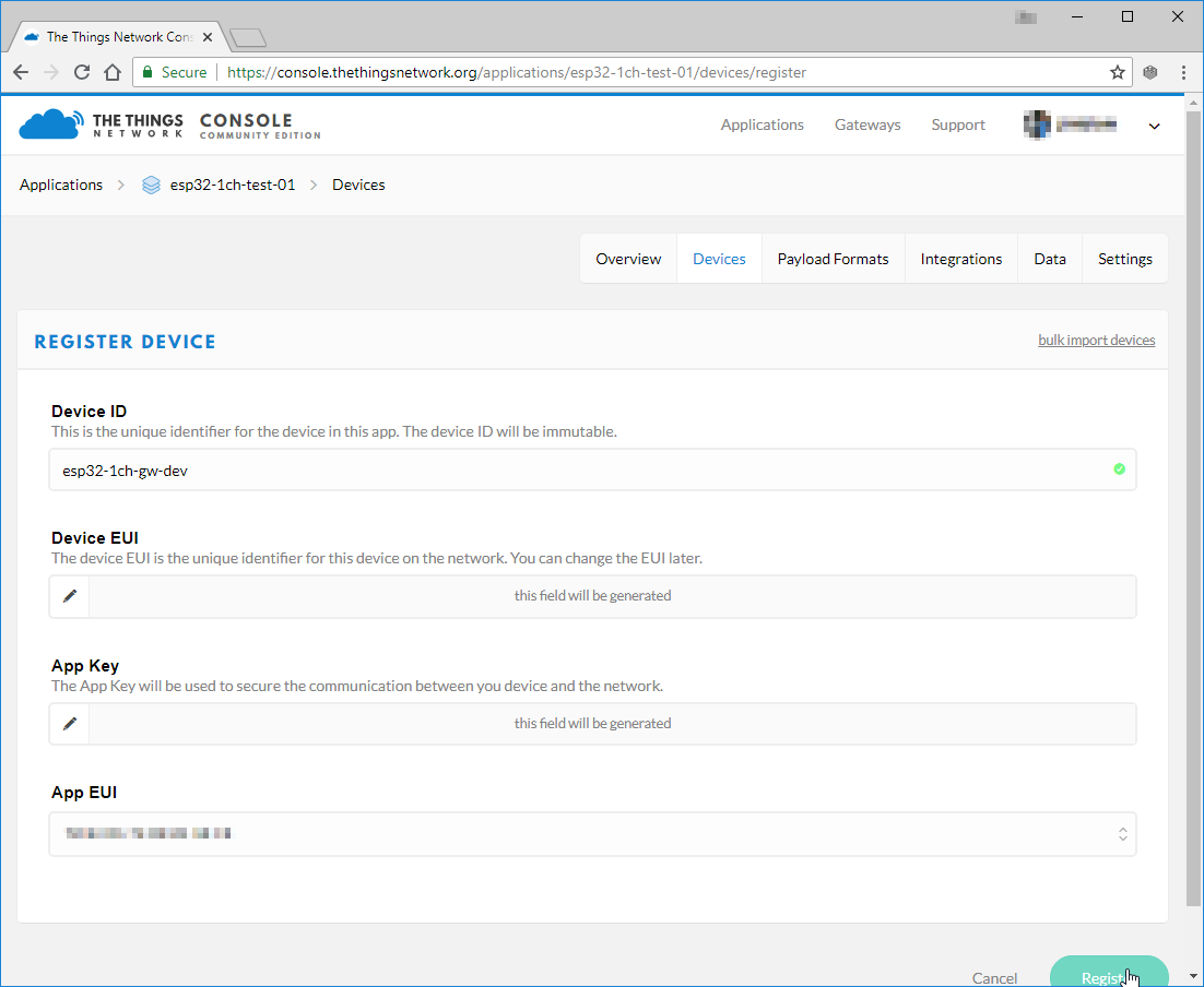
Next register a device in your application. Under the "Devices" section, click "register device".
This is again pretty simple. Fill out a unique device ID, click the "generate" button under "Device EUI" to automatically generate a EUI. Then click "Register."
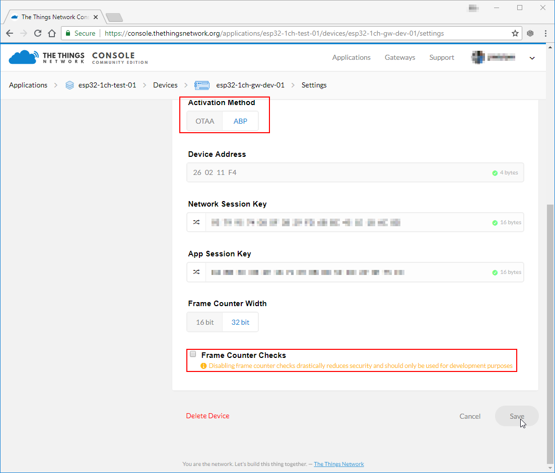
This example sketch only supports ABP activation, so you'll need to modify that in the device settings. In the "Device Overview" page, click "Settings". From there, under "Activation Method" click ABP. I also recommend disabling Frame Counter Checks. The gateway is capable of frame-counter checks, but it can get out of sync -- especially if you have another gateway nearby.
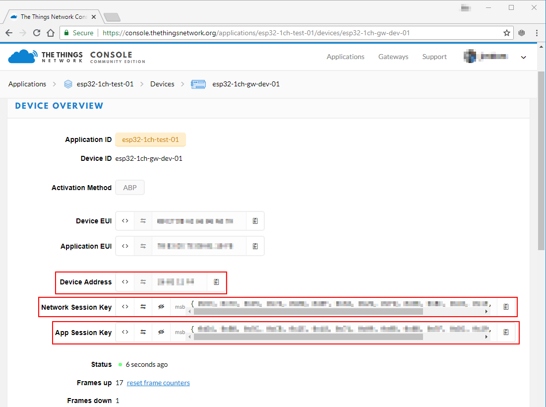
Save the settings and go back to your "Device Overview" page. You should see new keys, including "Network Session Key", "App Session Key", and "Device Address." These will need to be plugged into the device sketch and uploaded to the device - which we will cover in the next section.
Update the Example Code
With your application, network session, and device keys in-hand, you're ready to finish configuring the ESP32 LoRa device sketch and start posting data!
On the "Device Overview" page, click the "code" symbol (<>) next to "Network Session Key" and "App Session Key" -- this will make the key visible and display it as a 16-byte array. Copy each of those keys, and paste them in place of the {PASTE KEY HERE} place-holders. "Network Session Key" should be pasted into the NWKSKEY variable and "App Session Key" should be pasted into the APPSKEY variable.
The DEVADDR variable expects a single 32-bit variable, so copy the "Device Address" key as shown and paste that into the PASTE_DEV_ADDR_HERE placeholder.
Here's an example of what your three constants should look like once done:
language:c
// LoRaWAN NwkSKey, network session key
// This is the default Semtech key, which is used by the early prototype TTN
// network.
static const PROGMEM u1_t NWKSKEY[16] = { 0x01, 0x23, 0x45, 0x67, 0x89, 0xAB, 0xBD, 0xEF, 0x01, 0x23, 0x45, 0x67, 0x89, 0xAB, 0xCD, 0xEF };

// LoRaWAN AppSKey, application session key
// This is the default Semtech key, which is used by the early prototype TTN
// network.
static const u1_t PROGMEM APPSKEY[16] = { 0xFE, 0xDC, 0xBA, 0x98, 0x76, 0x54, 0x32, 0x10, 0xEE, 0xDC, 0xAA, 0x98, 0x76, 0x54, 0x32, 0x10 };

// LoRaWAN end-device address (DevAddr)
static const u4_t DEVADDR = 0x01234567;
And that's it! Now upload the code to your LoRa Gateway 1-Channel board (the one that is supposed to be the device, that is!)
Testing the Code
After setup, the device should immediately send a "Hello, World" message. It'll continue to send a message every minute or any time the "0" button on the board is pressed.
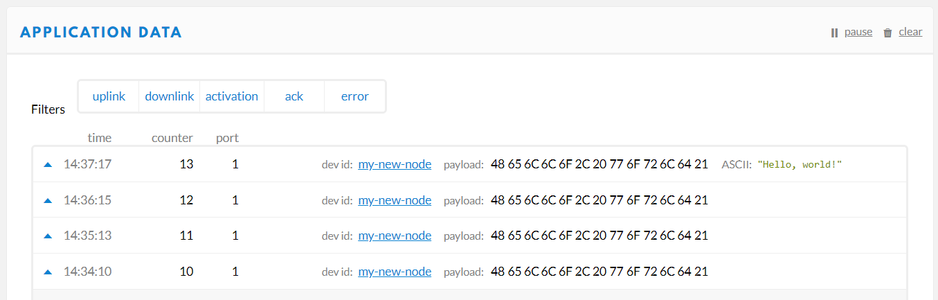
To check if your gateway is receiving the message, you can either check the Serial Monitor or monitor the ESP Gateway Config page served by the gateway. Every time a message is received it should be added to the "Message History" table.
If messages are getting through to your gateway, click the "Data" tab on your device to check for new messages.
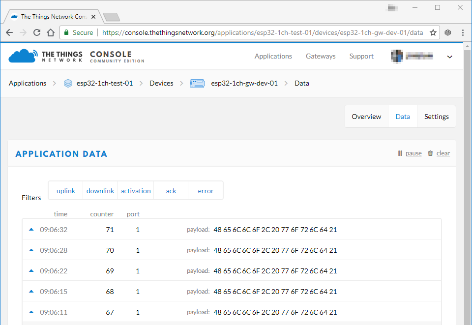
The message's payload -- which was encrypted between leaving the device and getting into your application -- should be a series of hex values corresponding to "Hello, world".
Decoding the Message
You may have noticed in the Application Data window that your payload is shown in raw bytes. In order to see "Hello, World!" encoded in ASCII, the way you sent it, you'll need to decode the payload. The Things Network includes tools for doing this right in the console! Navigate to the Application Overview page for your application and click on the Payload Formats tab. This menu allows you to write functions which will be applied to all incoming packets for this application.
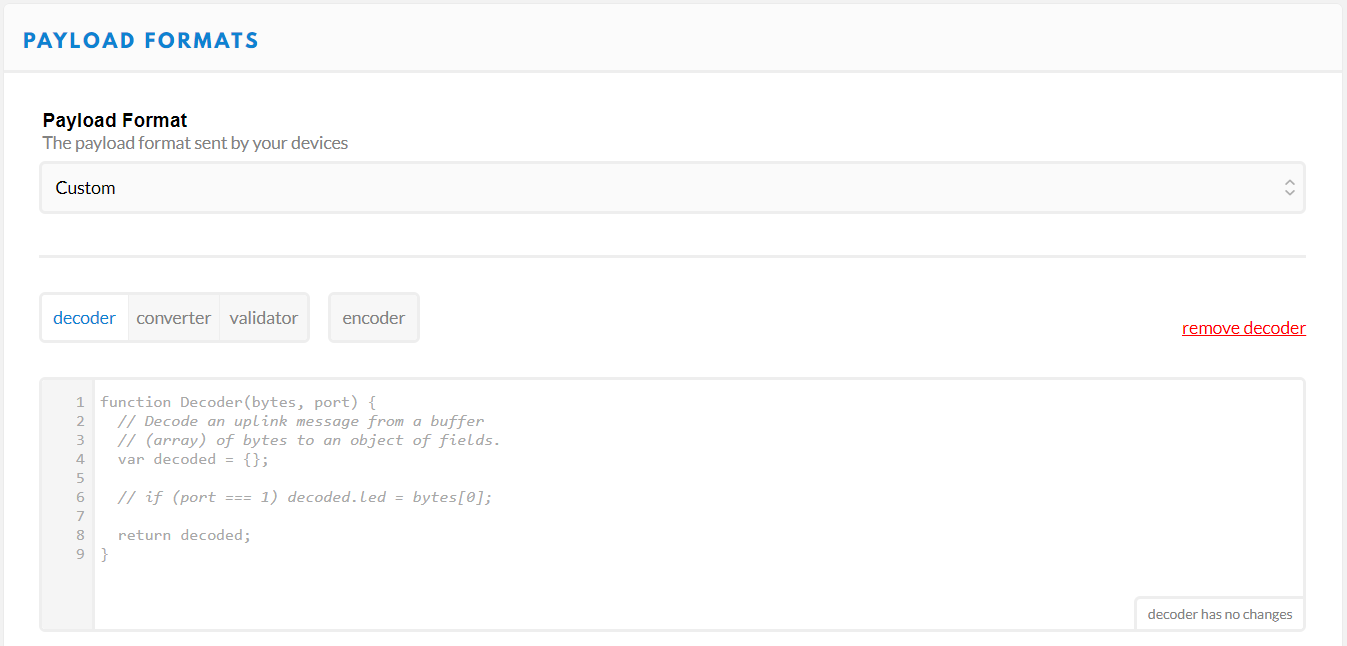
So let's write our own decoder. We need to take the raw byte data and return a string that contains all of the characters corresponding to each byte. Take a look at this solution and then we'll walk through it:
language:js
function Decoder(bytes, port) {

    return {
        ASCII: String.fromCharCode.apply(null, bytes)
    };

}
Decoder is a Javascript function that The Things Network has already set up for us. It takes two arguments called bytes, an array containing our payload, and port, the LoRaWAN™ "FPort" of the packet. FPort identifies the end application or service that the packet is intended for. Port 0 is reserved for MAC messages. We don't need to know anything about the port number for our example.
We can return any value that we want from the Decoder function and it will appear alongside our payload in the Application Data window. In the example above, I've created a new property called "ASCII" which is equal to String.fromCharCode.apply(null, bytes). To break this down a little more, we're returning a new String object called "ASCII," and we're using the Javascript apply() method to call fromCharCode() with the argument bytes and stuff the result into our new String. The fromCharCode() method simply steps through each byte in the array bytes (which, remember, contains our payload) and returns the ASCII character represented by that character code.
After copying the above code into your decoder function, scroll down and click the save payload functions button. Now return to the Application Data window and you should see that all packets received after the decoder function was changed now have a new property:
Our packet has been decoded! Excellent!
Troubleshooting
If messages are not getting to your gateway, first make sure the channel and spread factor match up. Left unchanged, the device example code should be sending data out on the 903.9MHz channel at a spread factor of 7 (That's assuming you've set the LMIC library to CFG_us915. If it's set to a European frequency spectrum, it'll be 868.1MHz, SF7).
You can use the gateway's web server to adjust these setting on the fly. Note that the channel numbers should sequentially match the freqs array in loraModem.h -- e.g. channel 0 should be 903.9MHz (again, assuming US frequencies).
If messages are getting to your gateway, but not showing up on your TTN device console, consider changing the _TTNSERVER variable in "ESP-sc-gway.h". I haven't had success with the us-west router, but "router.eu.thethings.network" has worked perfectly (even in the US).
Resources and Going Further
Thanks for coming on this single-channel LoRaWAN gateway journey with us! Here are a few links and documents that might prove handy as you continue exploring the world of LoRa with this board:
- The Things Network
- Product Repository -- GitHub repository where you can find all of our latest hardware and software design files.
- Hardware
- Schematic -- PDF schematic
- Eagle Files -- PCB design files
- ESP32-WROOM-32E Datasheet -- Datasheet for the ESP32 WROOM module
- RFM95W Datasheet -- Datasheet for the RFM95W LoRa radio module
- Software
- ESP-1ch-Gateway-v5.0 -- Single-Channel LoRaWAN Gateway Arduino firmware used in this tutorial.
- Arduino-LMIC library -- LoRaMAC-in-C (LMIC) Arduino library used to create LoRaWAN devices.
- ESP-1CH-TTN-Device-ABP -- Single-channel LoRaWAN device example using the Arduino-LMIC library.
- Libraries Archived for this Tutorial
Need Inspiration? Check out some of these fun IoT tutorials from SparkFun: