ESP32 LoRa 1-CH Gateway, LoRaWAN, and the Things Network
Introduction

Experimental Products: SparkX products are rapidly produced to bring you the most cutting edge technology as it becomes available. These products are tested but come with no guarantees. Live technical support is not available for SparkX products.
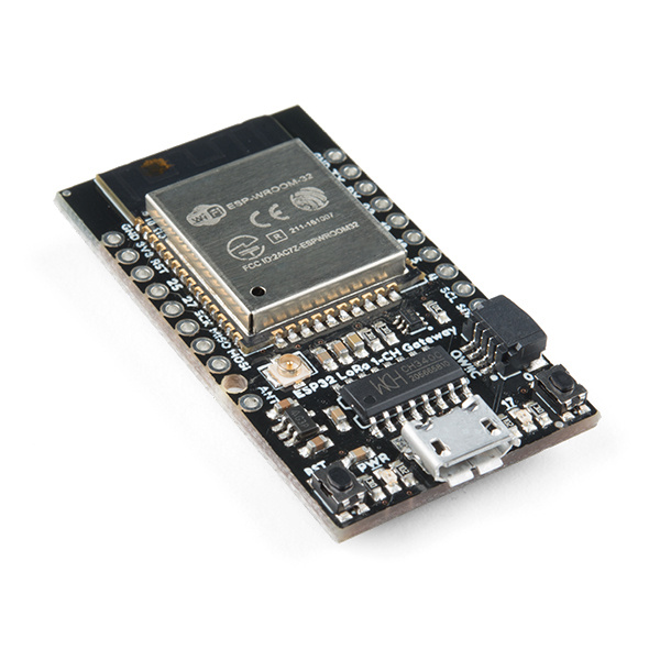
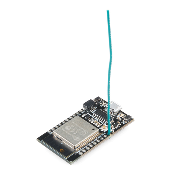
The ESP32 LoRa 1-CH Gateway combines an ESP32 -- a programmable microcontroller featuring both WiFi and Bluetooth radios -- with an RFM95W LoRa transceiver to create a single-channel LoRa gateway. It's a perfect, low-cost tool for monitoring a dozen-or-so LoRa devices, and relaying their messages up to the cloud.
ESP32 LoRa 1-Channel Gateway
SPX-14893Complete with a Qwiic connector and a breadboard-compatible array of ESP32 pin-breakouts, this board can can also serve as a general-purpose ESP32/RFM95W development platform. So, instead of using it as a LoRaWAN gateway, you can turn it into a LoRa device, and use the powerful ESP32 microcontroller to monitor sensors, host a web server, run a display or more.
These boards are a great way to begin dipping your toes into the world of LoRa and LoRaWAN. Not only can they be programmed as versatile single-channel gateway, but they can also be used as a LoRa device, or a general ESP32/RFM95W development board.
The goal of this tutorial is to get you quickly up-and-running with the ESP32 LoRa 1-CH Gateway. It'll explain how to program the board in Arduino, how to our recommended gateway firmware, and even how to turn the board into a LoRa device.
Required Materials
The ESP32 LoRa Single-Channel Gateway is designed to be a nearly-complete LoRa gateway. There are just a few extra components you may need to get it up-and-running. You may not need everything though depending on what you have. Add it to your cart, read through the guide, and adjust the cart as necessary.
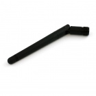
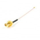
To power and program the board, you'll need a micro-B USB cable and a computer with Arduino installed. To boost your LoRa radio's signal, you'll also need an antenna. You can either use the included U.FL connector -- with a U.FL-to-SMA adapter and 900 MHz SMA antenna -- or solder on a ~3-inch strip of wire.
Tools
You will need a soldering iron, solder, and general soldering accessories.
Weller WLC100 Soldering Station
TOL-14228Suggested Reading
If you aren’t familiar with the following concepts, we recommend checking out these tutorials before continuing.
How to Solder: Through-Hole Soldering
Installing Arduino IDE
Serial Basic Hookup Guide
Hardware Setup
The ESP32 LoRa 1-CH Gateway includes almost everything you need to set up either a LoRaWAN gateway or device. You may not even have to solder anything to it to get started! Here's a quick rundown of the bare minimum you'll need to get started with the board.
Antenna
To allow the board to communicate with other LoRa devices, you'll need to add an antenna. This can be attached to either the U.FL connector or the ANT pin on the board.
The U.FL connector can be attached to an SMA to U.FL adapter cable, which can then be paired with a 900 MHz Duck Antenna.
In lieu of a U.FL antenna, a strip of wire soldered to the ANT pin and sticking straight up will work as well. Here are wire lengths for quarter-wave antennas at 915MHz and 434MHz:
| Frequency | Length (inches) | Length (mm) |
| 915 MHz | 3.07" (3 + 1/16") | 78mm |
| 434 MHz | 6.47" (6 + 1/2") | 164mm |
Powering the Board
The board is nominally powered via the on-board micro-USB connector. The other end of your USB cable can be plugged into either a computer, wall adapter, or a USB battery pack.
Alternatively, the board can be powered using a regulated 3.3V power supply. This supply should be applied to the 3.3V and GND pins.
Arduino IDE Setup
To set up the gateway software you'll need to install the ESP32 Arduino core as well as the library dependencies of the ESP32 LoRa Gateway sketch.
Arduino Board Setup
The example code and libraries for this board are all written for the Arduino IDE. If you haven't already done so, you'll need to install the Arduino core for ESP32. The ESP32 Arduino core must be installed manually. You can find the core files on espressif's GitHub: https://github.com/espressif/arduino-esp32. Follow the Installation Instructions to add the core to your Arduino IDE.
Adding a Custom Board
Although it's possible to upload code to the board using the standard board definitions, we recommend customizing the core to add support for the SparkX ESP32 LoRa Gateway.
To add the custom board, begin by downloading the board's variant file here below.
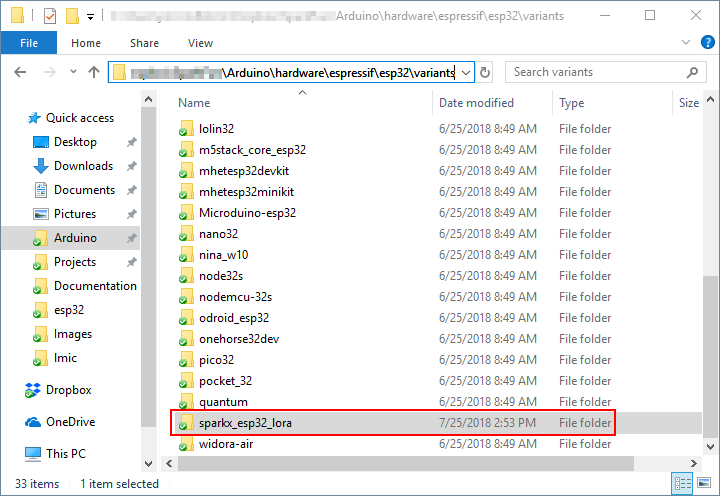
Then unzip the contents into ...{Arduino Sketchbook}/hardware/espressif/esp32/variants.
Next, copy the text below and add it to the bottom of ...{Arduino Sketchbook}/hardware/espressif/esp32/boards.txt:
language:c
##############################################################

sparkx_esp32_lora.name=SparkX ESP32 LoRa Gateway

sparkx_esp32_lora.upload.tool=esptool
sparkx_esp32_lora.upload.maximum_size=1310720
sparkx_esp32_lora.upload.maximum_data_size=294912
sparkx_esp32_lora.upload.wait_for_upload_port=true

sparkx_esp32_lora.serial.disableDTR=true
sparkx_esp32_lora.serial.disableRTS=true

sparkx_esp32_lora.build.mcu=esp32
sparkx_esp32_lora.build.core=esp32
sparkx_esp32_lora.build.variant=sparkx_esp32_lora
sparkx_esp32_lora.build.board=ESP32_DEV

sparkx_esp32_lora.build.f_cpu=240000000L
sparkx_esp32_lora.build.flash_size=4MB
sparkx_esp32_lora.build.flash_freq=40m
sparkx_esp32_lora.build.flash_mode=dio
sparkx_esp32_lora.build.boot=dio
sparkx_esp32_lora.build.partitions=default

sparkx_esp32_lora.menu.PartitionScheme.default=Default
sparkx_esp32_lora.menu.PartitionScheme.default.build.partitions=default
sparkx_esp32_lora.menu.PartitionScheme.minimal=Minimal (2MB FLASH)
sparkx_esp32_lora.menu.PartitionScheme.minimal.build.partitions=minimal
sparkx_esp32_lora.menu.PartitionScheme.no_ota=No OTA (Large APP)
sparkx_esp32_lora.menu.PartitionScheme.no_ota.build.partitions=no_ota
sparkx_esp32_lora.menu.PartitionScheme.no_ota.upload.maximum_size=2097152
sparkx_esp32_lora.menu.PartitionScheme.min_spiffs=Minimal SPIFFS (Large APPS with OTA)
sparkx_esp32_lora.menu.PartitionScheme.min_spiffs.build.partitions=min_spiffs
sparkx_esp32_lora.menu.PartitionScheme.min_spiffs.upload.maximum_size=1966080

sparkx_esp32_lora.menu.FlashMode.qio=QIO
sparkx_esp32_lora.menu.FlashMode.qio.build.flash_mode=dio
sparkx_esp32_lora.menu.FlashMode.qio.build.boot=qio
sparkx_esp32_lora.menu.FlashMode.dio=DIO
sparkx_esp32_lora.menu.FlashMode.dio.build.flash_mode=dio
sparkx_esp32_lora.menu.FlashMode.dio.build.boot=dio
sparkx_esp32_lora.menu.FlashMode.qout=QOUT
sparkx_esp32_lora.menu.FlashMode.qout.build.flash_mode=dout
sparkx_esp32_lora.menu.FlashMode.qout.build.boot=qout
sparkx_esp32_lora.menu.FlashMode.dout=DOUT
sparkx_esp32_lora.menu.FlashMode.dout.build.flash_mode=dout
sparkx_esp32_lora.menu.FlashMode.dout.build.boot=dout

sparkx_esp32_lora.menu.FlashFreq.80=80MHz
sparkx_esp32_lora.menu.FlashFreq.80.build.flash_freq=80m
sparkx_esp32_lora.menu.FlashFreq.40=40MHz
sparkx_esp32_lora.menu.FlashFreq.40.build.flash_freq=40m

sparkx_esp32_lora.menu.FlashSize.4M=4MB (32Mb)
sparkx_esp32_lora.menu.FlashSize.4M.build.flash_size=4MB

sparkx_esp32_lora.menu.UploadSpeed.921600=921600
sparkx_esp32_lora.menu.UploadSpeed.921600.upload.speed=921600
sparkx_esp32_lora.menu.UploadSpeed.115200=115200
sparkx_esp32_lora.menu.UploadSpeed.115200.upload.speed=115200
sparkx_esp32_lora.menu.UploadSpeed.256000.windows=256000
sparkx_esp32_lora.menu.UploadSpeed.256000.upload.speed=256000
sparkx_esp32_lora.menu.UploadSpeed.230400.windows.upload.speed=256000
sparkx_esp32_lora.menu.UploadSpeed.230400=230400
sparkx_esp32_lora.menu.UploadSpeed.230400.upload.speed=230400
sparkx_esp32_lora.menu.UploadSpeed.460800.linux=460800
sparkx_esp32_lora.menu.UploadSpeed.460800.macosx=460800
sparkx_esp32_lora.menu.UploadSpeed.460800.upload.speed=460800
sparkx_esp32_lora.menu.UploadSpeed.512000.windows=512000
sparkx_esp32_lora.menu.UploadSpeed.512000.upload.speed=512000

sparkx_esp32_lora.menu.DebugLevel.none=None
sparkx_esp32_lora.menu.DebugLevel.none.build.code_debug=0
sparkx_esp32_lora.menu.DebugLevel.error=Error
sparkx_esp32_lora.menu.DebugLevel.error.build.code_debug=1
sparkx_esp32_lora.menu.DebugLevel.warn=Warn
sparkx_esp32_lora.menu.DebugLevel.warn.build.code_debug=2
sparkx_esp32_lora.menu.DebugLevel.info=Info
sparkx_esp32_lora.menu.DebugLevel.info.build.code_debug=3
sparkx_esp32_lora.menu.DebugLevel.debug=Debug
sparkx_esp32_lora.menu.DebugLevel.debug.build.code_debug=4
sparkx_esp32_lora.menu.DebugLevel.verbose=Verbose
sparkx_esp32_lora.menu.DebugLevel.verbose.build.code_debug=5
This custom board file specifies the SPI and built-in LED pins. Without it, you'll need to re-define them in your sketch.
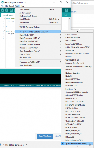
Once the custom board has been added to the ESP32 core, open Arduino and select "SparkX ESP32 LoRa Gateway" under the Tools > Board > ESP32 Arduino menu.
Single-Channel LoRaWAN Gateway Code
The ESP32 single-channel gateway example code is hosted by things4u on GitHub. Download it from their repository.
This repository includes both the Arduino sketch and the libraries it depends on. Before compiling the sketch you'll need to extract all libraries from the repository's "library" folder into your Arduino sketchbook's "libraries" folder. For more help installing the libraries, check out the Getting Started section of the README.
To open the example code, open the ESP-sc-gway.ino file. When the IDE loads, it should include another dozen-or-so tabs -- it's a hefty, but well-segmented sketch!
Configure the Gateway Sketch
Before uploading the ESP-1ch-Gateway sketch to your board, you'll need to make a handful of modifications to a couple of files. Here's a quick overview:
ESP-sc-gway.h
This file is the main source of configuration for the gateway sketch. The definitions you'll probably have to modify are:
- Radio
_LFREQ-- This sets the frequency range your radio will communicate on. Set this to either433(Asia),868(EU), or915(US)_SPREADING-- This sets the LoRa spread factor.SF7,SF8,SF9,SF10,SF11, orSF12can be used. Note that this will affect which devices your gateway can communicate with._CAD-- Channel Activity Detection. If enabled (set to 1) CAD will allow the gateway to monitor messages sent at any spread factor. The tradeoff if enabled: very weak signals may not be picked up by the radio.
- Hardware
OLED-- This board does not include an OLED, set this to 0._PIN_OUT-- This configures the SPI and other hardware settings. Set this to 6, we'll add a custom hardware definition later.CFG_sx1276_radio-- Ensure this is defined and CFG_sx1272_radio is not. This configures the LoRa radio connected to the ESP32.
- The Things Network (TTN)
_TTNSERVER-- The server for your LoRa router. E.g."router.eu.thethings.network"or"us-west.thethings.network"_TTNPORT--1700is the standard port for TTN_DESCRIPTION-- Customize the name of your gateway_EMAIL-- Your email address, or that of the owner of the gateway_LATand _LON-- GPS coordinates of your gateway
- WiFi
- Add at least one WiFi network to the
wpas wpa[]array, but leave the first entry blank. For example:
- Add at least one WiFi network to the
language:c
wpas wpa[] = {
  { "" , "" },                          // Reserved for WiFi Manager
  { "my_wifi_network", "my_wifi_password" }
};
There are a lot of other values which can all optionally be configured. For a complete rundown, check out the Editing the ESP-sc-gway.h part of the README.
loramodem.h
This file defines how the LoRa modem is configured, including which frequency channels it can use and which pins the ESP32 uses to communicate with it. Be careful modifying most of the definitions in here, but one section you will have to modify is the _PIN_OUT declarations.
First, find the line that says #error "Pin Definitions _PIN_OUT must be 1(HALLARD) or 2 (COMRESULT)" and delete it. Then copy and paste these lines in its place (between the #else and #endif):
language:c
struct pins {
  uint8_t dio0 = 26;
  uint8_t dio1 = 33;
  uint8_t dio2 = 32;
  uint8_t ss = 16;
  uint8_t rst = 27; // Reset not used
} pins;
#define SCK  14
#define MISO 12
#define MOSI 13
#define SS  16
#define DIO0 26
The int freqs[] array can be adjusted, if you want to use different subbands, but, beyond that, there's not much else in here we recommend modifying.
Upload the Sketch
With your modifications made, try compiling and uploading the sketch to your ESP32. After it's uploaded, open up your serial monitor and set the baud rate to 115200. Debug messages here can be very handy, and finding your gateway's IP address is critical if you want to monitor the web server.
The sketch may take a long time to set up the first time through -- it will format your SPIFFS file system and create a non-volatile configuration file. Once that's complete, you should see the ESP32 attempt to connect to your WiFi network, then initialize the radio.
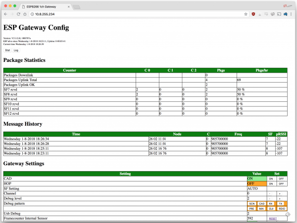
After the ESP32 has connected, look for it to print out an IP address. Open up your computer's web browser and plug that into the address bar. You should be greeted by the ESP Gateway Config web portal:
This web page can be used to monitor messages coming through and what frequencies and spread factors they came in on. It can also be used to change your gateway's configuration on-the-fly. You can adjust the channel or spread factor, or turn CAD on/off, or even turn on simplistic frequency-hopping.
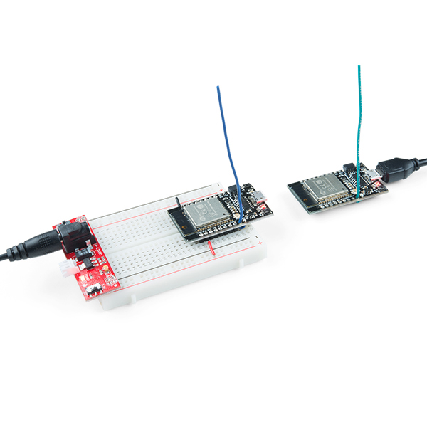
Of course, to see any messages get through you'll need a LoRa device (or device_s_) set up to communicate with your gateway. Check out the next section for a quick guide on setting up a second ESP32 LoRa board as a LoRa device.
Turning a Gateway Into a Device
If you have a pair of ESP32 gateway's you can use one of them as a LoRaWAN device. This section will get you set up with our preferred LoRaWAN Arduino library and a simple example sketch to get started.
Get the Arduino-LMIC Library to Set Up a Device
If you have a pair of ESP32 Gateways and want to set one of them up as a LoRa device, we recommend using the Arduino-LMIC library. There seem to be many versions of the Arduino-LMIC library hanging around, we've had good success with the library forked by mcci-catena:
To install the library, download the ZIP file from GitHub. Then use the Arduino's "Add ZIP library" feature (Sketch > Include Library > Add .ZIP Library) to import the zip file into your Arduino sketchbook.
Configure LMIC
Before can use an example sketch in the LMIC library, you'll need to configure it. To configure the library, navigate to the "arduino-lmic" library in your ..{Arduino Sketchbook}/libraries folder. Then go to project_config and open lmic_project_config.h.
Here you'll define which frequency bands your LoRa device will use. You can also turn on debugging and enable/disable a host of features with definitions in this file.
Make sure you uncomment one-and-only-one of the "CFG..." declarations. If you're in the USA, uncomment #define CFG_us915. Ultimately, this frequency should match what you set in the gateway.
Below is my config file -- I've turned on debugging, because I'm a log junkie.
language:c
// project-specific definitions
//#define CFG_eu868 1
#define CFG_us915 1
//#define CFG_au921 1
//#define CFG_as923 1
// #define LMIC_COUNTRY_CODE LMIC_COUNTRY_CODE_JP   /* for as923-JP */
//#define CFG_in866 1
#define CFG_sx1276_radio 1

//#define LMIC_PRINTF_TO Serial
#define LMIC_DEBUG_LEVEL 2

//#define DISABLE_INVERT_IQ_ON_RX
If you try to use the "raw" example in this library, you'll need to uncomment DISABLE_INVERT_IQ_ON_RX, otherwise keep it commented-out.
Modify the "SPI.begin" call
Just to be sure your pin definitions are correct, I recommend modifying the SPI.begin line in arduino-lmic/src/hal/hal.cpp (line 136 as of this commit) to:
language:c
SPI.begin(14, 12, 13, 16);
This will ensure that your SPI pins are set correctly -- this may only be necessary if you're not using the custom "SparkX ESP32 LoRa Gateway" Arduino board.
Load the Single-Channel Device Example
We've taken one of the examples in the Arduino-LMIC library and modified it to work more reliably with a single-channel gateway.
Click the button below to download the example. Then open up ESP-1CH-TTN-Device-ABP.ino:
Among the modifications in this example are the pin map between radio and ESP32 -- set with these lines:
language:c
const lmic_pinmap lmic_pins = {
  .nss = 16,
  .rxtx = LMIC_UNUSED_PIN,
  .rst = 5,
  .dio = {26, 33, 32},
};
We've also modified the enabled channels to only use a single channel with the lines below (note this modification hasn't yet been tested on non-US frequency bands).
language:c
// First disable all sub-bands
for (int b = 0; b < 8; ++b) {
  LMIC_disableSubBand(b);
}
// Then enable the channel(s) you want to use
LMIC_enableChannel(8); // 903.9 MHz
The spread factor is set near the end of setup() with the LMIC_setDrTxpow(DR_SF7, 14); line. This can be replaced with DR_SF8, DR_SF9, or DR_SF10 at the default 903.9MHz frequency.
But wait! Before uploading this example, there's one more modification you need to make: your LoRaWAN application, network session, and device keys! For that, and an application server, we recommend The Things Network.
Routing to The Things Network
The final components to a LoRaWAN network are a server and application. You can set up a LoRaWAN server of your own, but, for prototyping at least, The Things Network is a great, free tool for authenticating and routing your data.
Single-Channel Blues
At the trade-off of being low-cost, this gateway is only capable of monitoring a single LoRa channel on a limited set of spread factors. Single-channel gateway's don't get much support from LoRaWAN platforms like The Things Network, as they are not, necessarily, LoRaWAN-compliant. They are, however, a great way to begin exploring the world of LoRa and LoRaWAN!
If you haven't already, head to thethingsnetwork.org and create an account. Once that's done, go to your Console.
Create an Application
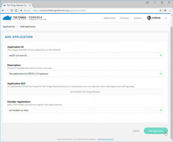
In order to create a device, you first need to create an application to house it under. In the console, click "Applications" then click "add application".
Fill out any ID and description you'd like. The Application EUI will automatically be generated when you create the application. You can also pick your preferred handler for the application (e.g. ttn-handler-us-west).
Create and Configure a Device
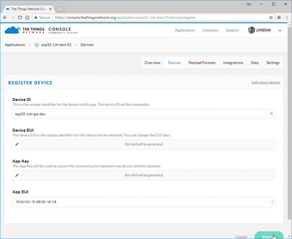
Next create a device in your application. Under the "Devices" section, click "register device".
This is again pretty simple. Fill out a unique device ID, click the "generate" button under "Device EUI" to automatically generate a EUI. Then click "Register."
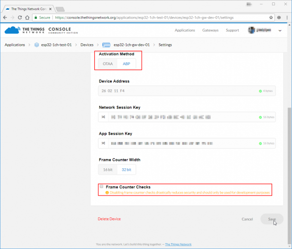
This example sketch only supports ABP activation, so you'll need to modify that in the device settings. In the "Device Overview" page, click "Settings". From there, under "Activation Method" click ABP. I also recommend disabling Frame Counter Checks. The gateway is capable of frame-counter checks, but it can get out of sync -- especially if you have another gateway nearby.
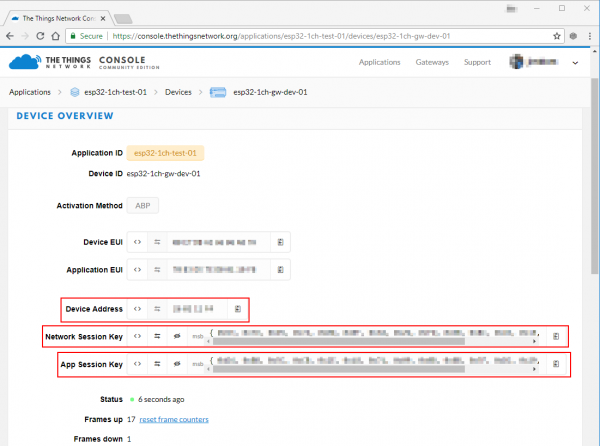
Save the settings and go back to your "Device Overview" page. You should see new keys, including "Network Session Key", "App Session Key", and "Device Address." These will need to be plugged into the device sketch and uploaded to the device.
Update the Example Code
With your application, network session, and device keys in-hand, you're ready to finish configuring the ESP32 LoRa device sketch and start posting data!
On the "Device Overview" page, click the "code" symbol (<>) next to "Network Session Key" and "App Session Key" -- this will make the key visible and display it as a 16-byte array. Copy each of those keys, and paste them in place of the {PASTE KEY HERE} place-holders. "Network Session Key" should be pasted into the NWKSKEY variable and "App Session Key" should be pasted into the APPSKEY variable.
The DEVADDR variable expects a single 32-bit variable, so copy the "Device Address" key as shown and paste that into the PASTE_DEV_ADDR_HERE placeholder.
Here's an example of what your three constants should look like once done:
language:c
// LoRaWAN NwkSKey, network session key
// This is the default Semtech key, which is used by the early prototype TTN
// network.
static const PROGMEM u1_t NWKSKEY[16] = { 0x01, 0x23, 0x45, 0x67, 0x89, 0xAB, 0xCD, 0xEF, 0x01, 0x23, 0x45, 0x67, 0x89, 0xAB, 0xCD, 0xEF };

// LoRaWAN AppSKey, application session key
// This is the default Semtech key, which is used by the early prototype TTN
// network.
static const u1_t PROGMEM APPSKEY[16] = { 0xFE, 0xDC, 0xBA, 0x98, 0x76, 0x54, 0x32, 0x10, 0xFE, 0xDC, 0xBA, 0x98, 0x76, 0x54, 0x32, 0x10 };

// LoRaWAN end-device address (DevAddr)
static const u4_t DEVADDR = 0x01234567;
And that's it! Now upload the code to your ESP32 LoRa board.
Testing the Code
After setup, the device should immediately send a "Hello, World" message. It'll continue to send a message every minute or any time the "0" button on the board is pressed.
To check if your gateway is receiving the message, you can either check the Serial Monitor or monitor the ESP Gateway Config page served by the gateway. Every time a message is received it should be added to the "Message History" table.
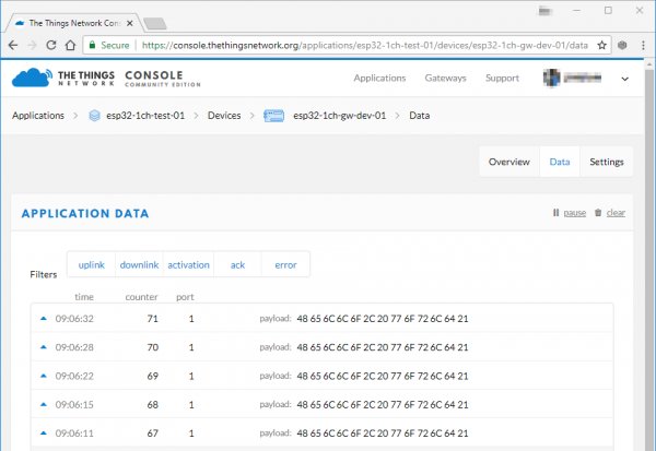
If messages are getting through to your gateway, click the "Data" tab on your device to check for new messages.
The message's payload -- which was encrypted between leaving the device and getting to the router -- should be a series of hex values adding up to "Hello, world".
Troubleshooting
If messages are not getting to your gateway, first make sure the channel and spread factor match up. Left unchanged, the device example code should be sending data out on the 903.9MHz channel at a spread factor of 7 (That's assuming you've set the LMIC library to CFG_us915. If it's set to a European frequency spectrum, it'll be 868.1MHz, SF7).
You can use the gateway's web server to adjust these setting on the fly. Note that the channel numbers should sequentially match the freqs array in loraModem.h -- e.g. channel 0 should be 903.9MHz (again, assuming US frequencies).
If messages are getting to your gateway, but not showing up on your TTN device console, consider changing the _TTNSERVER variable in "ESP-sc-gway.h". I haven't had success with the us-west router, but "router.eu.thethings.network" has worked perfectly (even in the US).
Resources and Going Further
Thanks for coming on this single-channel LoRaWAN gateway journey with us! Here are a few links and documents that might prove handy as you continue exploring the world of LoRa with this board:
- Product Repository -- GitHub repository where you can find all of our latest hardware and software design files.
- Hardware
- Schematic -- PDF schematic
- Eagle Files -- PCB design files
- ESP32 WROOM Datasheet -- Datasheet for the ESP32 WROOM module
- RFM95W Datasheet -- Datasheet for the RFM95W LoRa radio module
- Software
- ESP-1ch-Gateway-v5.0 -- Single-Channel LoRaWAN Gateway Arduino firmware used in this tutorial.
- Arduino-LMIC library -- LoRaMAC-in-C (LMIC) Arduino library used to create LoRaWAN devices.
- ESP-1CH-TTN-Device-ABP -- Single-channel LoRaWAN device example using the Arduino-LMIC library.
