SparkFun ESP32 DMX to LED Shield
 Englandsaurus
Examples
Example 1 - Controller
Materials
- DMX Cable
- DMX Fixture/Additional DMX to LED Shield
To start, we'll output DMX over the XLR Jack to control a DMX capable peripheral device. We'll map out our channels so they control the peripheral device we'll create in the next example. For the sake of simplicity in this first example, we'll control the color of the entire 8x8 matrix as well as the values of each servo. Go ahead and open File->Examples->SparkFun DMX-.Example1-DMXOutput. Looking at the beginning of the example, we include the SparkFunDMX library and create a SparkFunDMX object called dmx We'll use channels 1, 2, and 3 for hue, saturaion and value, the 4th channel will contain pan, and the 5th will be tilt. These are defined in the preamble of the example to help keep track of which channels are where. If we are using two DMX to LED shields (one as output and one as input) we'll want the channel definitions sections to be identical on both output and input sides
language:c
#include <SparkFunDMX.h>

SparkFunDMX dmx;

//Channel Definitions
#define TOTAL_CHANNELS 5

#define HUE_CHANNEL 1
#define SATURATION_CHANNEL 2
#define VALUE_CHANNEL 3
#define PAN_CHANNEL 4
#define TILT_CHANNEL 5
In our setup() loop we begin our DMX shield in write mode by calling dmx.initWrite(TOTAL_CHANNELS);, which enables XLR output. We can then write to our buffer using dmx.write(int channel, uint8_t value); and then send that out over the XLR jack using dmx.update();. In our void loop() we use a for loop and several if statements to decide what to put in each channel, then send that data out. This is shown below.
language:c
void loop() {
  for (int channel = 1; channel <= TOTAL_CHANNELS; channel++) //We don't (and can't) write to channel 0 as it contains 0x00, the DMX start code
  {
    if (channel == SATURATION_CHANNEL || channel == VALUE_CHANNEL) //Write the same value (190/255) = 74.5% to both saturation and value.
    {
      dmx.write(channel, 190);
    }
    else if (channel == HUE_CHANNEL || channel == PAN_CHANNEL || channel == TILT_CHANNEL) //Sweep across our servos as well as a rainbow cycle.
    {
      dmx.write(channel, x);
    }
  }
  Serial.print(x++);//Print and increment x. Since x is an unsigned 8 bit integer it will loop back to 0 if we try to increment it past 255
  dmx.update(); // update the DMX bus witht he values that we have written
  Serial.println(": updated!");
  delay(100);
}
You can open the Serial Monitor to 115200 baud if you'd like to see the current value being written to hue and the servos, but we won't truly be able to see the output until we connect to a peripheral device.
Example 2 - Peripheral
Materials
- DMX Cable
- DMX Controller/additional DMX to LED Shield
- LED's (Optional)
- Pan/tilt Servo (Optional)
In this example, we'll be creating the world's most adorable moving head light using a LuMini 8x8 Matrix and our Pan/Tilt Servo Kit, although you're totally allowed to use different servos with our other servo mounting kit if you want some nicer servos. What we'll do is set our ESP32 to send our first 3 channels of DMX data to our LED matrix to color it, the 4th and 5th channels will be used to control the servos.
Optional Hardware Assembly
If you're deciding to create a tiny version of a moving head, assemble your pan and tilt servos as well as soldering some wire onto the LuMini Matrix if you haven't already. Attach your LED's to your moving head how you see fit, I've used poster putty to attach mine for this simple demo. Go ahead and connect the data pin (orange on the Pan/Tilt Servo Kit) on your pan servo (left to right) to the D1 poke-home connector and the tilt servo to the D2 poke-home. Connect D0 and C0 to DI and CI on whatever APA102/LuMini LED's you've decided to use. If you're using WS2812 type LED's, you'll only need to connect your DATA line to D0. My setup is shown below, with the LED lines on the left set of poke-home connectors and the servos on the two right sets.

Peripheral Code
If you haven't already, go ahead and open up File->Examples->SparkFun DMX-.Example2-DMXInput. On our peripheral side, we'll want to make sure that our channel definitions in our preamble match those in our output example, as we'll need to know how many channels we'll be receiving and what to do with each part of the data. We'll then need to declare our hardware for our custom DMX fixture, in this case two servos and a matrix of LED's. All of the definitions are shown below.
language:c
//Channel Defintions
#define TOTAL_CHANNELS 5

#define HUE_CHANNEL 1
#define SATURATION_CHANNEL 2
#define VALUE_CHANNEL 3
#define PAN_CHANNEL 4
#define TILT_CHANNEL 5

//Fixture Hardware Definitinos
#define NUM_LEDS 64
CRGB matrix[NUM_LEDS];
Servo pan;
Servo tilt;
In our setup() loop we initialize our LEDs and servos as well as put our shield in read mode by calling dmx.initRead(totalChannels);.
language:c
void setup()
{
  Serial.begin(115200);
  dmx.initRead(TOTAL_CHANNELS);           // initialization for complete bus
  Serial.println("initialized...");

  FastLED.addLeds<APA102, DATA0, CLOCK, BGR>(matrix, NUM_LEDS);
  FastLED.setBrightness(16);
  pan.attach(DATA1);
  tilt.attach(DATA2);
}
We can then call dmx.update(); to update our data buffer, which we can then access by calling dmx.read(int channel);. We use this process to read our data from the corresponding channels into the proper hardware peripherals in the void loop().
language:c
void loop()
{
  dmx.update();
  for (int led = 0; led < NUM_LEDS; led++)
  {
    matrix[led] = CHSV(dmx.read(HUE_CHANNEL), dmx.read(SATURATION_CHANNEL), dmx.read(VALUE_CHANNEL));
  }
  pan.write(map(dmx.read(PAN_CHANNEL), 0, 255, 0, 160));
  tilt.write(map(dmx.read(TILT_CHANNEL), 0, 255, 0, 160));
  FastLED.show();
}
Loading example 1 up to one shield and example 2 up to another and connecting them via XLR should yield an output similar to the below GIF.
Example 3 - ArtNet Input
Materials
- LED's (Optional)
- Pan/tilt Servo (Optional)
Arduino Code
This example is quite similar to the previous peripheral example, except this time we will be receiving ArtNet data over WiFi from Resolume Arena 6, a popular video jockey software. Let's begin by setting up our ArtNet Input, we'll be taking our hardware setup from the previous example and leveraging it here, so all of the definitions for the hardware peripherals will remain the same. However, in this example, we'll be controlling each LED on our matrix individually, so we'll use 192 (64 LED's multiplied by 3 channels per LED) channels for LED's instead of 3. This makes our Channel definition section look like the below.
language:c
//Channel and Peripheral Definitions
#define NUM_LEDS 64
#define NUM_LED_CHANNELS NUM_LEDS * 3 //Ends up being 192 channels for our 8x8 LED matrix
#define PAN_CHANNEL 193
#define TILT_CHANNEL 194
CRGB matrix[NUM_LEDS];
Servo pan;
Servo tilt;
We then need to begin WiFi and ArtNet. The example defaults to using the ESP32 as a standalone access point but you can change lines 23, 24, 54, 55 and 57 if you'd like to connect to an existing network. If not however, the standalone access point will have an SSID of myDMX and the password will be artnetnode. We then initialize our artnet object (which we created in the preamble with ArtnetWifi artnet;) with artnet.begin(); which will begin scouring the network for Artnet packets. We then use artnet.setArtDMXCallback(onDmxFrame); so that onDmxFrame is called each time we see an Artnet packet on the network. onDmxframe is the function that we will be changing based on our setup to parse data into the proper hardware attachments. We loop through all of our channels and place them into the proper segments using if statements. This code is outlined below.
language:c
void onDmxFrame(uint16_t universe, uint16_t length, uint8_t sequence, uint8_t* data)
{
  // read universe and put into the right part of the display buffer
  //DMX data should be sent with the first LED in the string on channel 0 of Universe 0
  for (int channel = 0; channel < length; channel++)
  {
    if (channel < NUM_LED_CHANNELS && channel % 3 == 0) //Only write on every 3rd piece of data so we correctly parse things into our RGB array
    {
      matrix[channel / 3] = CRGB(data[channel], data[channel + 1], data[channel + 2]);
    }
    else if (channel == PAN_CHANNEL - 1) //Subtract 1 due to the fact that we index at 0 and ignore the startcode
    {
      pan.write(map(data[channel], 0, 255, 0, 160));
    }
    else if (channel == TILT_CHANNEL - 1)
    {
      tilt.write(map(data[channel], 0, 255, 0, 160));
    }
  }
  previousDataLength = length;
  if (universe == endUniverse) //Display our data if we have received all of our universes, prevents incomplete frames when more universes are concerned.
  {
    FastLED.show();
  }
}
Resolume Setup
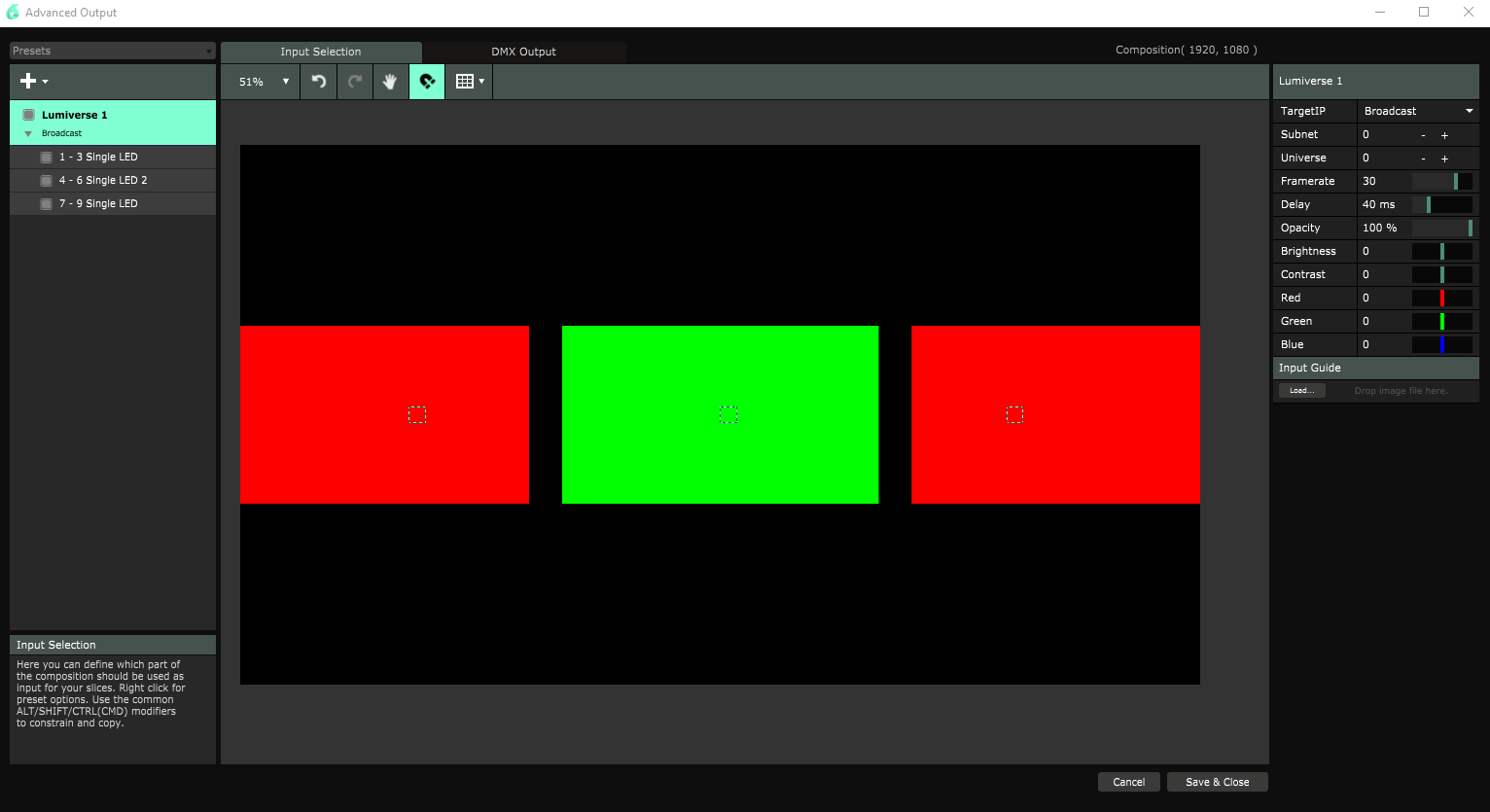
If you haven't yet, go check out the ArtNet DMX and ESP32 Pixel Pushing Guide for some help setting up custom fixtures in Resolume. You'll need to create two fixtures, one for your 8x8 display, and a single channel fixture to control pan and tilt. Then, create a Lumiverse with your 8x8 matrix in the center and the two fixtures; one for pan and one for tilt in each corner. Also ensure that you change TargetIP to IPAddress and change the address to 192.168.4.1 to send data directly to your ESP32.
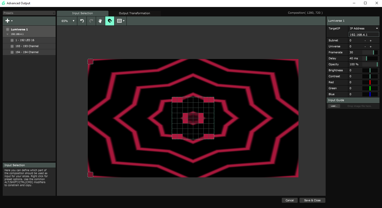
We'll then downsize our main video source so it isn't taking up the corners of the display and affecting the inputs for the pan and tilt channels. We'll then add two solid color blocks in the corners so we can affect the pan and tilt channels of our fixture. This is a very hacky way to do things, but Resolume is meant for video screens and not full fledged fixtures. We will then modulate the brightness of our solid color blocks in order to send data to the corresponding DMX channels. You can set all this up yourself, or download the composition below.
Connecting to the same network as the ESP32 will send data to your screens and servos. Check out the below gif to see what should be going on if you've set everything up correctly.
Example 4 - ArtNet to XLR
Materials
- DMX Cable
- DMX Fixture
This final example will combine everything we've learned so far to control a non ArtNet capable peripheral over ArtNet. Our Controller board will be turning Artnet data into DMX output. Our main change here will be that we change our onDmxFrame function to write our incoming Artnet data to our XLR buffer. This is accomplished with a simple for loop, shown below.
language:c
void onDmxFrame(uint16_t universe, uint16_t length, uint8_t sequence, uint8_t* data)
{
  sendFrame = 1;
  //Read universe and put into the right part of the display buffer
  //DMX data should be sent with the first LED in the string on channel 0 of Universe 0
  for (int channel = 0; channel < length; channel++)
  {
    dmx.write(channel, data[channel]);
  }
  previousDataLength = length;
  if (universe == endUniverse) //Display our data if we have received all of our universes, prevents incomplete frames when more universes are concerned.
  {
    dmx.update();
  }
}
I have a non Artnet capable fixture laying around; an old Casa laser. I did some digging round on the internet to find this slot map. I then mapped out channels in Resolume to match up with the 7 channels available on the laser. To do this, I simply created three separate solid colors and placed an LED on each one. This makes my red value on my first led channel one, green channel 2, and so on. The second LED is channels 4-6 and sits on the second color. This is shown in the below image.
With all of these and my fixture map, I am able to send the data I want over to the laser over WiFi. The below clip consists of simply moving some channels around at random and watching the output.