SparkFun ESP32 DMX to LED Shield
 Englandsaurus
Hardware Overview
Power
You should always power the DMX shield with 5V to provide proper power for RS485. The DMX to LED shield can be powered through either the screw terminals or the USB connection on your microcontroller that is plugged into the shield.
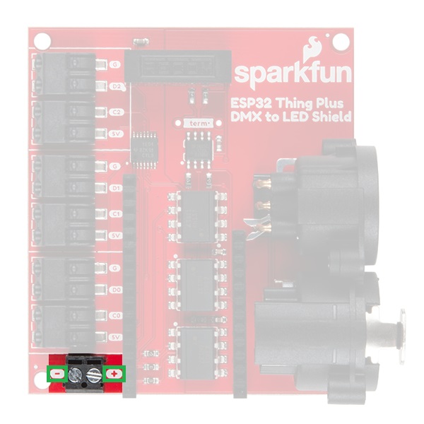
Power Screw Terminal
For applications with high current draw be sure to use the available screw terminals to provide power. If you are powering a large LED array or many servos, you may start seeing power dips due to your USB power supply's inability to give enough current. The screw terminal is a 2-pin 3.5 mm screw terminal that should be able to accept 26-16 AWG wire with a strip length of ~5-6 mm. The screws are M2 screws, so you will probably need a smaller jewelry size screw driver.
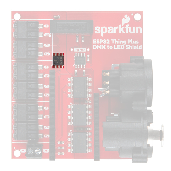
Logic Level Converter
Since many Feather boards are 3.3V logic, there is a logic level converter between the microcontroller and LED data pins to bring the poke-home connectors up to 5V logic.
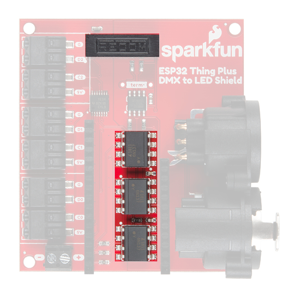
Power and Data Isolation
As per DMX spec, microcontroller power should be electrically isolated from XLR communication. This has been accomplished with a DC-DC converter and optoisolators. The DC-DC converter has an isolation voltage of 1 kVDC (rated to 1 min.) and isolation resistance of 1 GΩ. The DC-DC converter outputs 200 mA at 5V and can take a surge voltage of 9 VDC (for 100 μs).
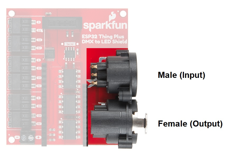
XLR Connectors
XLR cables are commonly used in the stage lighting and sound industry. Each DMX to LED Shield has a 3-pin (aka XLR-3) male and female XLR connector. When using these, be very careful NOT to plug into any audio equipment as you will likely damage your DMX to LED Shield. To remove a cable, just press down on the button on the cable or connector and pull it out. Typically, the male XLR connector on the peripheral is the input while the female is the output.
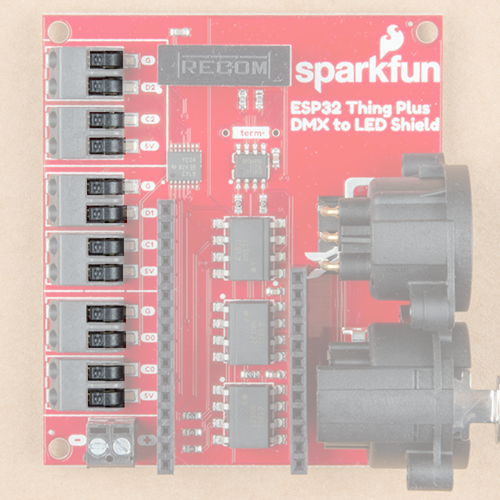
Poke Home Connectors
The outputs for the poke home connectors are laid out to match up with APA102 LED strips and LuMini devices.
Due to this, all of the clock lines have been connected to the same output on the ESP32 (or whatever microcontroller you happen to be using). The pins on the shield have been labeled with the corresponding poke home connectors in the image below, so you know which pins to connect to if you want to use them for other purposes.
| ESP32 Thing Plus | DMX Shield |
| SCK |
CO C1 C2 |
| COPI | D0 |
| CIPO | D1 |
| Pin 27 | D2 |
To use the poke-home connector, simply press down on the tab with a ballpoint pen (a key or screwdriver also works well) while pushing in the wire. The tabs to depress are highlighted in the image below, be aware that it'll take some extra finesse to get stranded core wire into these connectors. These connections should be able to accept **24-18 AWG** wire.
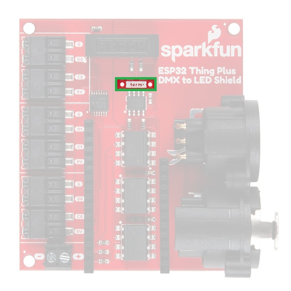
Termination Resistor Pad
A pad for a 120 Ω termination resistor is broken out on the shield. This is used to help increase the signal reflection, if the shield is at the end of a chain of DMX devices. If you don't have a 120 Ω resistor, a 100 Ω resistor can be used.