Using Artnet DMX and the ESP32 to Drive Pixels
 Englandsaurus
Introduction
I like to make things glow probably far more than a colorblind person should, and I've been looking for new and interesting ways to control the output of different lighting applications without having to hard-code in different color sequences. I'd like to be able to have some sort of complex visual, and then have that be able to play on the lights without having to think about which LED needs to be which color in a display.
Required Materials
To follow along with this project tutorial, you will need the following materials:
Please note that although the WS2812 are 5V LED's, you can usually get away with driving small numbers on only 3.3V logic, so I'm going to skip the logic translation as this tutorial is mainly about DMX. You'll also need some 20AWG wire to connect the LED strip to your breadboard.
Tools
The following tools are required to follow along with this tutorial:
- Soldering Iron
- Solder
- Flux
- Breadboard
- Power supply
- Optional Fixed Voltage Power Supply (If you are going to create an actual LED installation, you'll need a dedicated power supply)
Suggested Reading
If you aren’t familiar with the following concepts, we recommend checking out these tutorial before continuing.
WS2812 Breakout Hookup Guide
ESP32 Thing Hookup Guide
Introduction to DMX
Hardware Assembly
In order to connect our ESP32 to our lights, we'll first need to solder headers onto the ESP32. If you haven't soldered headers onto anything before, check out our through-hole soldering tutorial. Once you have headers soldered on, the circuit is relatively simple.
To set up the circuit, connect your LED strips together using the connectors attached to the strips, then connect the strip to 5V (supplied by an external power supply) and ground. The ESP32 can also be powered from 5V using either of the VUSB pins. Also be sure that the ground of the LED strips and the ground of the ESP32 are connected to avoid noise on the LED strips. Connect the data pin of your LED strip to pin 12 of the ESP32. Power the ESP32 by USB, as we will eventually be using serial communication to talk to the ESP32. I was having some issues with brownouts, so I added 2 1 mF capacitors. If you're confused on the layout, check out the below Fritzing diagram.
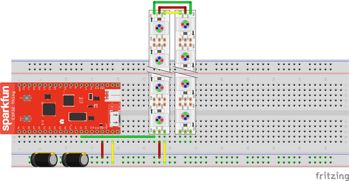
Now that our circuit is ready to go, let's lay out our pixel strips parallel to each other, about 5/8" apart (this is the spacing between pixels on the strips, so spacing our strips like this will mean that each pixel is equidistant to each of its neighbors, creating a consistent pixel density). Ensure that data flows into the top left of the pixel array, left to right across the top strip, then down to the bottom strip, and across the bottom strip from right to left.
Creating an ArtNet Node on the ESP32
We now have to get our ESP32 to listen for DMX data on the WiFi network. In order to do this, we'll first need to setup the ESP32 Core on the Arduino IDE. In order to do this, head over to that section of the ESP32 Hookup Guide.
Note: This example assumes you are using the latest version of the Arduino IDE on your desktop. If this is your first time using Arduino, please review our tutorial on installing the Arduino IDE. If you have not previously installed an Arduino library, please check out our installation guide.
Once we have this set up we'll need to download the ArtNet WiFi library along with a branch of the FastLED library that plays nicely with the ESP32. These libraries are downloadable below.
Once we have our libraries installed, load the following example code (which was adapted from the ArtNet Neopixel example contained within the library) into your ESP32. Explanations for subroutines are found within the comment of the code.
language:c
#include <WiFi.h>
#include <WiFiUdp.h>
#include <ArtnetWifi.h>
#include <FastLED.h>

//Wifi settings - be sure to replace these with the WiFi network that your computer is connected to

const char* ssid = "SSID";
const char* password = "pAsSwOrD";

// LED Strip
const int numLeds = 120; // Change if your setup has more or less LED's
const int numberOfChannels = numLeds * 3; // Total number of DMX channels you want to receive (1 led = 3 channels)
#define DATA_PIN 12 //The data pin that the WS2812 strips are connected to.
CRGB leds[numLeds];

// Artnet settings
ArtnetWifi artnet;
const int startUniverse = 0;

bool sendFrame = 1;
int previousDataLength = 0;

// connect to wifi – returns true if successful or false if not
boolean ConnectWifi(void)
{
  boolean state = true;
  int i = 0;

  WiFi.begin(ssid, password);
  Serial.println("");
  Serial.println("Connecting to WiFi");

  // Wait for connection
  Serial.print("Connecting");
  while (WiFi.status() != WL_CONNECTED) {
    delay(500);
    Serial.print(".");
    if (i > 20){
      state = false;
      break;
    }
    i++;
  }
  if (state){
    Serial.println("");
    Serial.print("Connected to ");
    Serial.println(ssid);
    Serial.print("IP address: ");
    Serial.println(WiFi.localIP());
  } else {
    Serial.println("");
    Serial.println("Connection failed.");
  }

  return state;
}

void onDmxFrame(uint16_t universe, uint16_t length, uint8_t sequence, uint8_t* data)
{
  sendFrame = 1;
  // set brightness of the whole strip
  if (universe == 15)
  {
    FastLED.setBrightness(data[0]);
  }
  // read universe and put into the right part of the display buffer
  for (int i = 0; i < length / 3; i++)
  {
    int led = i + (universe - startUniverse) * (previousDataLength / 3);
    if (led < numLeds)
    {
      leds[led] = CRGB(data[i * 3], data[i * 3 + 1], data[i * 3 + 2]);
    }
  }
  previousDataLength = length;
  FastLED.show();
}

void setup()
{
  Serial.begin(115200);
  ConnectWifi();
  artnet.begin();
  FastLED.addLeds<WS2812, DATA_PIN, GRB>(leds, numLeds);

  // onDmxFrame will execute every time a packet is received by the ESP32
  artnet.setArtDmxCallback(onDmxFrame);
}

void loop()
{
  // we call the read function inside the loop
  artnet.read();
}
With this code loaded into the ESP32, go ahead and open your serial monitor to 115200 baud and check that the ESP32 is connecting to WiFi. Once it is, make note of the IP address shown in the Serial monitor.

DMX - No, not the rapper!
Before we start controlling lights, let's learn a little bit about how DMX works. DMX512 is a standard digital communication ecosystem typically used for stage lighting. It is primarily used to link lighting controllers to dimmable lights, fog, moving projectors and my personal favorite, laser beams. The hardware and data structure used to interface between DMX controllers and fixtures can be changed to fit the various applications of DMX.
Hardware
DMX fixtures can employ multiple hardware solutions for communication. The most common of these is the XLR 5-pin connector. However, you can also use an RJ-45 connector to send DMX data. Both cabling solutions take advantage of differential signaling using EIA-485 Voltage Levels. Wikipedia has a great summary of various DMX cable pinouts. For the purposes of my experiment, I'm sending data to a WiFi enabled DMX fixture, so I'll need neither of these cables.
Data Protocol
A DMX512 network, or DMX Universe can be comprised of many separate DMX fixtures (Fog machines, intelligent lights, etc...) all daisy chained together. The DMX controller will send a frame of data down this line. This frame consists of a break and subsequent mark to signal that a new frame has begun. The controller then sends out slot 0, which contains a one byte start code. Once all of the fixtures in our DMX Universe see this, the controller sends 512 slots of data (called channels), each containing a byte. To create an RGB color, a channel is required for red, green, and blue. This means that the number of individually addressable pixels that can be controlled in a single DMX Universe is 170.
Resolume Setup
If you haven't already, go ahead and download and install Resolume Arena 6. Once we have this installed, we'll have to do some set up to create objects to represent our pixel strips. When dealing with custom-made DMX fixtures, you'll need to create a unique fixture so Resolume knows where your pixels are in Cartesian space. For this experiment, I'm going to create a unique lighting fixture in Resolume to represent a lighting strip, and then set up two of these custom fixtures (one to represent each LED strip) in a "Lumiverse"; Resolume's fancy word for a DMX Universe.
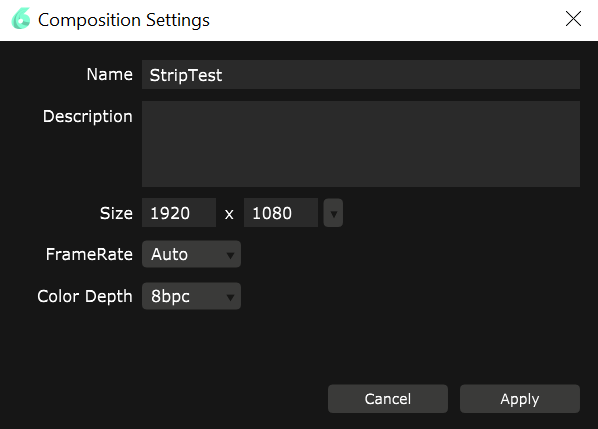
Before we begin, let's change our composition to full HD by going to Composition>Settings... and changing the width to 1920 and the height to 1080. Give your composition a name and also ensure that you have 8bpc color depth.
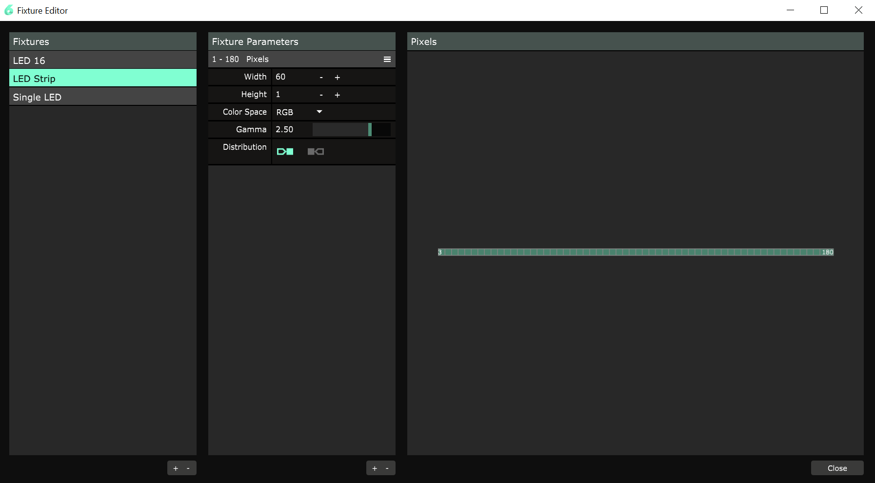
Create a Fixture
To get started creating a custom fixture, go to Application>Fixture Editor.... Once in this window go ahead and add a new fixture in the far left column, I'm calling mine LED Strip because, well, that's what it is. Once you've added your fixture, you should see a single pixel in the window on the right. This is because we currently have a 1 wide, 1 tall, pixel array. The 1 M LED Strip has 60 LED's on it, so we'll go ahead and change our width to 60 and look, we've got something to represent our LED strip.
Create a Lumiverse
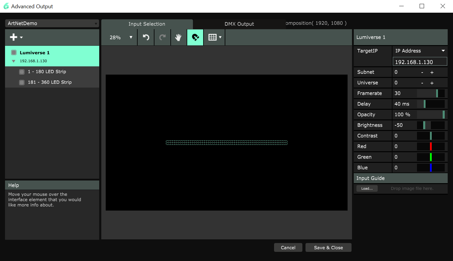
Now we need to set up our strips in a single Lumiverse. To do this, go to Output>Advanced... and create a new preset. This preset should default to having a Screen with a Slice in it. We've got to get rid of this, but Resolume won't allow you to have nothing in your output, so we'll have to hit the big + button and add a Lumiverse. Once we've done this, we'll be able to get rid of the extra Screen and Slice. We now need to add our LED Strips into the Lumiverse. To do this, click on the first fixture in our Lumiverse, this will bring up all of the features of the fixture on the right side of the screen. In the bottom right corner, you will be able to select LED Strip from a dropdown menu, changing the fixture to a 60 LED long strip! Now if we go back to our big + button and add a fixture, Resolume will add another LED strip. Finally change the width of each LED strip to 960 and change the height to 16. Since our LED strips are laid out right next to one another, this is how we should place them in our composition. To do this, set the Y-value of the first LED Strip to 532 and the Y-value of the second LED strip to 548. This will put them right on top of one another. We also know from the way that we hooked our strips together that data flows from left to right on the top strip, and from there it flows into the bottom strip and goes from right to left. Resolume needs to know this, so we must flip our bottom strip 180 degrees in order to make this happen. In the end, your Advanced Output window should look something like the below image.
If you are having some trouble setting up your Advanced Output, you can download the presets here and load it into your Advanced Output. Just make sure that before you try to load the preset, you've dropped the LED Strip fixture into Documents > Resolume Arena 6 > Fixture Library and restarted Resolume so the software knows which fixture to use.
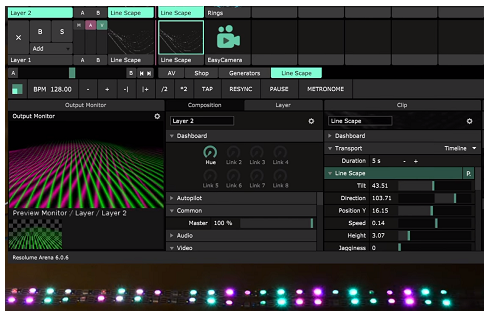
Broadcast
Now that we have a map for our LED's, let's start broadcasting some video to them. First we'll need to snag some video to play. Go to the bottom right corner of Resolume's main window, go to Sources>Generators and pick out something you like. You may then drag it to whatever layer you'd like (I've found that playing around with and stacking line generators looks quite pretty). Double clicking on the video will send it to the output. Now we can reopen our Advanced Output window, select the Lumiverse we just created, and change the TargetIP setting on the right side of the monitor to the IP address we earlier saw the ESP32 give when it connected to WiFi. If your ESP32 is connected to WiFi, you should now be seeing your strips light up along with the media displayed on the output monitor. If you're seeing a little lag, try lowering the frame rate in Advanced Output. You should be able to drive your lights with very little noticeable delay between the Advanced Output and the actual LEDs, just like the below video.
Resources and Going Further
Now that you know how to create your own fixtures, try making some bigger displays of your own and mapping them out in Resolume. Your power supply is the limit!