SparkFun 9DoF IMU (ICM-20948) Breakout Hookup Guide
 Liquid Soulder
Software Setup and Example Code
In this example, we are using the SparkFun Esp32 Thing WROOM Plus. If you have not used this board before, head on over to the ESP32 Thing Plus Hookup Guide for a general overview, as well as information on getting set up with board definitions.
ESP32 Thing Plus Hookup Guide
In order to use the ICM-20948 breakout, you'll need to install the SparkFun ICM-20948 Arduino Library. We recommend you install the library via the Arduino IDE by using the library manager and search for Sparkfun 9DoF IMU Breakout. Or you can download and manually install a zip of the library by clicking on the link below. For those who want to view the code, check out the GitHub repo.
Example 1
In this example, we've hookup up our ICM-20948 to an ESP32 Thing Plus using a short Qwiic cable.
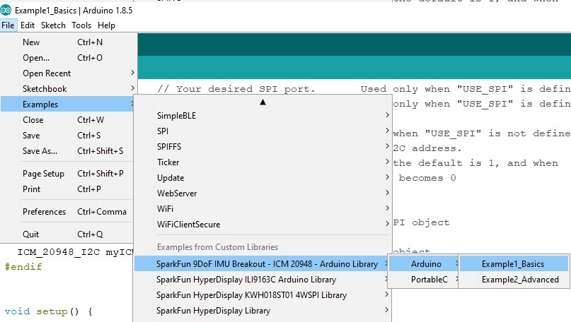
Once you've installed the ICM-20948 library, load the first example sketch from File->Examples->SparkFun 9DoF IMU Breakout - ICM 20948 - Arduino Library->Arduino->Example1_Basics.
The very first thing you'll see in the code is the #include statement for the library. Alongside that is a convenient link that will help you get the library through the Arduino library manager. Next is a commented out #define statement called 'USE_SPI'. If instead you have chosen to connect your ICM with the SPI pins all you need to do is uncomment that line.
language:c
#include "ICM_20948.h"  // Click here to get the library: http://librarymanager/All#SparkFun_ICM_20948_IMU

//#define USE_SPI       // Uncomment this to use SPI
Up next is a short section where you can configure your particular setup. First of all if you need to change your serial port, e.g. if you're using a SAMD21 board, you can change the 'SERIAL_PORT' define ('SerialUSB' for SAMD21). You can do the same to change your I2C port or SPI port, depending on which you're using. When using I2C you have the ability to change the I2C address of the sensor with the Address 0 bit. By default it is '1' but you could change it to 0 if you've closed the 'ADR' jumper. When using SPI you need to specify a chip select pin - in the example we default to pin 2.
language:c
#define SERIAL_PORT Serial

#define SPI_PORT SPI    // Your desired SPI port.       Used only when "USE_SPI" is defined
#define CS_PIN 2        // Which pin you connect CS to. Used only when "USE_SPI" is defined

#define WIRE_PORT Wire  // Your desired Wire port.      Used when "USE_SPI" is not defined
#define AD0_VAL   1     // The value of the last bit of the I2C address.
                        // On the SparkFun 9DoF IMU breakout the default is 1, and when
                        // the ADR jumper is closed the value becomes 0
That's it for stuff you (might) need to do to set up the example! Now we'll just all hop in the bus, take a tour, and I'll point out items on your right and left.
The next little block creates either a ICM_20948_I2C or ICM_20948_SPI object called 'myICM'. Since they have the same name, and they both inherit from the grandaddy ICM_20948 class, we'll be able to use them interchangeably later on in the example.
language:c
#ifdef USE_SPI
  ICM_20948_SPI myICM;  // If using SPI create an ICM_20948_SPI object
#else
  ICM_20948_I2C myICM;  // Otherwise create an ICM_20948_I2C object
#endif
In the setup() function we have your standard Arduino initialization of your serial port, and then we have the last interface-dependent section. There you'll see the 'myICM' object being started up with the appropriate arguments for the chosen interface. This example shows all arguments being explicitly stated, but it is also possible to call the .begin() function with default arguments. The initialization will repeat with a delay until the device is successfully found. If it is not connecting try checking your wiring.
language:c
#ifdef USE_SPI
    SPI_PORT.begin();
    myICM.begin( CS_PIN, SPI_PORT );
#else
    WIRE_PORT.begin();
    WIRE_PORT.setClock(400000);
    myICM.begin( WIRE_PORT, AD0_VAL );
#endif
Here's a little trick for debugging the ICM - nearly all operations will update the internal 'myICM.status' value. You can check it directly (0 means all good, anything else is an error) or you can use the statusString() method to get the latest status in human-readable form.
language:c
    SERIAL_PORT.print( F("Initialization of the sensor returned: ") );
    SERIAL_PORT.println( myICM.statusString() );
    if( myICM.status != ICM_20948_Stat_Ok ){
      SERIAL_PORT.println( "Trying again..." );
      delay(500);
    }else{
      initialized = true;
    }
The last part of the sketch is the loop() where the sensor gets polled for new data, and that data gets pushed over the serial port. All the data is contained in the 'AGMT' structure, which stands for Accelerometer, Gyroscope, Magnetometer, and Temperature sensors. For convenience this sketch also includes functions (that are not part of the library) to print the results in a pretty format.
language:c
void loop() {

  if( myICM.dataReady() ){
    myICM.getAGMT();                // The values are only updated when you call 'getAGMT'
//    printRawAGMT( myICM.agmt );     // Uncomment this to see the raw values, taken directly from the agmt structure
    printScaledAGMT( myICM.agmt);   // This function takes into account the sclae settings from when the measurement was made to calculate the values with units
    delay(30);
  }else{
    Serial.println("Waiting for data");
    delay(500);
  }

}
When you open up your Serial Monitor, you should see something like the following:
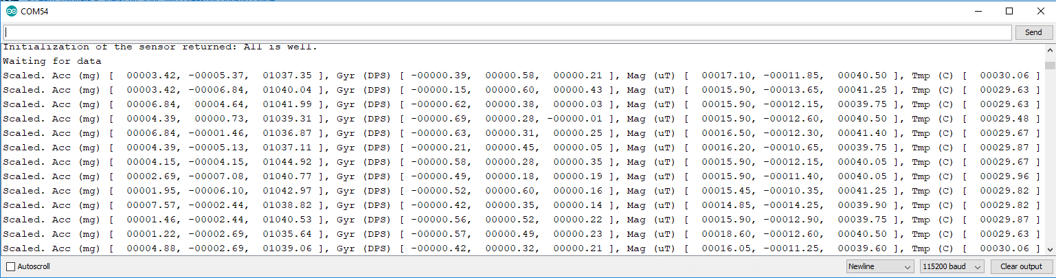
There ya have it! Now go ahead and hack it up.