SparkFun 9DoF IMU (ICM-20948) Breakout Hookup Guide
 Liquid Soulder
Hardware Overview
We've put a lot of effort into making this the most useful and versatile breakout for the ICM 20948. Let's take a closer look at all the special parts.
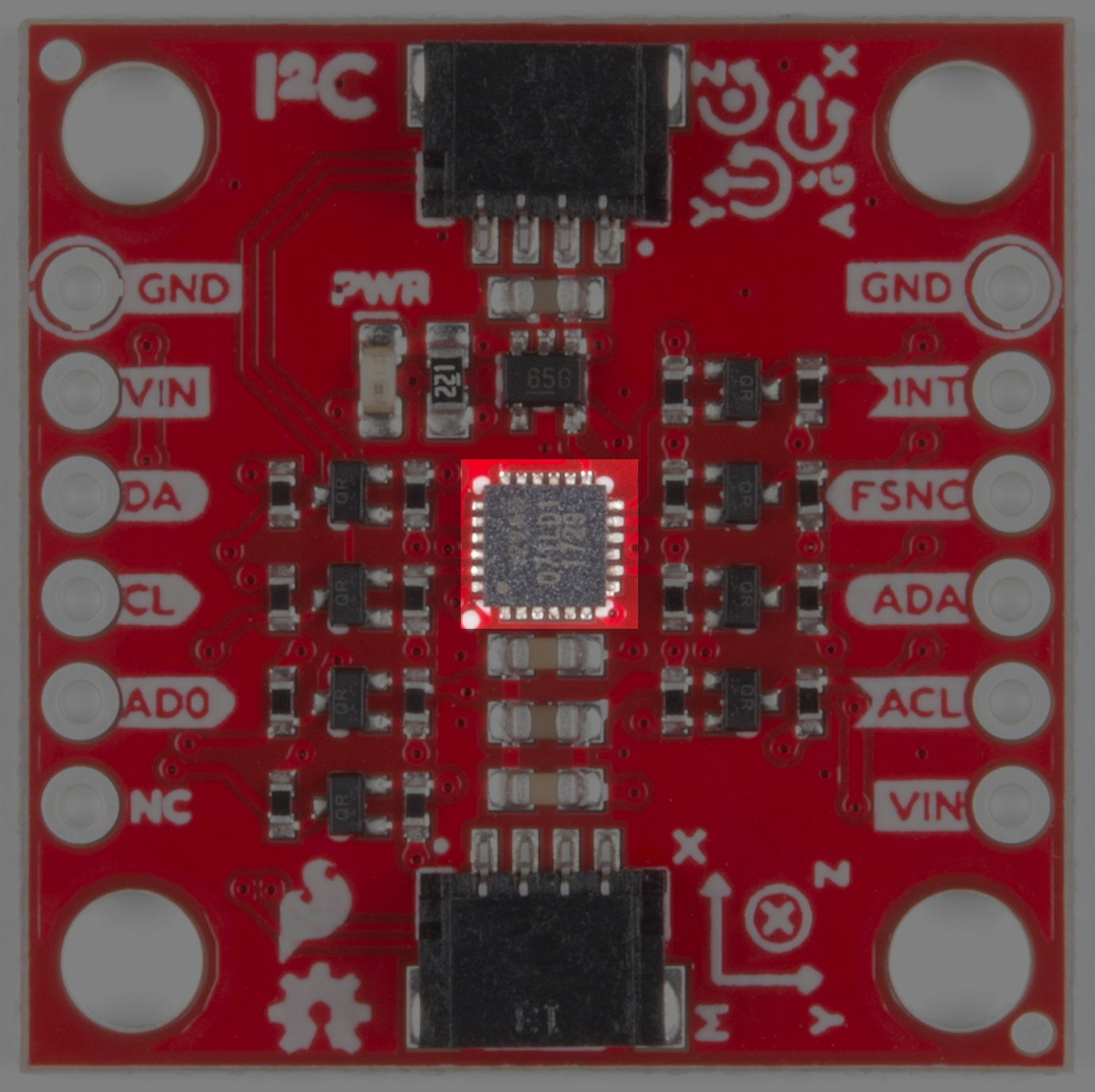
Sensor
At the heart of the board (metaphorically and geometrically) is the ICM 20948 from Invensense. This puppy packs the ability to measure up to 10 unique values (3 axes of acceleration, rotational rate, and magnetic strength data as well as an on-board temperature sensor). The sensor is placed dead-center between the four 4-40 stand-off mounting holes to drastically simplify computation in dynamics.
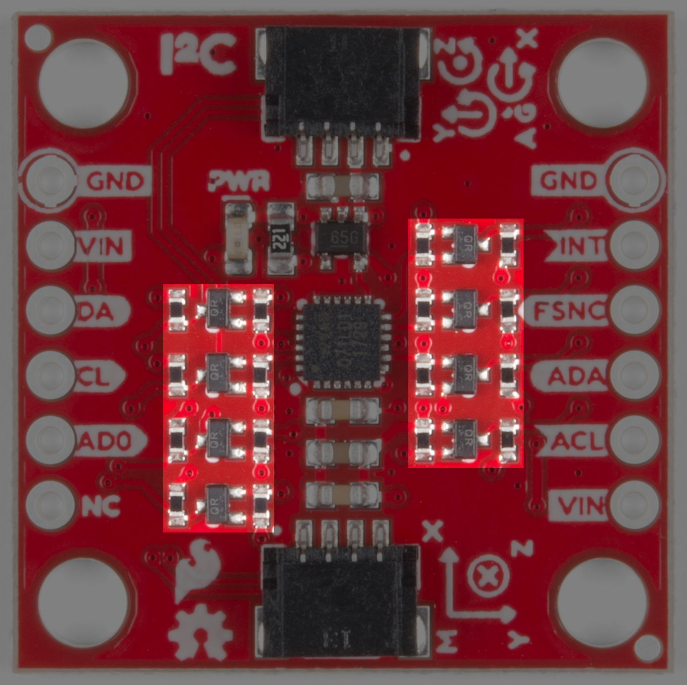
Level Shifters
The ICM is a fickle fellow - optionally allowing a 3.3V supply voltage but requiring I/O to work at 1.8V. This is just the price we pay for amazing technolojay (hey that rhymes). Since there aren't many popular development boards that run at the voltage of the future we've added high speed level shifting to each and every IO pin. These cool MOSFETS allow for bi-directional voltage translation up to the maximum SPI speed of the ICM - 7MHz - which will allow you to make inertial measurements with fantastic temporal resolution. Feel free to use the ICM IO anywhere from 1.8V to 5.5V!
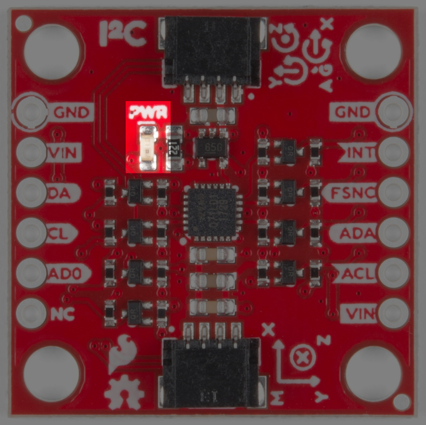
Power
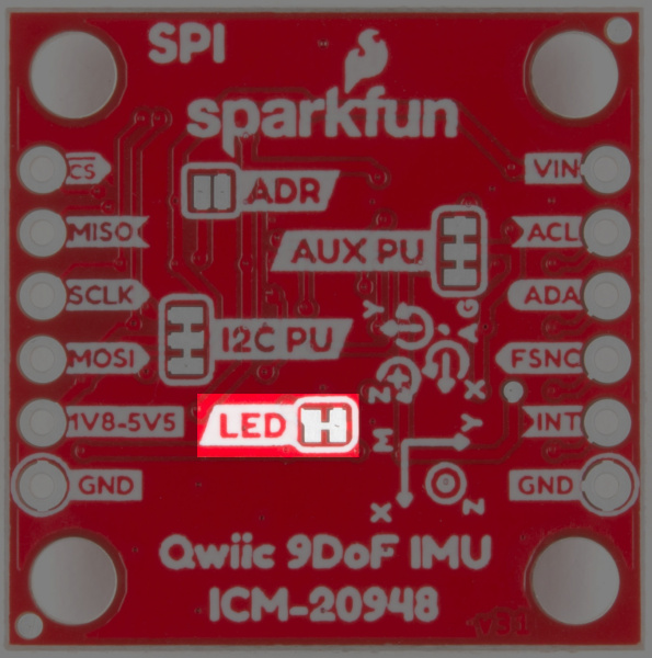
Input power on this board should be between 1.8-5.5V. The ICM is riding the wave of 1.8V level devices so we've included a built-in regulator to make it easy to interface with 3.3V or 5V microcontrollers. There is an LED on the front of the board that will light up when the board is powered correctly. You can disable the LED functionality by cutting the LED jumper on the back of the board. This is described in the Jumpers section below.
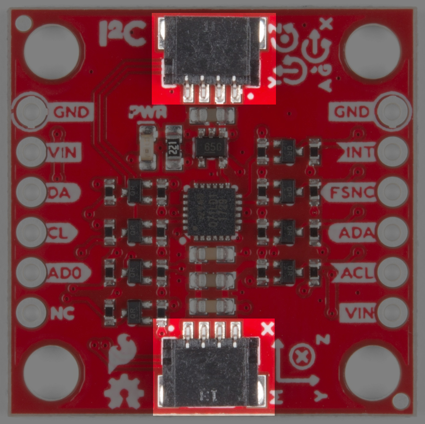
Qwiic Connectors
There are two Qwiic connectors on the board such that you can daisy-chain the boards should you choose to do so. If you're unfamiliar with our Qwiic system, head on over to our Qwiic page to see the advantages! Of course, if you don't want to use Qwiic we've still broken out every pin on 0.1" spaced plated through-hole headers. You can find more information about these connections in the Headers section.
GPIO
For flexibility, we've broken out functional pins for both I2C and SPI. There are no modifications required to switch between I2C mode and SPI out of the box, but if the 'ADR' jumper on the back is closed SPI will be unavailable.
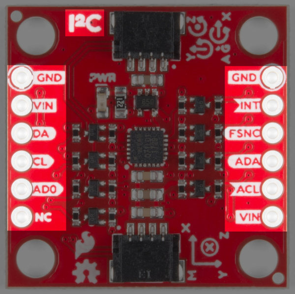 |
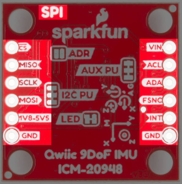 |
| I2C Pin Labels | SPI Pin Labels |
Jumpers
Look at all those jumpers on the back of the board! Here's what they do:
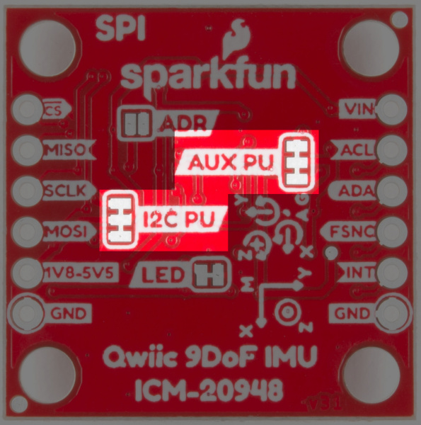
Pullup Jumpers
- I2C Pullup - Does nothing, the pullups are not populated on the board because the TXS0108 has them built-in
- Aux Pullup - Cut these jumpers to disconnect the pullup resistors from the auxiliary I2C bus
LED Jumper
- Cutting this jumper allows you to disable the LED functionality on the front of the board.
Address Jumper
- When open (default) the address of the ICM is 0x69 and it is possible to use SPI communication. When soldered closed the address changes to 0x68. Closing the jumper prevents you from using SPI.
 |
 |
 |
| Pullup Jumpers | LED Jumper | I2C Address Jumper |