SparkFun 9DoF IMU (ICM-20948) Breakout Hookup Guide
Introduction
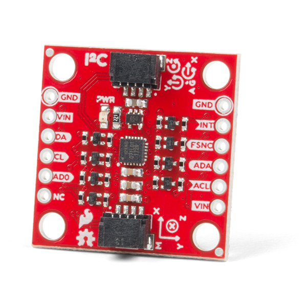
The SparkFun 9DoF IMU Breakout incorporates all the amazing features of Invensense's ICM-20948 into a Qwiic-enabled breakout board replete with logic shifting and broken out GPIO pins for all your motion sensing needs. The ICM-20948 itself is an extremely low powered, I2C and SPI enabled 9-axis motion tracking device that is ideally suited for smartphones, tablets, wearable sensors, and IoT applications. Featuring a 3-Axis Gyroscope with four selectable ranges, a 3-Axis Accelerometer, again with four selectable ranges, a 3-axis compass with a wide range to ±4900 µT, and an on-board Digital Motion Processor, this little breakout can even detect the motion of invisibility cloaks. Not really. Just checking to see if you were still with me. But it is pretty amazing. Check it out:
In this hookup guide, we'll connect our sensor up to our Esp32 Thing Plus microcontroller and run a of quick (Qwiic) example to get you up and running with this fantastic board!
Required Materials
To follow along with this tutorial, you will need the following materials. You may not need everything though depending on what you have. Add it to your cart, read through the guide, and adjust the cart as necessary.
Tools
If you choose to utilize the broken out GPIO, you will need a soldering iron, solder, and general soldering accessories.
Suggested Reading
If you aren't familiar with the Qwiic system, we recommend reading here for an overview.
| Qwiic Connect System |
We would also recommend taking a look at the following tutorials if you aren't familiar with them.
How to Solder: Through-Hole Soldering
Accelerometer Basics
I2C
Serial Terminal Basics
Hardware Overview
We've put a lot of effort into making this the most useful and versatile breakout for the ICM 20948. Let's take a closer look at all the special parts.
Sensor
At the heart of the board (metaphorically and geometrically) is the ICM 20948 from Invensense. This puppy packs the ability to measure up to 10 unique values (3 axes of acceleration, rotational rate, and magnetic strength data as well as an on-board temperature sensor). The sensor is placed dead-center between the four 4-40 stand-off mounting holes to drastically simplify computation in dynamics.
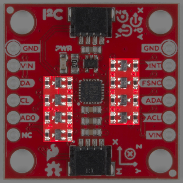
Level Shifters
The ICM is a fickle fellow - optionally allowing a 3.3V supply voltage but requiring I/O to work at 1.8V. This is just the price we pay for amazing technolojay (hey that rhymes). Since there aren't many popular development boards that run at the voltage of the future we've added high speed level shifting to each and every IO pin. These cool MOSFETS allow for bi-directional voltage translation up to the maximum SPI speed of the ICM - 7MHz - which will allow you to make inertial measurements with fantastic temporal resolution. Feel free to use the ICM IO anywhere from 1.8V to 5.5V!
Power
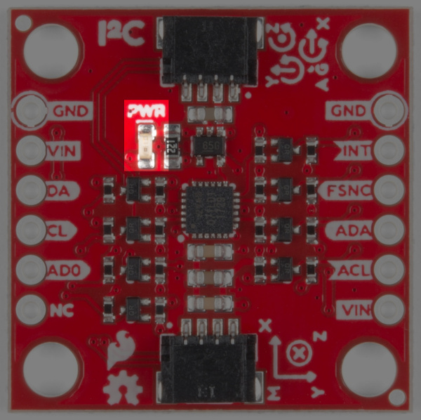
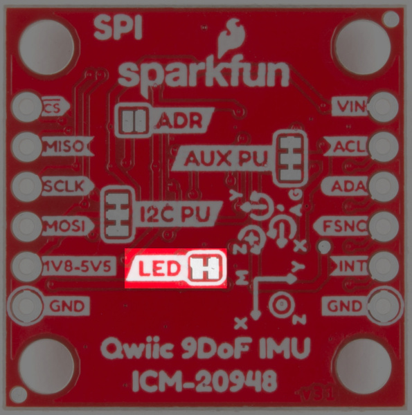
Input power on this board should be between 1.8-5.5V. The ICM is riding the wave of 1.8V level devices so we've included a built-in regulator to make it easy to interface with 3.3V or 5V microcontrollers. There is an LED on the front of the board that will light up when the board is powered correctly. You can disable the LED functionality by cutting the LED jumper on the back of the board. This is described in the Jumpers section below.
Qwiic Connectors
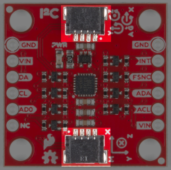
There are two Qwiic connectors on the board such that you can daisy-chain the boards should you choose to do so. If you're unfamiliar with our Qwiic system, head on over to our Qwiic page to see the advantages! Of course, if you don't want to use Qwiic we've still broken out every pin on 0.1" spaced plated through-hole headers. You can find more information about these connections in the Headers section.
GPIO
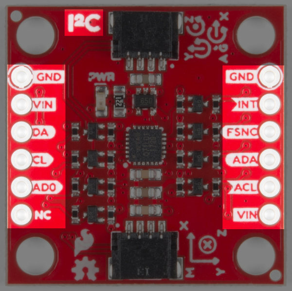
For flexibility, we've broken out functional pins for both I2C and SPI. There are no modifications required to switch between I2C mode and SPI out of the box, but if the 'ADR' jumper on the back is closed SPI will be unavailable.
 |
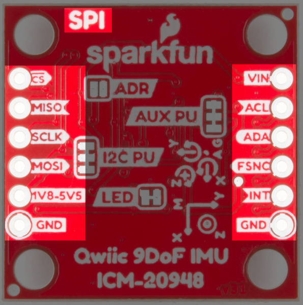 |
| I2C Pin Labels | SPI Pin Labels |
Jumpers
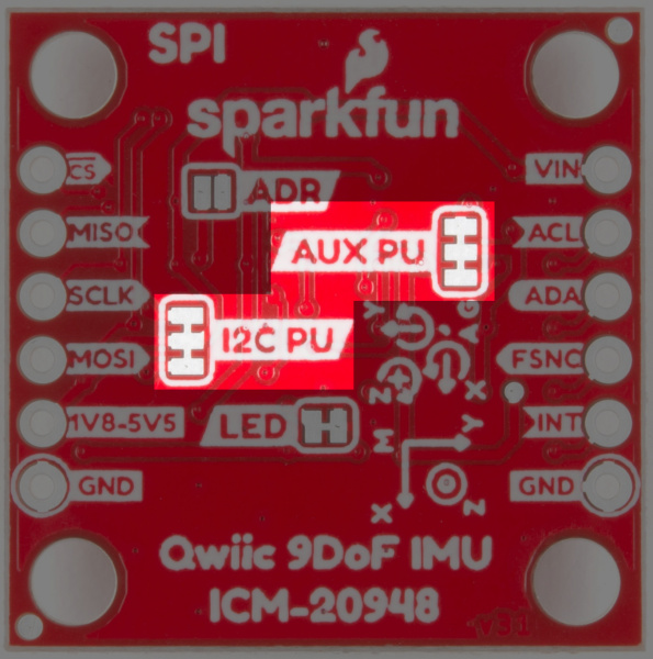
Look at all those jumpers on the back of the board! Here's what they do:
Pullup Jumpers
- I2C Pullup - Does nothing, the pullups are not populated on the board because the TXS0108 has them built-in
- Aux Pullup - Cut these jumpers to disconnect the pullup resistors from the auxiliary I2C bus
LED Jumper
- Cutting this jumper allows you to disable the LED functionality on the front of the board.
Address Jumper
- When open (default) the address of the ICM is 0x69 and it is possible to use SPI communication. When soldered closed the address changes to 0x68. Closing the jumper prevents you from using SPI.
 |
 |
 |
| Pullup Jumpers | LED Jumper | I2C Address Jumper |
Hardware Hookup
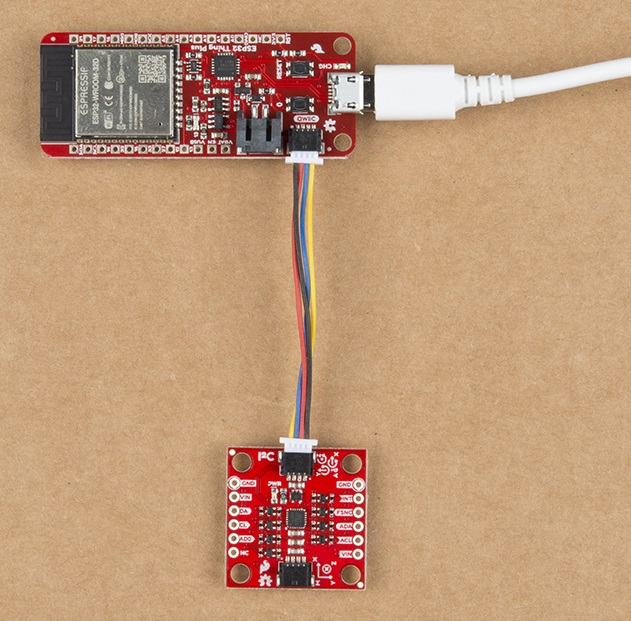
One of the many advantages of the Qwiic system is that hooking up your hardware is extremely simple. Simply grab a Qwiic cable and plug your 9DoF in!
If you are using the ESP32 Thing Plus, make sure your power supply is 5V, NOT 5.1V. We have noticed a power spike in our 5.1V power supplies, that can damage the IC on the ESP32 Thing Plus. Long cables can also generate a large enough voltage spike to damage the IC. We recommend keeping power supply cables shorter than 6 feet to minimize potential damage.
If you'd like to use the broken out GPIO pins, things get a bit more complicated. That said, to make life a little easier we've organized them by function, and provided lots of labels. You'll first notice that one side has the text 'I2C' and the other side says 'SPI.' The labels on either side are those that apply to that kind of communication.
 |
 |
| I2C Pin Labels | SPI Pin Labels |
Next, you'll see that on the left side are the main connections to the host microcontroller. When connecting I2C you'll have a 'No Connect' pin that serves as the chip select when using SPI. As noted before, there are no modifications required to switch between I2C mode and SPI out of the box. However if the 'ADR' jumper is closed SPI will be unavailable.
On the right side are connections to external sensors that can be controlled by the ICM, as well as the 'INT' and 'FSYNC' interrupt pins. The auxiliary I2C bus pins are level shifted to/from the 'VIN' level that you supply.
| Breakout Board Pin Functions (SPI) | |||
|---|---|---|---|
| Breakout Pin | Arduino Uno | Esp32 Thing Plus | Microcontroller Pin Requirements |
| MOSI | 11 | 18 | Data output of chosen SPI port |
| SCLK | 13 | 5 | Clock output of chosen SPI port |
| MISO | 12 | 19 | Data input of chosen SPI port |
| CS | 2 | 2 | An output pin to select the ICM for SPI |
| Breakout Board Pin Functions (I2C) | |||
|---|---|---|---|
| Breakout Pin | Arduino Uno | Esp32 Thing Plus | Microcontroller Pin Requirements |
| DA | SDA | 23 | Data line of chosen I2C port |
| CL | SCL | 22 | Clock line of chosen I2C port |
| AD0 | - | - | Optional - use to control I2C address from software |
| Breakout Board Pin Functions (Auxiliary I2C and Interrupts) | |||
|---|---|---|---|
| Breakout Pin | Arduino Uno | Esp32 Thing Plus | Microcontroller Pin Requirements |
| ADA | - | - | Data line of auxiliary I2C bus |
| ACL | - | - | Clock line of auxiliary I2C bus |
| FSYNC | - | - | Optional - synchronize measurements with a signal out from the microcontroller |
| INT | - | - | Optional - respond to configurable interrupts in from the ICM |
Software Setup and Example Code
In this example, we are using the SparkFun Esp32 Thing WROOM Plus. If you have not used this board before, head on over to the ESP32 Thing Plus Hookup Guide for a general overview, as well as information on getting set up with board definitions.
ESP32 Thing Plus Hookup Guide
In order to use the ICM-20948 breakout, you'll need to install the SparkFun ICM-20948 Arduino Library. We recommend you install the library via the Arduino IDE by using the library manager and search for Sparkfun 9DoF IMU Breakout. Or you can download and manually install a zip of the library by clicking on the link below. For those who want to view the code, check out the GitHub repo.
Example 1
In this example, we've hookup up our ICM-20948 to an ESP32 Thing Plus using a short Qwiic cable.
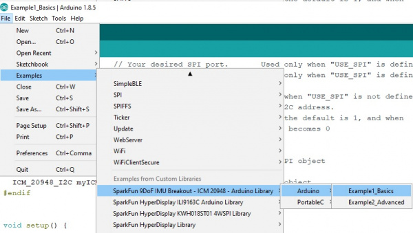
Once you've installed the ICM-20948 library, load the first example sketch from File->Examples->SparkFun 9DoF IMU Breakout - ICM 20948 - Arduino Library->Arduino->Example1_Basics.
The very first thing you'll see in the code is the #include statement for the library. Alongside that is a convenient link that will help you get the library through the Arduino library manager. Next is a commented out #define statement called 'USE_SPI'. If instead you have chosen to connect your ICM with the SPI pins all you need to do is uncomment that line.
language:c
#include "ICM_20948.h"  // Click here to get the library: http://librarymanager/All#SparkFun_ICM_20948_IMU

//#define USE_SPI       // Uncomment this to use SPI
Up next is a short section where you can configure your particular setup. First of all if you need to change your serial port, e.g. if you're using a SAMD21 board, you can change the 'SERIAL_PORT' define ('SerialUSB' for SAMD21). You can do the same to change your I2C port or SPI port, depending on which you're using. When using I2C you have the ability to change the I2C address of the sensor with the Address 0 bit. By default it is '1' but you could change it to 0 if you've closed the 'ADR' jumper. When using SPI you need to specify a chip select pin - in the example we default to pin 2.
language:c
#define SERIAL_PORT Serial

#define SPI_PORT SPI    // Your desired SPI port.       Used only when "USE_SPI" is defined
#define CS_PIN 2        // Which pin you connect CS to. Used only when "USE_SPI" is defined

#define WIRE_PORT Wire  // Your desired Wire port.      Used when "USE_SPI" is not defined
#define AD0_VAL   1     // The value of the last bit of the I2C address.
                        // On the SparkFun 9DoF IMU breakout the default is 1, and when
                        // the ADR jumper is closed the value becomes 0
That's it for stuff you (might) need to do to set up the example! Now we'll just all hop in the bus, take a tour, and I'll point out items on your right and left.
The next little block creates either a ICM_20948_I2C or ICM_20948_SPI object called 'myICM'. Since they have the same name, and they both inherit from the grandaddy ICM_20948 class, we'll be able to use them interchangeably later on in the example.
language:c
#ifdef USE_SPI
  ICM_20948_SPI myICM;  // If using SPI create an ICM_20948_SPI object
#else
  ICM_20948_I2C myICM;  // Otherwise create an ICM_20948_I2C object
#endif
In the setup() function we have your standard Arduino initialization of your serial port, and then we have the last interface-dependent section. There you'll see the 'myICM' object being started up with the appropriate arguments for the chosen interface. This example shows all arguments being explicitly stated, but it is also possible to call the .begin() function with default arguments. The initialization will repeat with a delay until the device is successfully found. If it is not connecting try checking your wiring.
language:c
#ifdef USE_SPI
    SPI_PORT.begin();
    myICM.begin( CS_PIN, SPI_PORT );
#else
    WIRE_PORT.begin();
    WIRE_PORT.setClock(400000);
    myICM.begin( WIRE_PORT, AD0_VAL );
#endif
Here's a little trick for debugging the ICM - nearly all operations will update the internal 'myICM.status' value. You can check it directly (0 means all good, anything else is an error) or you can use the statusString() method to get the latest status in human-readable form.
language:c
    SERIAL_PORT.print( F("Initialization of the sensor returned: ") );
    SERIAL_PORT.println( myICM.statusString() );
    if( myICM.status != ICM_20948_Stat_Ok ){
      SERIAL_PORT.println( "Trying again..." );
      delay(500);
    }else{
      initialized = true;
    }
The last part of the sketch is the loop() where the sensor gets polled for new data, and that data gets pushed over the serial port. All the data is contained in the 'AGMT' structure, which stands for Accelerometer, Gyroscope, Magnetometer, and Temperature sensors. For convenience this sketch also includes functions (that are not part of the library) to print the results in a pretty format.
language:c
void loop() {

  if( myICM.dataReady() ){
    myICM.getAGMT();                // The values are only updated when you call 'getAGMT'
//    printRawAGMT( myICM.agmt );     // Uncomment this to see the raw values, taken directly from the agmt structure
    printScaledAGMT( myICM.agmt);   // This function takes into account the sclae settings from when the measurement was made to calculate the values with units
    delay(30);
  }else{
    Serial.println("Waiting for data");
    delay(500);
  }

}
When you open up your Serial Monitor, you should see something like the following:
There ya have it! Now go ahead and hack it up.
Resources and Going Further
For more information on the ICM-20948, check out the links below:
- Schematic (PDF)
- Eagle Files(ZIP)
- ICM-20948 Datasheet
- ICM-20948 Arduino Library GitHub
- Qwiic_9DoF_IMU_ICM20948_Py Python Module
- 9DoF IMU GitHub
This tutorial focuses on using the 9DoF with Arduino. To use the ICM-20948 on a Raspberry Pi with Python, check out the Qwiic SHIM Kit Hookup Guide for Raspberry Pi for more information.
Qwiic SHIM Kit for Raspberry Pi Hookup Guide
Need more inspiration? Check out these related tutorials!
