Si4703 FM Radio Receiver Hookup Guide
Introduction
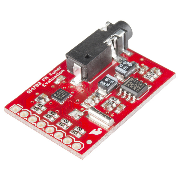
The Si4703 FM tuner evaluation breakout board enables you to tune in to FM radio stations, using the Si4703 FM tuner chip from Silicon Laboratories. This IC also works well for filter and carrier detection, and enables data such as the station ID and song name to be displayed to the user.
Required Materials
You will need the following materials to work on this project.
Keep in mind you will also need standard soldering materials to complete this tutorial, as well as either a set of speakers or headphones with a 3.5mm jack to plug into the Si4703 board.
Suggested Reading
If you aren't familiar with any of the concepts below, check out these links and get caught up before moving ahead with the Si4703.
Serial Communication
Installing an Arduino Library
How to Power a Project
Working with Wire
Using GitHub to Share with SparkFun
Using the Arduino Pro Mini 3.3V
Serial Terminal Basics
Hardware Overview
 |
 |
| V13 | V11 (Retired) |
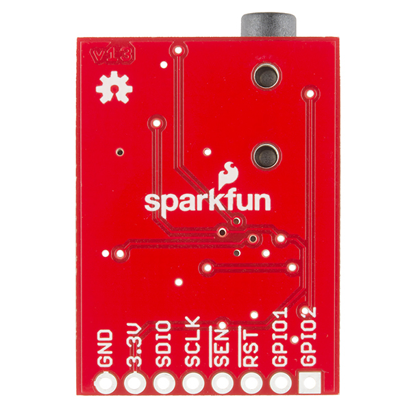
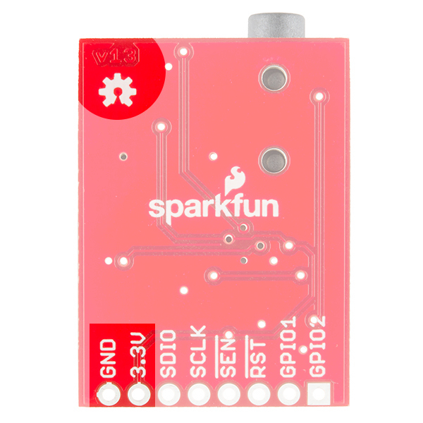
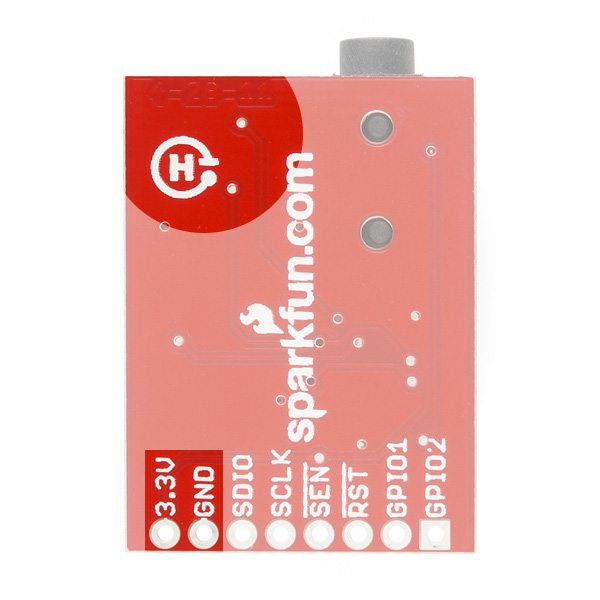
The Si4703 Breakout Board breaks out multiple pins from the IC. For the power bus, the 3.3V and GND pins are broken out. Keep in mind that while the IC is tolerant up to 5V, the communication pins are only 3.3V tolerant, and therefore should only be used in 3.3V systems. If you need to use this in a 5V system, check out our tutorial on using logic level converters.
For communication, the breakout board provides access to SDIO and SCLK for I2C communication. The RST pin is also broken out for ease of resetting the module.
SEN is also broken out, and enables the user to change the mode of functionality of the IC. SEN is pulled high on the breakout board to enable I2C communication as mentioned previously. However, by changing the state of SEN along with SDIO, you can change the mode of functionality between a 3-wire interface and 2-wire interface.
Finally, the last two pins broken out are the GPIO1 and GPIO2 pins. These can be used as general input/output pins, but also can be used for things like the RDS ready, seeking or tuning functions.
The board does not have a built-in antenna on it. However, by using headphones or a 3 foot-long 3.5mm audio cable, the wires will function as an antenna and will therefore negate the need for an external antenna on the board. If you are not planning on using either of these, you will need to modify the board to add in an antenna.
Hooking Up to an Arduino
First, you will need to prepare both the Si4703 board and the Arduino Pro Mini. Solder on the male headers to both boards. You will need headers on both the FTDI header, as well as the pins that you will be connecting to the Si4703.
Pin Connections
Once you have headers soldered, you will need to use the jumper wires to connect between the Si4703 and the Pro Mini. Remember, we are using a 3.3V Pro Mini to prevent damage to the logic on the Si4703.
Si4703 → 3.3V Pro Mini
- GND → GND
- 3.3V → VCC
- SDIO → A4
- SCLK → A5
- RST → D2
- GPIO2 → D3
You will then also need to hook up the Pro Mini to the FTDI board, and connect to your computer over USB.
Installing the Library
Now that the hardware is hooked up and connected, it's time to prepare to upload code. First you need to install the Arduino library into the IDE. If you are unaware how to do this, please check out our tutorial here. You can download the code here.
Once the library is properly installed, please open up the example sketch labeled "Si4703_Radio_Test". Make sure you select the "Arduino Pro or Pro Mini (3.3V, 8MHz) w/ ATMega328" under the "Tools -> Boards" heading. Select the proper COM port for your FTDI device under "Tools -> Serial Port". Upload the sketch to the board.
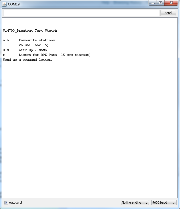
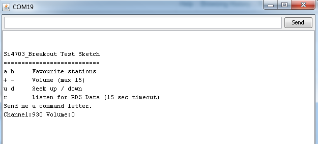
Once you have it uploaded, open up your Serial terminal (either through the Arduino IDE or your favorite terminal program). Open the connection with the settings 9600bps, 8, N, 1, and you should see the following displayed on the terminal.
You can then choose from any of the options listed. If you initially send the board option "a", you should see the following displayed back.
These favorite stations are pre-determined in the sketch, so feel free to change those to your own favorite stations if you would like.
else if (ch == 'a')
{
  channel = 930; // Rock FM
  radio.setChannel(channel);
  displayInfo();
}
else if (ch == 'b')
{
  channel = 974; // BBC R4
  radio.setChannel(channel);
  displayInfo();
}
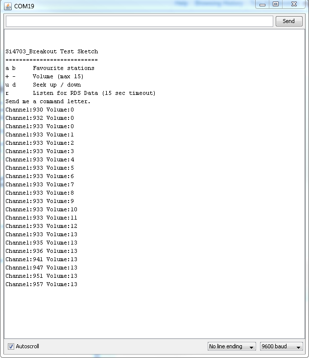
Keep in mind you will need to upload the code to the board again to update to the new stations. You can then direct the tuning either up or down, and control the volume of the board. For example, to tune to station 95.7 FM here in Boulder, I sent the commands: u, u, +, +, +, +, +, +, +, +, +, +, +, +, +, u, u, u, u, u, u. This results in the following in the serial terminal.
For this example, I am using my headphone wire as the anntena. Because of this, I was not necessarily able to receive stations that I often can when I'm not using a headphone wire as an antenna while connected to my computer (EMI is so much fun!). Play around with moving around or using different headphone wires and see how radio reception can change.
Resources and Going Further
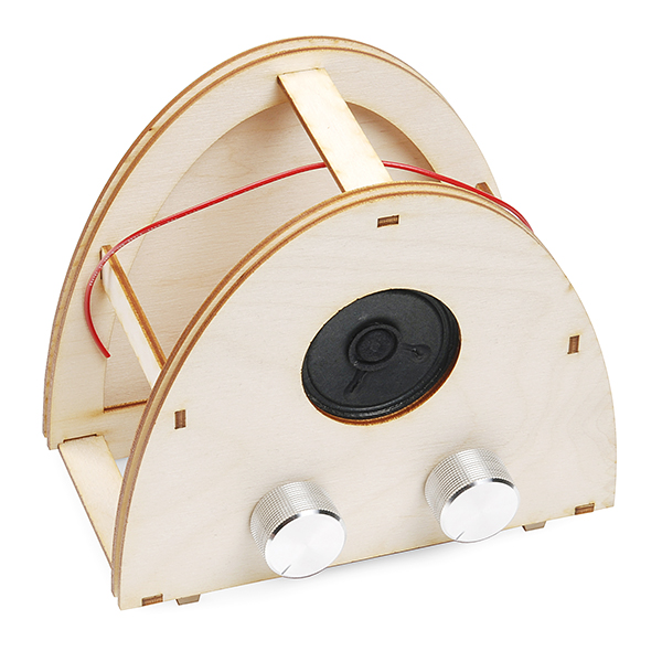
Now that you have your FM Tuner up and tuned to your favorite stations, you can start tweaking your circuit. You could add in a sensor to tune your board for you, have it set up on a timer with a clock, or place it in an enclosure like the FabFM Radio Kit. If you come up with a really cool project or mod, let us know! We'd love to hear about it.
FabFM Radio Kit
KIT-11043For more information about the Si4703 FM tuner evaluation board, check out the resources below:
- Schematic (PDF)
- Eagle Files (ZIP)
- Si4703 Datasheet (PDF)
- TPA6111A2 Datasheet (PDF)
- AN230 Programming Guide (PDF)
- AN243 Programming Guide (PDF)
- GitHub Repository
- SFE Product Showcase
Check out these additional resources for more information and other project ideas.
Rotary Switch Potentiometer Hookup Guide
Hackers in Residence: The Sound Visualizer Pt. 2
Hazardous Gas Monitor
SparkFun Inventor's Kit Experiment Guide - v4.1
If you have any feedback, please visit the comments or contact our technical support team at TechSupport@sparkfun.com.
