Sound Location with the Qwiic Sound Trigger and the u-blox ZED-F9x
 PaulZC
 Introduction
In this tutorial, we show you how to calculate the location of a sound using the SparkX Qwiic Sound Trigger and the u-blox ZED-F9P GNSS receiver.
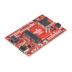
Qwiic Sound Trigger
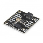
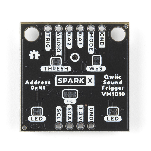
SPX-17979The Qwiic Sound Trigger can be used on its own, or as part of your Qwiic system. It is based on the VM1010 from Vesper Technologies and the TI PCA9536 GPIO expander. The VM1010 is a clever little device which can be placed into a very low power "Wake On Sound" mode. When it detects a sound, it wakes up and pulls its TRIG (DOUT) pin high. The VM1010 can then be placed into "Normal" mode by pulling the MODE pin low; it then functions as a regular microphone. The analog microphone signal is available on the AUDIO (VOUT) pin. All of this happens really quickly, within 50 microseconds (much faster than a capacitive MEMS microphone), so you don't miss the start of the audio signal. This makes it ideal for use as a sound trigger! If you turn the Qwiic Sound Trigger over, you will see a small hole ringed in white. That’s the opening for the microphone. You need to have the rear of the board pointing towards your sound source, not the front.
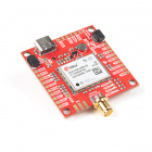
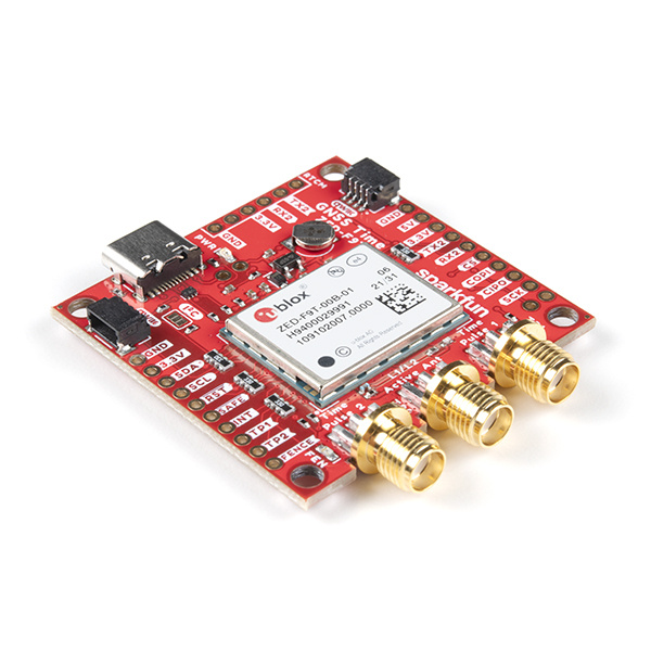
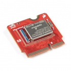
The u-blox ZED-F9P GNSS receiver is an old friend. It is a top-of-the-line module for high accuracy GNSS location solutions including RTK that is capable of 10mm, three-dimensional accuracy. With this board, you will be able to know where your (or any object's) X, Y, and Z location is within roughly the width of your fingernail! Something that doesn’t get discussed as much as it should is that the ZED-F9P can also capture the timing of a signal on its INT pin with nanosecond resolution! It does that through a UBX message called TIM_TM2.
Together, these two boards form the heart of our noise source location system. Want to figure out where a sound came from? These boards let you do that!
We are also going to show you how to log the TIM_TM2 data from the ZED-F9P to SD card using the MicroMod Data Logging Carrier Board and Artemis Processor Board. But our example code can be adapted to any board if required. Then we’ll go on to show how you can use our example Python code to process the data and calculate the location of the sound!
But first, let's talk about sound itself….
The Speed Of Sound
We all know that sound travels slower than light. If you see a flash of lightning, it can be several seconds before you hear the clap of thunder. It’s roughly 5 seconds for every mile. Count 15 seconds and the storm is 3 miles away from you. But let’s go metric.
The speed of sound is about 343.42 metres per second (767 mph). But it changes with both temperature and humidity. It is 343.42 m/s at 20 °C (68 °F) at 0% humidity. On a hot, cold or wet day, it changes. It changes with pressure / altitude too because the temperature of air is linked to its pressure through the Ideal Gas Law. You might remember that from your chemistry lessons at school.
The equation we are going to use for the speed of sound is:
| Speed of Sound (m/s) = 331.3 + 0.606T |
|---|
where T is the temperature in Celcius (Centigrade), not Kelvin.
So, the speed changes by approx. 0.6 metres per second or 0.2% for every degree change in temperature. We’ll include that in our calculations.
Calculating the Location of a Sound
Now that we know how fast sound travels, we can talk about how we go about calculating the location of the sound.
Let’s say that we have two sound triggers, one at each end of a corridor, and we want to calculate where the sound of footsteps came from. If the sound triggers are 10 metres (10m) apart and the footstep came from 3m away from one, 7m away from the other, then:
- It takes 3 / 343.42 = 8.74x10⁻³ seconds (8.74 milliseconds) for the sound to reach the first sound trigger
- It takes 7 / 343.42 = 20.38x10⁻³ seconds (20.38 milliseconds) for the sound to reach the second sound trigger
But how do we calculate the location if all we have is the time each sound trigger hears the footstep? Like this:
- We have a ZED-F9P at each end and timestamp each trigger event very accurately
- The difference between the two timestamps will be 11.65ms (20.38ms - 8.74ms)
- We can use the time difference to calculate the location, because we know how far apart the sound triggers are
- In 11.65ms sound travels 343.42 * 0.01165 = 4.0m
- We can calculate the distance from the first sound trigger by subtracting 4.0m from 10.0m and then dividing by 2
- Our sound came from 3.0m away from the first sound trigger
If we want to calculate the location of a sound in two dimensions, X and Y, or East and North, then we need three sound triggers so we can triangulate the location. We will show you how to do that in the next tutorial!
Accuracy and Sources of Error
Looking at the datasheet for the ZED-F9P high precision GNSS module, we see that it quotes a 99% accuracy for its time pulse signal of 60 nanoseconds. If we look at the datasheet for the ZED-F9T high accuracy timing module, we see that it offers a big improvement: 5 nanosecond accuracy for the time pulse in absolute timing mode; and 8 nanosecond time-mark resolution. So, really, if we want the highest accuracy, we should be using the ZED-F9T.
Now 60ns is really not very long. It is 0.00000006 of a second. But how far does sound travel in 60ns? If we multiply 343.42 by 0.00000006, we get 20.6 x 10⁻⁶ metres. Or 0.02 mm. OK. That’s pretty good! So we don’t need to worry too much about the timing accuracy of the ZED-F9P. And don’t forget that the TIM_TM2 message, which captures our time-mark or interrupt, has nanosecond resolution.
But what about our VM1010 sound trigger? Well, the datasheet doesn’t contain the numbers we really need, which is the minimum and maximum delay from the sound crossing the detection threshold to the TRIG (DOUT) signal going high. But, so long as there is not a big difference from chip to chip, the delay doesn’t really matter. If the time delay is fixed, it will cancel out in our calculations. But if one chip has a different delay to another, that will affect the accuracy. So let’s measure it!
Here is an oscilloscope trace of 100 sound events detected on two VM1010’s. The oscilloscope is being triggered by one VM1010 on the yellow trace. The purple trace is the TRIG (DOUT) signal from the second VM1010. They were being triggered by a short ‘click’ sound from a dog training aid. And, yes, we were careful to make sure they were both the same distance from the click!
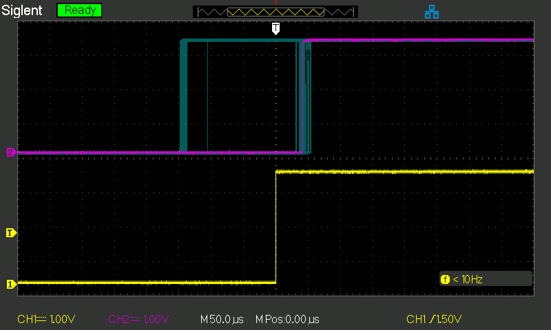
One of the interesting things I noticed is that when I press the button on the dog training aid, to produce the first of a pair of clicks, the output signal from the second VM1010 follows the rising edge group at ~140 microseconds before the first. When I release the button on the training aid, to make a second click, the output from the second VM1010 follows the group ~50 microseconds after the first. I don’t yet have a theory about why it does that… But it must have something to do with slight differences in the intensity or frequency spectrum of each click.
Anyway, if we take 140 microseconds to be the worst case error between these two VM1010’s, that corresponds to a distance of 343.42 * 0.00014 = 0.048m or 4.8cm. That’s still pretty respectable and not too far away from the accuracy we could expect if we were to survey-in the position of each sensing point.
In summary, we can make a hand-waving argument that we can expect the accuracy of our sound location system to be better than 10cm. Happy days!
Example Code
The GitHub Hardware Repo contains two examples for the Sound Trigger. You can run these in the Arduino IDE.
The first example, as the name suggests, is very simple. It uses the Qwiic (I2C / Wire) bus to communicate with the PCA9536 on the Sound Trigger. If a sound event is detected, you see a serial message showing how long it was since the last sound event. Then the event is cleared (reset) ready for the next one. The red LED on the sound trigger will light up briefly on each event. The LED on your board (LED_BUILTIN) will flash for a full second on each event.
The second example is the crowd pleaser! It runs on the MicroMod Data Logging Carrier Board together with the Artemis Processor Board but it should work just fine with any of our processor boards. It communicates with our ZED-F9P Breakout and the Qwiic Sound Trigger to capture sound events and log them to SD card as u-blox UBX TIM_TM2 messages.
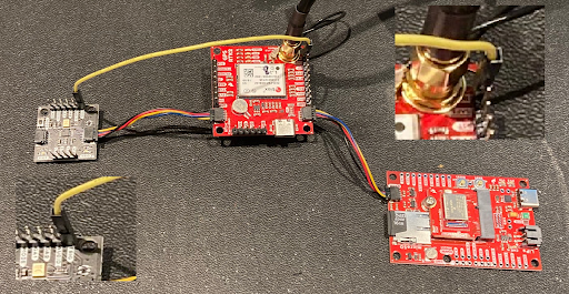
Hardware Connections
- Solder a 6-way row of header pins to the Qwiic Sound Trigger so you can access the TRIG pin.
- Please see the Data Logging Hookup Guide
- Insert the Artemis Processor into the MicroMod Data Logging Carrier Board and secure with the screw.
- Connect your ZED-F9P GNSS breakout to the Carrier Board using a Qwiic cable.
- Connect an antenna to your GNSS board. The antenna must have a clear view of the sky. Extend and feed the cable through a window if you need to.
- Insert a formatted micro-SD card into the socket on the Carrier Board.
- Connect the Qwiic Sound Trigger to the ZED-F9P using a second Qwiic cable.
- Use a jumper cable to connect the TRIG pin on the Qwiic Sound Trigger to the INT pin on the ZED-F9P breakout.
- Connect the Carrier Board to your computer using a USB-C cable.
To minimise I2C bus errors, it is a good idea to open the I2C pull-up split pad links on the MicroMod Data Logging Carrier Board and the u-blox module breakout and the Qwiic Sound Trigger.
Software Setup
- Ensure you have the SparkFun Apollo3 boards installed
- This code has been tested using version 1.2.1 of the Apollo3 boards on Arduino IDE 1.8.13.
- Select "SparkFun Artemis MicroMod" as the board type.
- Press upload to upload the code onto the Artemis.
- Open the Serial Monitor at 115200 baud to see the output.
Each time the Qwiic Sound Trigger detects a sound, it pulls its TRIG pin high. The ZED-F9P will detect this on its INT pin and generate a TIM_TM2 message. The Artemis will log the TIM_TM2 messages to SD card. You can then study the timing of the sound pulse with nanosecond resolution and calculate the location of the sound!
The code will "debounce" the sound event and reset the VM1010 for the next event after 250ms.
Note: TIM_TM2 can only capture the timing of one rising edge and one falling edge per navigation solution. So with setNavigationFrequency set to 4Hz, we can only see the timing of one rising edge every 250ms. The code "debounces" each sound event to make sure there will only be one rising edge event per navigation solution.
TIM_TM2 messages are only produced when a rising or falling edge is detected on the ZED-F9P’s INT pin. If you disconnect your TRIG to INT jumper wire, the messages will stop.
Data is logged in u-blox UBX format. Please see the u-blox protocol specification for more details. You can replay and analyze the data using u-center should you want to.
Analyzing the TIM_TM2 Data
Our Python Examples will process the UBX files for you to calculate the location of the sound events!
For the simplest two-sound-trigger set-up:
- Copy the TIM_TM2.ubx file from the SD card from the first system. Rename the file so you know which system it came from. You might want to call it TIM_TM2_1.ubx.
- Do the same for the TIM_TM2.ubx file from the second system. Again, rename it so you know which system it came from.
- Place both files in the same folder / directory as the Sound_Trigger_Analyzer_1D.py Python file
Run the Python code by calling:
language:python
python Sound_Trigger_Analyzer_1D.py TIM_TM2_1.ubx TIM_TM2_2.ubx 10.0 20.0
- Replace TIM_TM2_1.ubx with the name of the file from the first system as necessary
- Replace TIM_TM2_2.ubx with the name of the file from the second system as necessary
- Replace the 10.0 with the distance between your two sound triggers in metres
- The 20.0 is optional. It is the temperature in Celcius (Centigrade). Change this to your actual temperature for added accuracy
The Python code will open and analyze the two UBX files and extract the times of the sound events from the TIM_TM2 data. It will then look for pairs of events which are close enough together in time. For each pair it finds, it will calculate the distance of the sound from sensor 1. If you are testing this in a corridor, walking away from sensor 1 towards sensor 2, you will see the distance gradually increase with each footstep.
Next time, we take this to the next level with three systems doing 2D sound location! Stay tuned…