Setting up a Rover Base RTK System
 Nate
Nate Setting Up a Temporary Base
The first step in a base/rover setup is setting up a base station. There are a few ways to set up a base station: a temporary base station is faster but less precise. A static base station takes more time to set up and configure but provides the greatest precision. There is a third option and that is getting your correction data from a public feed. That option is covered in this tutorial and so we will not cover public correction data in this tutorial.
We’ve covered setting up a temporary base station in a previous tutorial but we will go a bit more in depth here. Additionally, this tutorial will cover the settings required for the ZED-F9P (rather than the previous generation NEO-M8P).
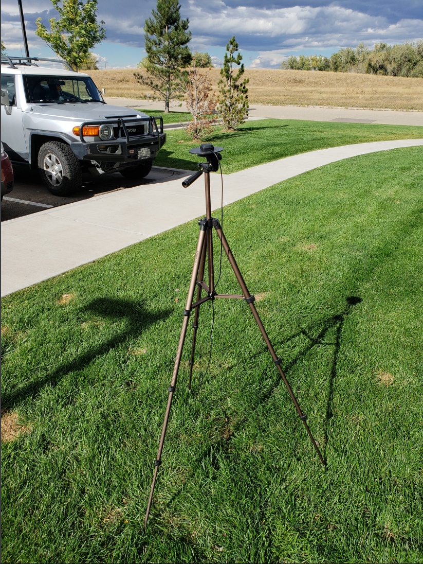
Above is the u-blox antenna attached to the ground plate, on top of a tripod, with SMA cable running indoors to the receiver. This is a great setup for experimenting and for short trips to the field. The purpose of a GNSS RTK base is to not move. Once you tell a receiver that it is a base station (ie, not moving) it will begin to look at the satellites zooming overhead and calculate its position. As the environment changes the signals from the GNSS (Global Navigation Satellite System - the collective term for GPS, GLONASS, Beidou, Galileo satellites) network change and morph. Because the base knows it is motionless, it can determine the disturbances in the ionosphere and troposphere (as well as other error sources) and begin to calculate the values needed to correct the location that the satellites are reporting to the actual location of the base station. These values are unsurprisingly called ‘correction values’ and are encoded into a format called RTCM. (RTCM stands for Radio Technical Commission for Maritime but is just a name for a standard akin to “802.11”. Don’t worry about it.). You will often see the term RTCM3 being used; this is simply correction data being transmitted using version 3 of the RTCM format.
Ok, so how do we set up a base? You’ll need the following:
Things you will need:
- A ZED-F9P receiver with a USB cable connected to your computer.
- A clear view of the sky. Not indoors, not near a window, outside with nothing around. The accuracy of the entire system depends on the ability to see as many satellites as possible.
- An antenna. We enjoy and promote the use of low-cost antennas and gear. You can easily spend >$2,000 on a commercial grade GNSS antenna but we’ve had great success with the u-blox L1/L2 antenna. You must absolutely have an antenna that is L1/L2 compatible. A simple magnetic GPS antenna will receive L1 frequencies but RTK will be very inaccurate if it’s even possible.
- If your antenna does not have a built in ground plane (the u-blox antenna does not) you will need to add a metal ground plate. A car’s roof will act as a ground plate as well.
- A tripod or car roof to mount the antenna. We’ve found cheap camera tripods work fine. We designed the ground plates to have a compatible 1/4"-20 hole so they screw directly onto the tripod.
- A way to get the RTCM correction data to the rover: computer with internet connection, serial point to point radio, XBee modules, etc. We will be using the 915MHz Serial Telemetry Radio kit.
- An SMA extension cable (~10m or whatever you need to get from outside to your work computer).
Note: The accuracy of the base’s location will be reflected in the accuracy of the rover’s position. Said differently, if the base is incorrectly recorded 1m away from its actual location than all the rover readings will be exactly 1m wrong. It’s really important to locate the antenna with a clear view of the sky and to obtain an accurate base station location.
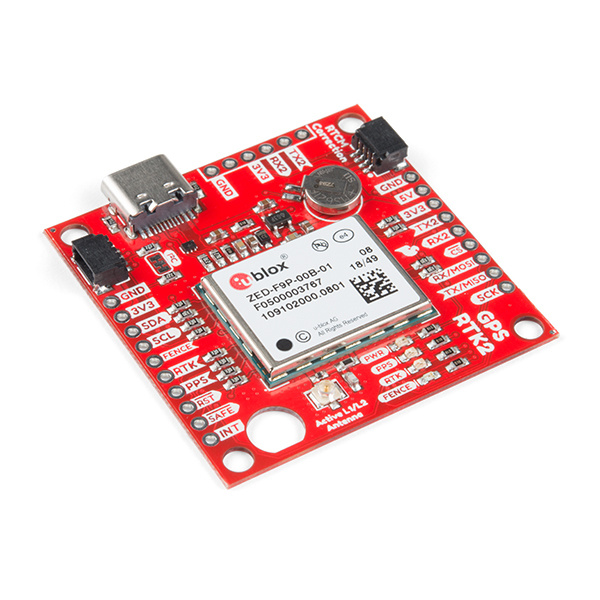
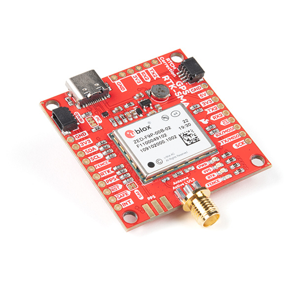
Once you’ve got the antenna in place, connect the ZED-F9P to USB and to the antenna. We offer two variants of the Qwiic RTK. If you’ve got the SparkFun GPS-RTK2 with U.FL antenna connection, you’ll need to connect the U.FL to SMA adapter. Here are some good pictures to show you how to correctly connect a U.FL cable. If you’ve got the SparkFun GPS-RTK-SMA simply screw the antenna onto the SMA connector.
Open u-center and connect to the corresponding COM port that Windows created when the board was connected.
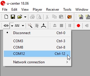
Having Problems With COM Ports? Please checkout our tutorial on u-center specifically. It will walk you through driver install and determining which COM port is the receiver.
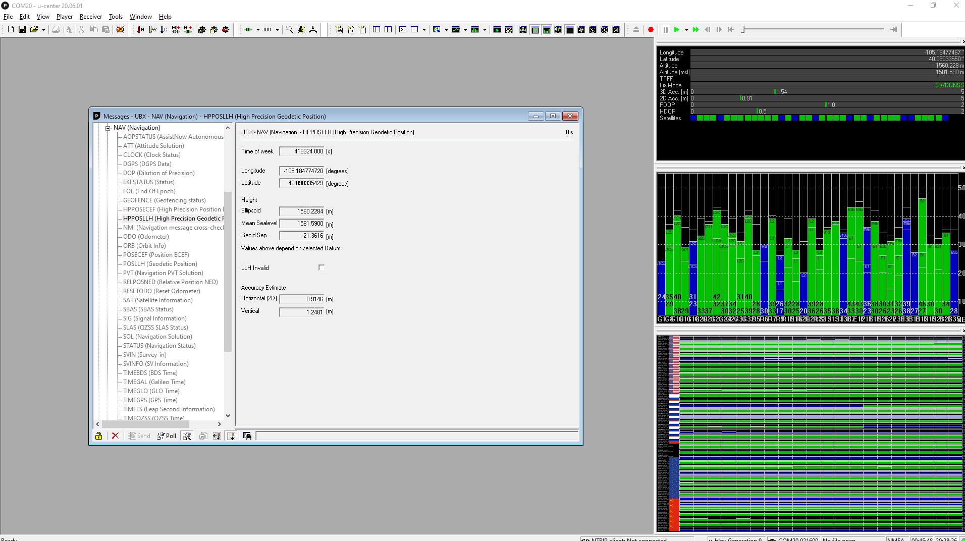
You should begin to see things change and data flowing through. Above shows the ZED-F9P running for a few minutes obtaining a heap of satellites and achieving 0.9m horizontal accuracy. Let’s open the Messages window and begin configuring the module.
First, close the NMEA branch to get it out of the way. Open the UBX branch and then the CFG configuration branch. The number of configuration options can be overwhelming at first but over time they can become quite helpful. We are looking for MSG.
Take this moment and ask yourself how you will be transmitting the correction data from the base to the rover. The correction data, or RTCM, varies in size but is approximately 1 to 2k bytes per second. Tiny compared to downloading a song or video, but just large enough that LoRa and smaller packet radios may not be able to handle it. We recommend using a Serial Telemetry Radio. Running at 915MHz, these radios can hit ~300m out of the box at 100mW with a 2km/500mW option available as well. The radios act as a transparent serial passthrough at 57600bps (out of the box). We’ve found them to be just about perfect for Base to Rover RTCM communication with the only limitation being distance. If you need miles of range, you will need to get your HAM radio license and crank the power. But if you’re just getting started with RTK, these radios are great!
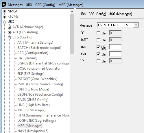
We are going to assume a telemetry radio will be attached to UART2 of the ZED-F9P. From u-center Messages window, enable the following messages for both UART2 and USB.
- RTCM3.3 1005
- RTCM3.3 1074
- RTCM3.3 1084
- RTCM3.3 1094
- RTCM3.3 1124
- RTCM3.3 1230 x 5 (Enable message every 5 seconds)
As you set each setting, you will need to press the ‘Send’ button. It doesn’t hurt to press the ‘Poll’ button to verify the setting has stuck.
We recommend enabling these messages for both USB and UART2 as shown in the photo. This will tell the module to begin transmitting just these RTCM sentences (message types) once the module has completed its survey. UART2 is best used for sending serial RTCM in/out. USB is enabled so that we will be able to see and verify that RTCM messages are actually being output by the module.
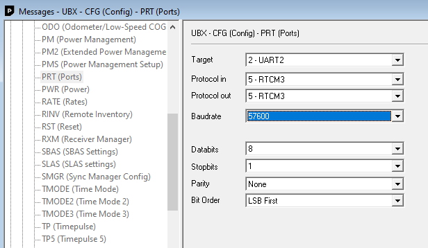
Next, set UART2 to the appropriate baud rate. Scroll down to the ‘PRT’ or port settings. Select UART2. By default it is 38400bps and the radios expect 57600bps. Increase the speed. Remember to press ‘Send’.
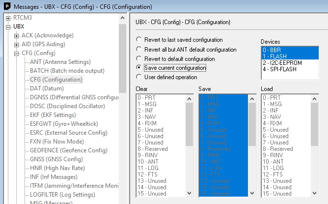
Now scroll up to the CFG or config option. This menu allows us to save the current settings. When you plug in your module again, you won’t have to re-do all these settings. BBR is battery backed RAM. There is a small battery on the SparkFun GPS-RTK boards that should maintain the settings for over a week. The Flash setting records the settings to flash memory as well so if the battery loses power, flash will maintain the settings (also called non-volatile memory or NVM).
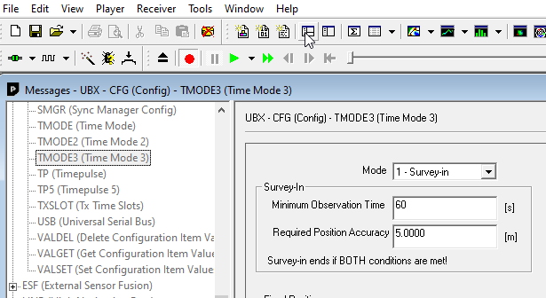
The last thing to do is to initiate a survey in. Navigate to the TMODE3 menu, set the mode to '1 - Survey-In', set the observation time to 60s, and required accuracy to 5m. These are the settings that u-blox recommends. Press ‘Send’ and sit back. It can take many minutes for the module to obtain enough fixes to have a standard deviation less than 5m.
Note: You can enter the observation time and required accuracy values then save the current settings to BBR/Flash. This will effectively tell your module to survey-in at every power-on. This can be handy in many field deployments where u-center is not available but use it with caution. I have been very confused a few times when my device stopped updating its position because I had left it in survey-in mode and didn’t realize it.
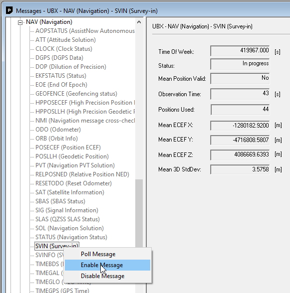
To monitor the status of the survey, scroll down, exiting the CFG section and enter the NAV section. Right click on ‘SVIN’ and click on Enable Message. This will tell the module to send the status of this register every second. Once the module has gotten 60s of data and the mean standard deviation is less than 5m then the survey will report ‘Complete!’. This module’s lat/long/height will no longer change because it has been fixed.
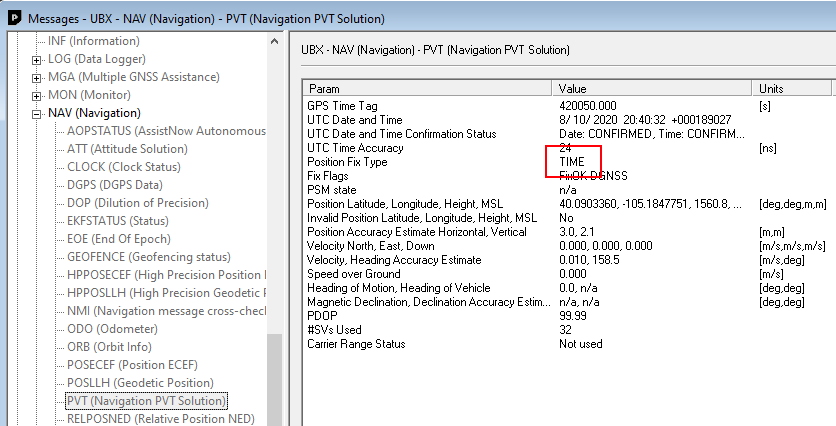
You can verify the survey in is complete by checking the PVT message. If the Fix Type is ‘TIME’ then you know you have successfully setup a base. Congrats!
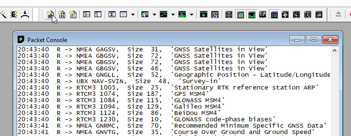
Furthermore, we can view the RTCM messages. Open the packet console. If the RTCM messages have been enabled and the survey-in is complete, we should see the RTCM messages scroll by. Note: The RTCM messages are not visible ASCII like NMEA sentences, they are encoded bytes of data. You can't 'see' them in the Text Console but they are shown in the Packet Console.
What about fast update rates? The ZED-F9P is capable of outputting up to 30Hz fix rates. This is an astounding amount of math. “Isn’t moar, better?”™ Not really for RTK. The base is transmitting correction values once per second. We could increase the output of the module to 4 or 10Hz, but because the conditions between you and the satellites are not changing that quickly, it really only bogs down your radio link.
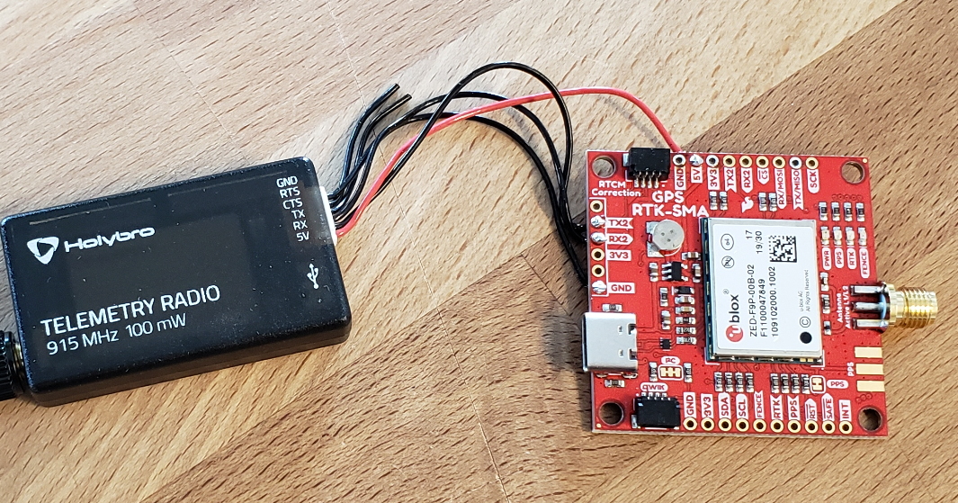
The last thing we need to do is attach our radio. Cut the 6 pin JST-GH cable that came with the Serial Radio Telemetry kit in half. Plug the cable into one radio and note where the TX, RX, 5V and GND pins fall. Go slow. I wired TX/RX backwards and caused myself an hour’s worth of grief. I recommend stripping one wire at a time as this makes it clear which wire I’m working on. Solder the wires as follows:
- Radio 5V - RTK 5V
- Radio TX - RTK RX2
- Radio RX - RTK TX2
- Radio GND - RTK GND
For the advanced readers of this tutorial, go ahead and wire solder the second radio cable to your rover module in exactly the same way.
Shown above, I wired the radio to the 6-pin UART2 header. This space is normally used for the 6-pin connection to a Bluetooth module so if you’d like to leave those pins open (for future potential Bluetooth) you can also solder the radio to the TX2/RX2 pins on the side of the GPS-RTK board. We wired the radio to 5V instead of 3.3V on the 6-pin header. We have seen the radios work at 3.3V but a high voltage should get you the maximum transmit distance.
Now is a good time to mark your module with a sharpie or a ‘BASE’ label so you know which module is which.
Advanced User Trick
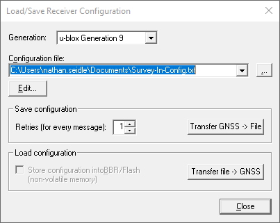
Rather than hunting and pecking each individual setting it can be handy to have various configuration files at the ready to configure a given module. Click on Tools->Receiver Configuration. This will allow you to save the current configuration to a file and load it onto a new unit. Here is the survey-in prep configuration that I use (RTCM messages enabled, UART2 set to 57600, no survey-in settings). Save the link as 'survey-in-config.txt' and load using u-center. Once you load the config be sure to record it to BBR/Flash.