Series and Parallel Circuits
Experiment Time - Part 3, Continued...
For the first part of this experiment, we’re going to use one 10K resistor and one 100µF (which equals 0.0001 farads). These two parts create a time constant of 1 second:
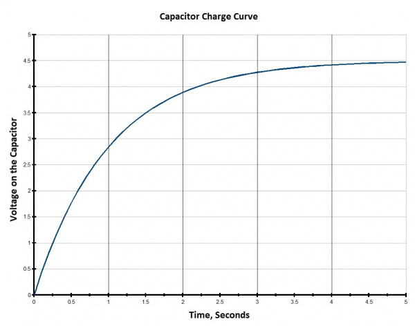
When charging our 100µF capacitor through a 10kΩ resistor, we can expect the voltage on the cap to rise to about 63% of the supply voltage in 1 time constant, which is 1 second. After 5 time constants (5 seconds in this case) the cap is about 99% charged up to the supply voltage, and it will follow a charge curve something like the plot below.
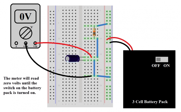
Now that we know that stuff, we’re going to connect the circuit in the diagram (make sure to get the polarity right on that capacitor!).
With our multimeter set to measure volts, check the output voltage of the pack with the switch turned on. That’s our supply voltage, and it should be something around 4.5V (it'll be a bit more if the batteries are new). Now connect the circuit, taking care that the switch on the battery pack is in the “OFF” position before plugging it into the breadboard. Also, take care that the red and black leads are going to the right places. If it’s more convenient, you can use alligator clips to attach the meter probes to the legs of the capacitor for measurement (you can also spread those legs out a bit to make it easier).
Once we’re satisfied that the circuit looks right and our meter’s on and set to read volts, flip the switch on the battery pack to “ON”. After about 5 seconds, the meter should read pretty close to the battery pack voltage, which demonstrates that the equation is right and we know what we’re doing. Now turn the switch off. It’s still holding that voltage pretty well, isn't it? That’s because there's no path for current to discharge the capacitor; we've got an open circuit. To discharge the cap, you can use another 10K resistor in parallel. After about 5 seconds, it will be back to pretty close to zero.


