If you're ready to step up your Arduino game from older 8-bit/16MHz microcontrollers, the ATSAMD21 is an awesome alternative. The ATSAMD21G18 is an ARM Cortex M0+, 32-bit microcontroller that can run at up to 48MHz, and it comes complete with 256KB of flash memory and 32KB of SRAM. Plus, best of all, it's fully supported in the Arduino IDE!
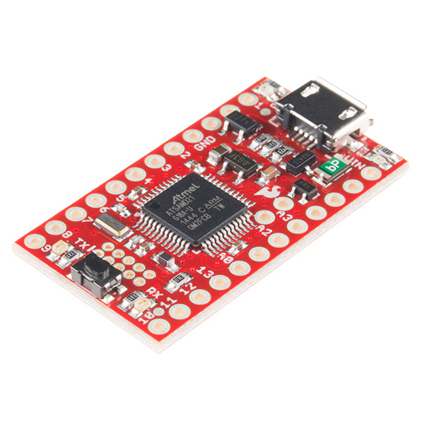
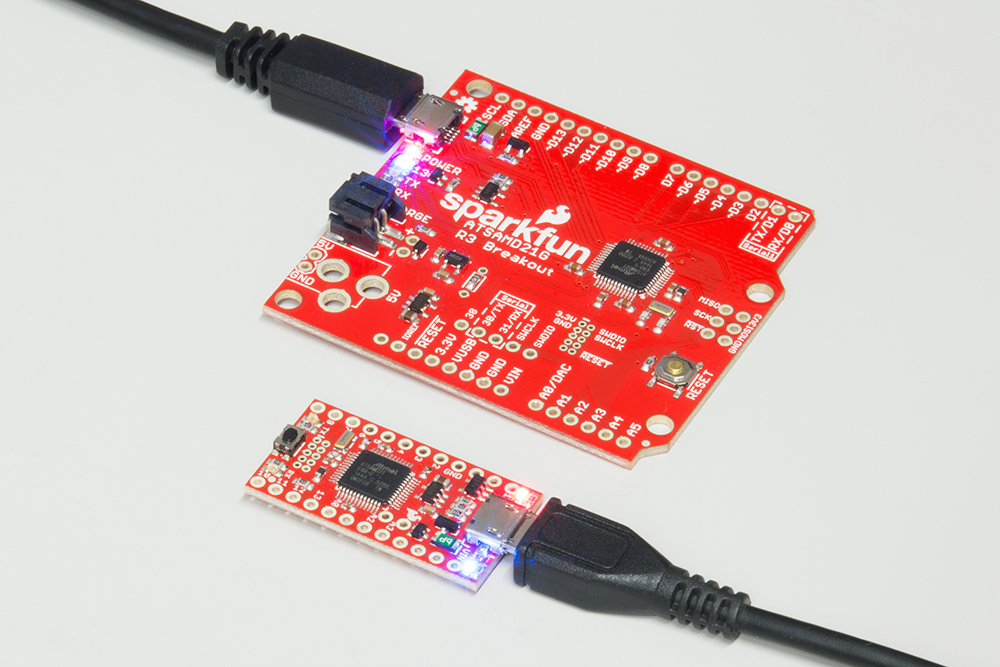
SparkFun has come up with two new breakout boards for the ATSAMD21G18, both coming in familiar shapes. There's the full-size, Arduino-shaped SAMD21 Dev Breakout. And the minuscule, Pro Mini-shaped SAMD21 Mini Breakout.
Both boards have similar feature sets -- they equip the ATSAMD21G18 with a USB interface for programming and power, then surround it with an RTC crystal, 600mA 3.3V regulator, and a variety of other components. The Dev Breakout's extra PCB real-estate leaves room for extra GPIO and an integrated LiPo charger.
This tutorial covers, from the ground up, all things ATSAMD21 and the SparkFun Mini and Dev Breakout boards. It's split into a number of pages, including:
Serial, Serial1, and SerialUSB.In addition to either of the SAMD21 Breakout Boards, you'll also need a Micro-B Cable (as if you don't already have dozens in your USB cable drawer!). That's all you'll need to get started. But...
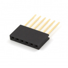
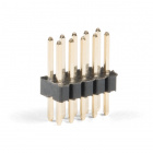
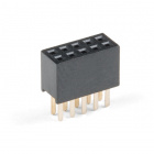
Eventually you'll want to solder something to the board. If you don't already have soldering tools, a soldering iron and some solder may also come in handy. You can choose your own adventure when it comes to soldering connectors into the boards. Any of these headers (or wire) may come in handy:
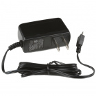
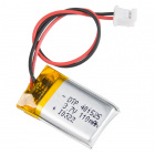
If you have a SAMD21 Dev Board, you can take advantage of its LiPo charger with a single-cell Lithium Polymer battery, and/or solder a PTH Barrel Jack in to power it with a 5V Wall Adapter.
Before continuing on with this tutorial, you may want to familiarize yourself with some of these topics if they’re unfamiliar to you:
Atmel's ATSAMD21 (the ATSAMD21G18A to be exact) is a 32-bit ARM Cortex-M0+ microcontroller, which means it's world's different from the 8-bit AVR's you may be familiar with. Comparing the SAMD21 against our old favorite -- the ATmega328P -- isn't very fair, but we're going to do it anyway.
| Feature | ATSAMD21G18A | ATmega328P |
|---|---|---|
| Architecture | ARM Cortex-M0+ | AVR |
| Bus Size | 32-bit | 8-bit |
| Max CPU Speed | 48MHz | 20MHz |
| Flash | 256KB | 32KB |
| SRAM | 32KB | 2KB |
| EEPROM | 32KB (emulated in Flash) | 1KB |
| Voltage Range | 1.62-3.63V | 1.8-5.5V |
| GPIO Count | 38 | 23 |
| ADC Channels | 14 | 8 |
| ADC Resolution | 12-bit | 10-bit |
| Digital-to-Analog Converter (DAC) | Yes | No |
| USB Controller | Yes | No |
| Direct Memory Access (DMA) | 12 Channels | No |
| Peripheral Touch Controller | Yes | No |
| Inter-IC Sound I2S | Yes | No |
Okay...mercy rule. This isn't to say there aren't benefits to the ATmega328's: they're well-documented, have huge support in the community, are simpler to wrap your head around, and can operate at 5V. There'll always be a place in the world for the ATmega328P, but -- especially as price point's get closer -- there are many good reasons to consider the SAMD21.
This page will discuss some of the features that make the SAMD21G18 a unique step above the ATmega328P.
If you've ever run into the program storage limits of an Arduino Uno, felt hampered by an Arduino Pro Mini's 8MHz operating speed, or had to troubleshoot those mysterious dynamic memory (SRAM) stack overflows, you may know why the SAMD21's larger memory-capacities are so exciting.
The SAMD21's 256KB of flash means you shouldn't ever have to worry about fitting your compiled sketch into a tight 32KB space. That extra flash can be used to store large, user-defined blocks of data as well, with libraries like FlashStorage.
The SAMD21 will process your instructions much faster too. Not only can it run at more than double the speed of an AVR, but it's also helped by the 32-bit architecture. While the AVR has to divide processing of large data types into 8-bit sections, the SAMD21 can process large blocks of data in single, fell swoops.
One of the most unique features of the SAMD21 is SERCOM -- a set of six configurable serial interfaces that can be turned into either a UART, I2C master, I2C slave, SPI master or SPI slave.
Each SERCOM provides for a lot of flexibility: the ports can be multiplexed, giving you a choice of which task each pin is assigned. Here's an overview of which pins can be configured to which SERCOM interface (the pins names have been Arduino-ified):
| SERCOM0 | SERCOM1 | SERCOM2 | SERCOM3 | SERCOM4 | SERCOM5 | |||||||
|---|---|---|---|---|---|---|---|---|---|---|---|---|
| PAD0 | A3 | D4 | RTC1 | D11 | D4 | MISO | D11 | SDA | MISO | A1 | SDA | A5 |
| PAD1 | A4 | D3 | RTC2 | D13 | D3 | D38 | D13 | SCL | D38 | A2 | SCL | RXLED |
| PAD2 | D8 | D1 | SWCLK | D10 | D1 | D2 | D10 | D6 | MOSI | D2 | D30 | D6 |
| PAD3 | D9 | D0 | SWDIO | D12 | D0 | D5 | D12 | D7 | SCLK | D5 | D31 | D7 |
| Arduino Default | Dev Board Only (Not broken out on Mini) | In-Use | ||||||||||
| ||||||||||||
In the Arduino IDE, SERCOM0 and SERCOM5 are assigned to UARTs (laying claim to pins 0, 1, 30, and 31 respectively), SPI defaults to SERCOM4 (pins MISO, MOSI, and SCLK), and I2C is SERCOM3 (SDA and SCL). That leaves SERCOM1 and SERCOM2 that you can bend to your will -- make pins 3 and 4 I2C, or turn pins 10-13 back into SPI (like the good, old days).
With the ability to create multiple UARTs or other serial interfaces, you may never have to bitbang SPI, or debug around SoftwareSerial again!
For more information about adding more SERCOM ports for your SAMD-based board, check out the tutorial below.
Like the ATmega32U4 on the Arduino Leonardo and SparkFun Pro Micro, the ATSAMD21 is equipped with an integrated USB controller. It can be used as either a USB device or host.
In device mode, the SAMD21 can emulate a keyboard, mouse, or joystick, work as a mass storage device, or communicate as if it were a serial port. Device mode is a critical part of the SAMD21's USB-programmability. It configures itself as a USB CDC (communication device class), so your computer can talk to it as if it were a serial port.
As a USB host, the SAMD21 can connect up to a keyboard or mouse, or even save data to a USB flash drive. It takes some extra power-supply-planning to get the SAMD21 to work as a USB host, but it can be a rewarding component of your project.
Almost every pin on the SAMD21 is tied to a timer-counter, which means you'll see a lot more PWM-capable I/O pins. In fact, all digital pins besides D2 and D7 can be used with the analogWrite function. You'll have plenty of options for dimming LEDs or controlling motor drivers.
Real time clocks (RTC) can be critical components in projects that need precise time-keeping -- whether it's for creating a digital clock or a controlled PID loop. While the ATmega328 does have an RTC, you'll need to sacrifice clock cycles for time-keeping, by swapping out the 16MHz crystal for one running at 32.768kHz. The SAMD21 has a separate real-time clock system, powered by an on-board 32.768kHz crystal, and it still clocks the processor at 48MHz.
The SAMD21G18 has 14 total ADC input pins, each with 12-bit resolution. That increased resolution means every bit between 0 and 4095, represents about 0.806mV (assuming the processor is powered at 3.3V), allowing for more sensitive voltage measurements. Analog reference pins are also available, if you need to further fine-tune the ADC system.
The SAMD21 also features a digital-to-analog converter (DAC) output, for creating truly analog signals. The DAC has up to 10-bit resolution, and can convert up to 350,000 samples per second (350ksps). The analog output pin is shared with the Arduino "A0" pin -- it's the only one you get, so use it wisely!
Before we get into programming the SAMD21, this page briefly covers some of the features built into the SAMD21 Dev Breakout. If you're reading this guide with a mind toward the Mini Breakout, consider skipping ahead to the Mini Breakout overview.
If you've used any Arduino before, this pinout shouldn't surprise you -- the layout meets the Arduino 1.0 footprint standard, including a separate SPI header and additional I2C header. For a quick reference, consult our graphical datasheet, which exhaustively shows the capability of each I/O pin and some of the other features on the board.
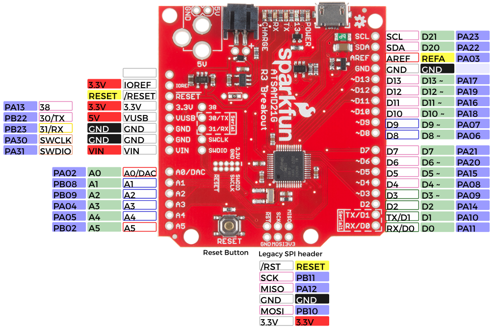
All PWM-capable pins are indicated with a tilde (~) adjacent to the pin-label. Speaking of "analog output", true analog output is available on the A0 pin -- indicated with a shared DAC label.
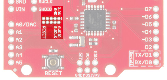
In addition to the standard I/O footprints, the board also breaks out a few additional pins towards the inside of the board. These pins can be referenced in Arduino by the adjacent silkscreen number (30, 31, and 38).
The Cortex Single-Wire Debugger (SWD) pins -- SWCLK and SWDIO -- don't have Arduino-style reference numbers, though they can be used as GPIO pins.
⚡ 3.3V Logic Levels! When you start interfacing the SAMD21's I/O pins with external sensors and other components, keep in mind that each I/O will produce, at most, 3.3V for a high-level output.
When configured as an input, the maximum input voltage for each I/O is 3.6V (VDD+0.3V). If you're interfacing the SAMD21 with 5V devices, you may need some level shifters in between.
Power can be supplied to the SAMD21 Breakout through either USB, a single-cell (3.7-4.2V) lithium-polymer battery, or an external 5V source. Each of the power supply inputs are available on the top edge of the board (the VIN pin on the power header can also be used).
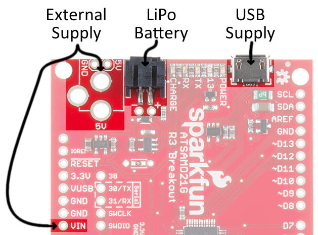
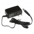
The USB jack is of the micro-B variety. It should work with one of the many USB phone-charging cables you have lying around, or one of our Micro-B cables. You can plug the other end into a computer USB port, or use a USB Wall Adapter. The USB supply input includes a 500mA PTC resettable fuse -- if something on or connected to the breakout fails, it should help protect your supply from damage.
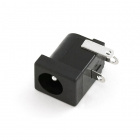
The unpopluated supply input fits our PTH Barrel Jack connector, which would go well with a 5V, Center-Positive Wall Adapter.
Find out more about powering the SAMD21 off a lithium-polymer battery -- and charging that battery -- in the LiPo charger section below.
The on-board AP2112K 3.3V regulator is low-noise, low-dropout, and can supply up to 600mA, but has a maximum input voltage of 6V. Try not to use any supply larger than 5V.
The SAMD21 touts many low-power features, so using it in battery-powered projects should be a common occurence. We've integrated our standard 2-pin JST connector, and a single-cell USB battery charger into the board. Any of our single-cell lithium polymer batteries can be used to power the board.

To charge the battery, simply connect USB or a 5V supply while the battery is also connected.
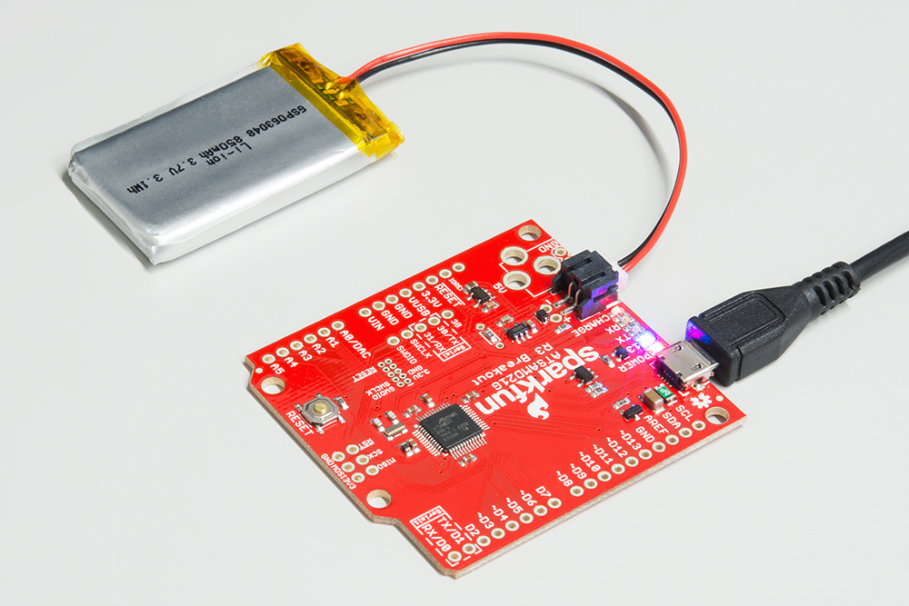
The "Charge" LED should illuminate while the battery is charging, and it should eventually turn off once fully juiced up.
The MCP73831's charge current is configured by a resistor value between 66kΩ and 2kΩ, to charge the battery at a rate between 15mA and 500mA, respectively. By default, the board is configured to charge the battery at around 250mA.
Most batteries shouldn't be charged at a rate over 1C (for example, a 110mAh battery's 1C charge current would be 110mA). If you need to adjust the charge current, we've added pads for a through-hole resistor. This resistor can be added in parallel with the 3.9kΩ resistor already on board, or SJ1 (highlighted below) can be cut on the backside to remove that resistor from the circuit.
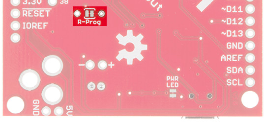
If you need a smaller charge current, SJ1 must be cut, before adding a resistor. Increasing the charge current can be achieved by adding a resistor in parallel. Here are a few resistor value/charge current examples:
| Charge Current (ICharge) | Total Resistance (RProg) | Parallel Resistor |
|---|---|---|
| 40mA | 25kΩ | No, must cut SJ1 |
| 100mA | 10kΩ | No, must cut SJ1 |
| 400mA | 2.5kΩ | 6.9kΩ |
| 500mA | 2kΩ | 4.1kΩ |
The charge current is calculated as:
Depending on the task it's given, the SAMD21's core will usually consume between 3-17mA. There should be plenty of juice left from the 600mA 3.3V regulator to power other sensors or components off the Breakout's 3.3V supply rail.
Each I/O pin can sink up to 10mA and source up to 7mA, with one caveat: each cluster of I/O is limited to sourcing 14mA or sinking 19.5mA. The GPIO clusters are:
| Cluster | GPIO | Cluster Supply (Pin) | Cluster Ground (Pin) |
|---|---|---|---|
| 1 | SWCLK, SWDIO | VDDIN (44) | GND (42) |
| 2 | 30, 31 (USB_HOST_EN, TX_LED) | VDDIN (44) VDDIO (36) | GND (42) GND (35) |
| 3 | D2, D5, D6, D7, D10, D11, D12, D13, D38 SCL, SDA, MISO, SCK, MOSI (USB_D-, USB_D+) | VDDIO (36) VDDIO (17) | GND (35) GND (18) |
| 4 | D0, D1, D3, D4 | VDDIO (17) | GND (18) |
| 5 | A1, A2, A3, A4 D8, D9 | VDDANA (6) | GNDANA (5) |
| 6 | A0, A5, AREF (RX_LED, RTC1, RTC2) | VDDANA (6) | GNDANA (5) |
So, for example, if you're sourcing current to four LEDs tied to pins 0, 1, 3, and 4 (cluster 4), the sum of that current must be less than 14mA (~3.5mA per LED).
Speaking of LEDs, the SAMD21 Dev Breakout has a lot of them: a power indicator, pin 13 "status" LED, USB transmit and receive LED indicators, and a battery charge status indicator.
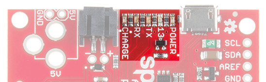
The blue LED driven by the Arduino's pin 13 is actually sourced through an N-channel MOSFET, so less of our precious cluster-current is eaten up. The LED still turns on when you write the pin HIGH and off when pin 13 is LOW.
The RX and TX LEDs indicate activity on the USB serial port while the Arduino is being programmed via bootloader. They are also addressable within an Arduino sketch, using the macros PIN_LED_RXL and PIN_LED_TXL. These LEDs are active-low, so writing the pin HIGH will turn the LED off.
The charge LED is controlled by the board's integrated MCP73831 battery charger. If a battery is connected and 5V supplied (via USB or the external jack), it will illuminate when a battery is being charged and should turn off once fully-charged.
If you really want to step your SAMD21-development game up, consider grabbing an ARM debugger/programmer and interfacing it with the SAMD21's Cortex Debug port.
These pins break out the Cortex Debug Port -- a single-wire debug (SWD) interface -- to a standardized 10-pin, 0.05"-pitch connector. These are polarized/non-polarized female connectors and male connectors available to connecto an ARM programmer's SWD cable.
Any ARM debugger/programmer should work with this port -- just make sure the interface cable is pin-compatible. We highly recommend the awesome, multi-architecture-supporting Atmel JTAG ICE.
This page focuses on the features of the SAMD21 Mini Breakout. No, you're not experiencing Déjà vu, a lot of this information is copied over from the previous section. If you've already learned everything you need to know about your SAMD21 Dev Breakout, skip ahead to the hardware setup section.
We've pinned the Mini Breakout to match -- as much as possible -- our faithful Pro Mini and Pro Micro. The I/O and voltage rails are all broken out to a pair of breadboard-compatible headers. Power can be supplied, and the board can be programmed, through the micro-B USB connector.
Here's an overview of the pin breakouts. For more information, consult our graphical datasheet, which exhaustively shows the capability of each I/O pin, and some of the other features on the board.
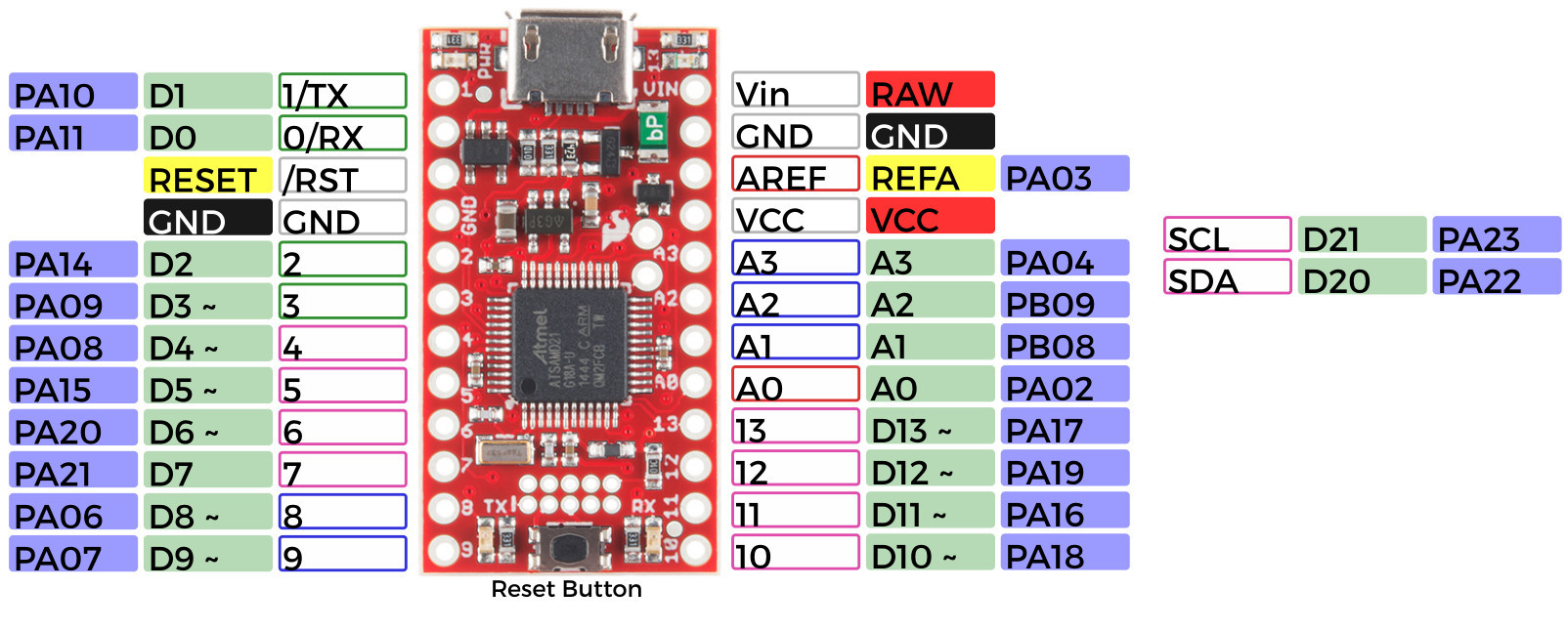
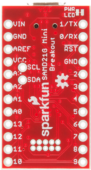
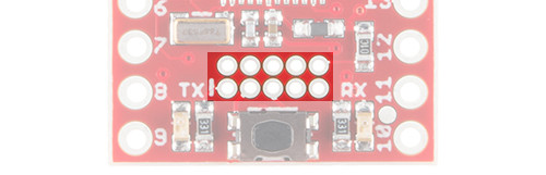
Components on the top side of the board didn't leave room to label each-and-every pin. If you need a quick pin-number reference, flip the board over:
The standard I2C pins -- SDA and SCL -- are broken out to the inner area of the board, and the Single-Wire Debug (SWD) pins -- SWCLK and SWDIO -- are accessible via the 10-pin Cortex Debug port (though you may want to consider leaving those free for debugging).
⚡ 3.3V Logic Levels! When you start interfacing the SAMD21's I/O pins with external sensors and other components, keep in mind that each I/O will produce, at most, 3.3V for a high-level output.
When configured as an input, the maximum input voltage for each I/O is 3.6V (VDD+0.3V). If you're interfacing the SAMD21 with 5V devices, you may need some level shifters in between.
Power can be supplied to the SAMD21 Mini Breakout through either USB or the VIN/GND pins.
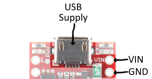
The USB jack is of the micro-B variety, it should work with one of the many USB phone-charging cables you have lying around, or one of our Micro-B cables. You can plug the other end into a computer USB port, or use a USB Wall Adapter. The USB supply input includes a 500mA PTC resettable fuse -- if something on or connected to the breakout fails, it should help protect your supply from damage.
The VIN and GND pins are spaced by a standard 0.1" (2.54mm). If you want an easy way to connect or remove power, our 2.54mm Pitch 2-Pin Screw Terminals play the part well.
If you supply power via the VIN pin, make sure the voltage level is somewhere between 3.5 and 6V. The on-board AP2112K 3.3V regulator is low-noise, low-dropout, and can supply up to 600mA, but has a maximum input voltage of 6V.
Depending on the task it's given, the SAMD21's core will usually consume between 3-17mA. There should be plenty of juice left from the 600mA 3.3V regulator to power other sensors or components off the Breakout's 3.3V supply rail.
Each I/O pin can sink up to 10mA and source up to 7mA, with one caveat: each cluster of I/O is limited to sourcing 14mA or sinking 19.5mA. The GPIO clusters are:
| Cluster | GPIO | Cluster Supply (Pin) | Cluster Ground (Pin) |
|---|---|---|---|
| 1 | SWCLK, SWDIO | VDDIN (44) | GND (42) |
| 2 | 30, 31 (USB_HOST_EN, TX_LED) | VDDIN (44) VDDIO (36) | GND (42) GND (35) |
| 3 | D2, D5, D6, D7, D10, D11, D12, D13, D38 SCL, SDA, MISO, SCK, MOSI (USB_D-, USB_D+) | VDDIO (36) VDDIO (17) | GND (35) GND (18) |
| 4 | D0, D1, D3, D4 | VDDIO (17) | GND (18) |
| 5 | A1, A2, A3, A4 D8, D9 | VDDANA (6) | GNDANA (5) |
| 6 | A0, A5, AREF (RX_LED, RTC1, RTC2) | VDDANA (6) | GNDANA (5) |
So, for example, if you're sourcing current to four LEDs tied to pins 0, 1, 3, and 4 (cluster 4), the sum of that current must be less than 14mA (~3.5mA per LED).
SAMD21 Mini Breakout has four LEDs occupying the corners of the board. There is a power indicator, a pin 13 "status" LED, and USB transmit and receive LED indicators.
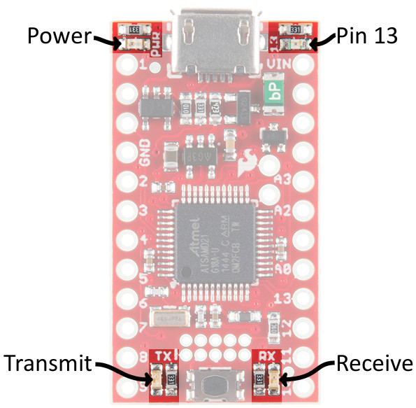
The blue LED driven by the Arduino's pin 13 is actually sourced through an N-channel MOSFET, so less of our precious cluster-current is eaten up. The LED still turns on when you write the pin HIGH and off when pin 13 is LOW. Unfortunately, the MOSFET's gate is floating, so if the Arduino pin is set as an input you may still see the LED turn on.
The RX and TX LEDs -- though not yet fully implemented -- indicate activity on the USB serial port as the Arduino is being programmed via bootloader. They are also addressable within an Arduino sketch, using the macros PIN_LED_RXL and PIN_LED_TXL. These LEDs are active-low, so writing the pin HIGH will turn the LED off.
If you want to step your SAMD21-development game up, consider grabbing an ARM debugger/programmer and interfacing it with the SAMD21's Cortex Debug port.
These pins break out the Cortex Debug Port -- a single-wire debug (SWD) interface -- to a standardized 10-pin, 0.05"-pitch connector. These are polarized/non-polarized female connectors and male connectors available to connecto an ARM programmer's SWD cable.
Any ARM debugger/programmer should work with this port -- just make sure the interface cable is pin-compatible. We highly recommend the awesome, multi-architecture-supporting Atmel JTAG ICE.
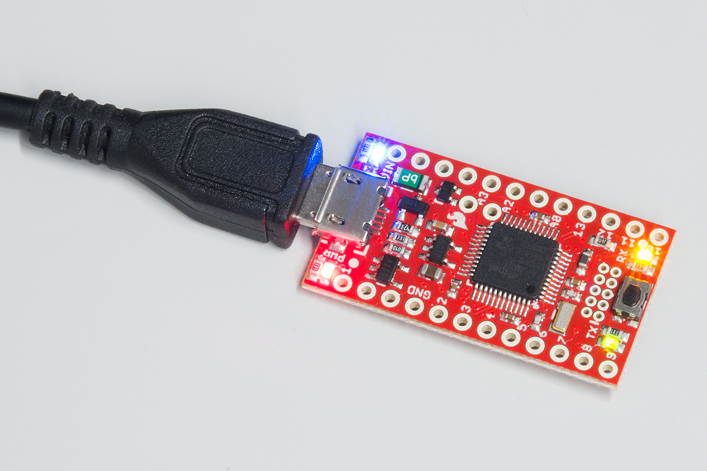
To power the SAMD21 Breakout board, just plug it into a USB port on your computer. The red power LED indicator should immediately turn on, followed shortly-thereafter by a blinking blue LED on pin 13.
You can set the SAMD21 Boards up -- and start programming them -- without connecting anything besides a USB cable, but you're not going to get far without soldering something to them. That something can be headers (male, female, right-angle or more) or just plain-old wire.
If you're using a Mini Breakout, a pair of 12-pin male headers work well to keep the board breadboard-friendly. A 2-pin female header can be soldered to the inner I2C pins -- though you may have to trim the bottom side of the shroud to avoid the ATSAMD21's pins.
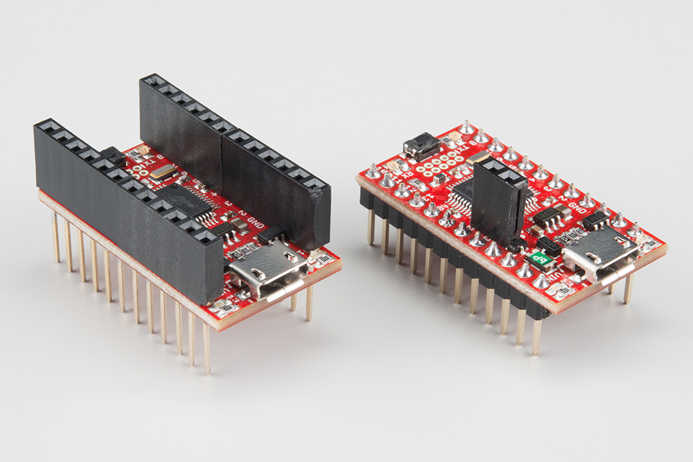
Two pairs of 6-pin stackable headers can also maintain breadboard-compatibility while allowing your to jumper straight out of the board. To use these headers, you'll have to shave a bit of the bottom edge of the shroud to avoid bumping up against the outer LEDs.
If you're using the Dev Breakout, you can keep it Arduino-shield-compatible by soldering a handful of female headers into the 6-, 8-, and 10-pin headers. Then solder some 3-pin male headers into the SPI port.
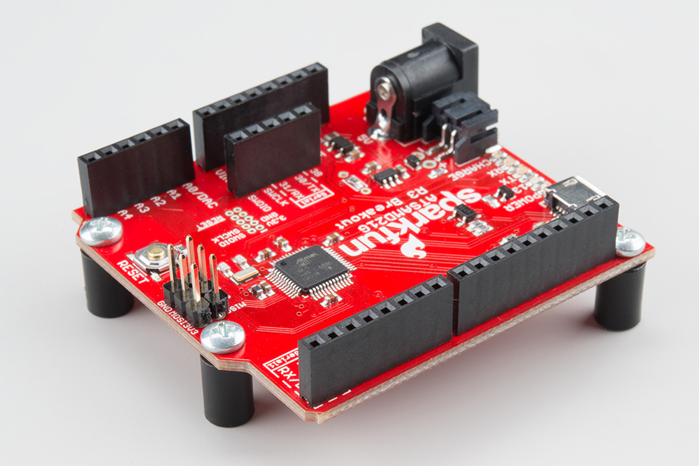
Finish it off by adding a PTH Barrel Jack and a set of standoffs and 1/4" 4-40 screws.
After plugging the board in, Windows will try to search the Internet for drivers. They should automatically install for Windows 10 without any issues.
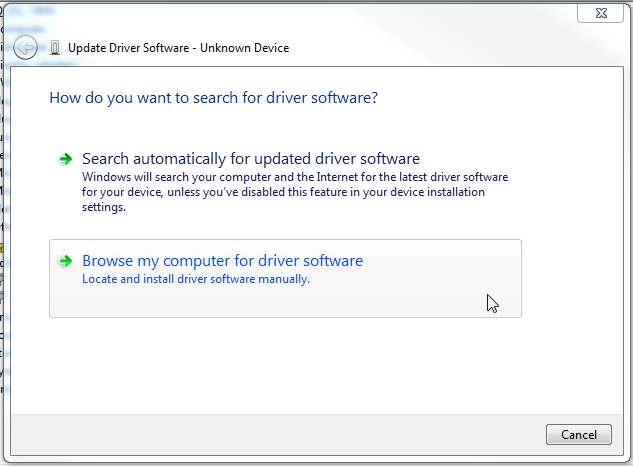
However, if you run into issues, you may need to install the drivers manually. Click the button below to download the drivers from the GitHub Repo.
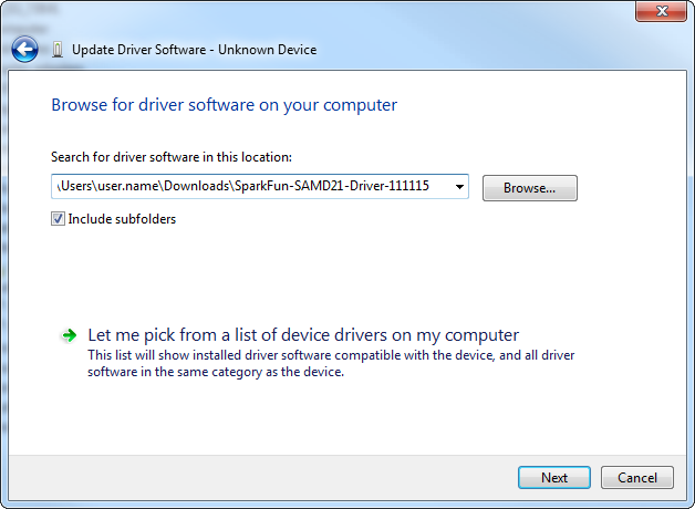
Then follow the steps below to install the drivers:
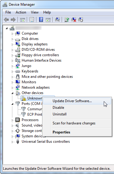
In the Device Manager, expand the "Other devices" tree -- you should see an entry for "Unknown Device", Right-click and select Update Driver Software...
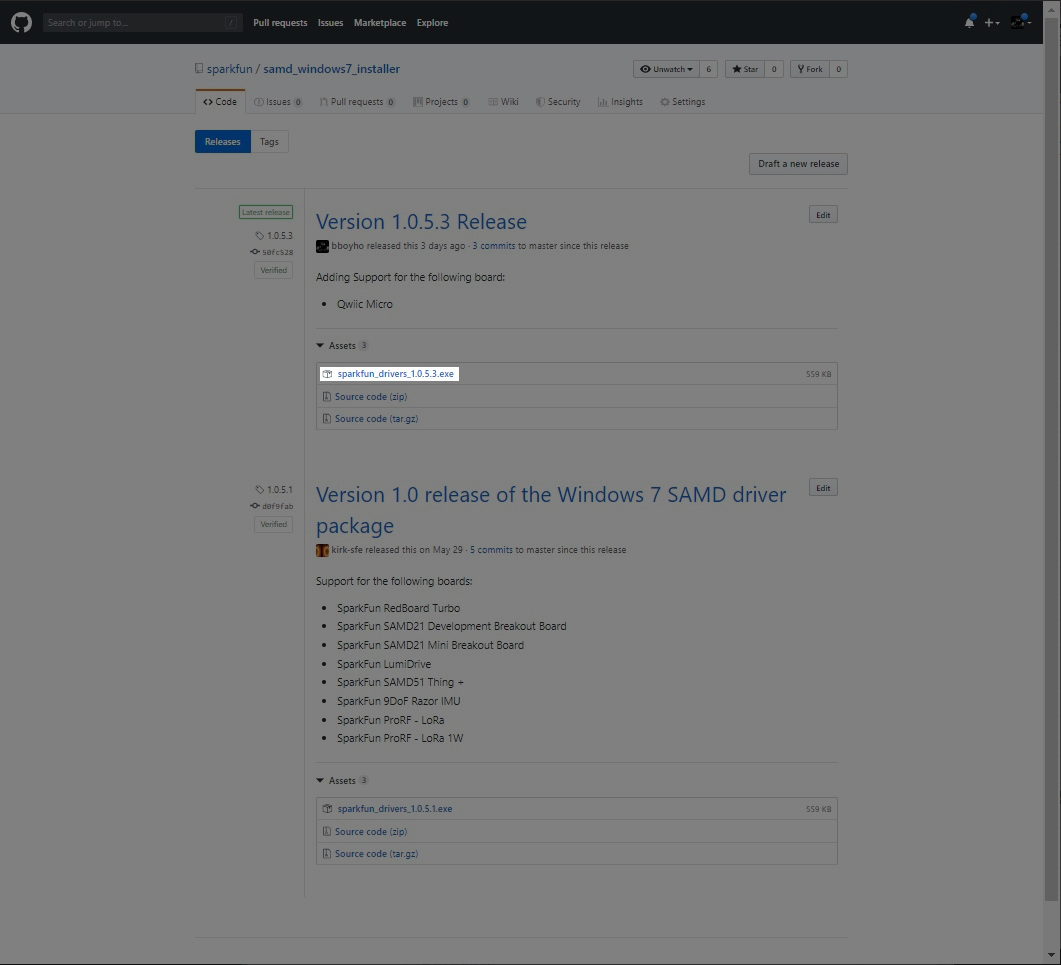
If you are using a Windows 7 OS, you will need to install the SAMD drivers using the SAMD Windows 7 Installer. Head over to the GitHub repo to install the executable.
Scroll down the page to the assets in the Latest release and click on the '.exe to download. The version number may be different depending on the release. The image below shows sparkfun_drivers_1.0.5.3.exe .
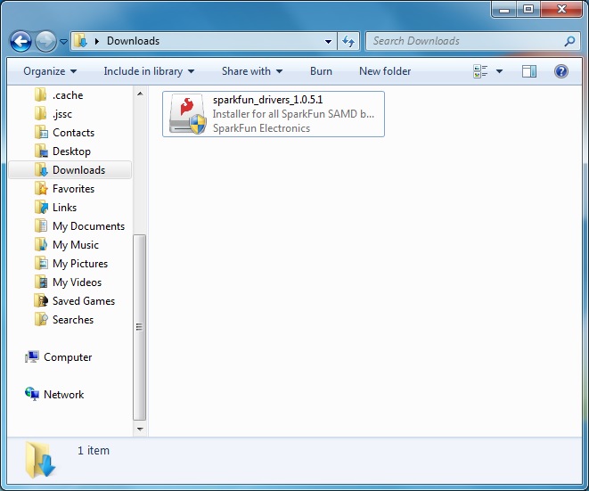
After downloading, click on the executable and follow the prompts to install. The steps to install are the same even though the following images show drivers for v1.0.5.1.
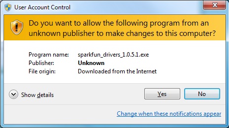
You will receive a warning from Windows. Click yes to continue.
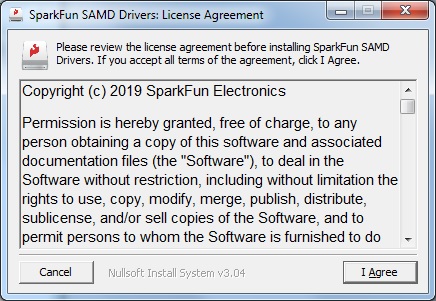
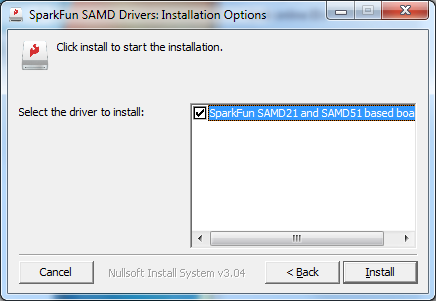
Another window will pop up. Read through the license and click "I Agree".
When ready, hit the Install button.
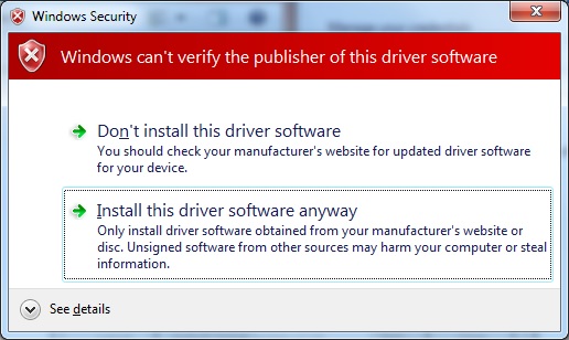
Another window will pop up. Click on "Install this driver software anyway" to continue.
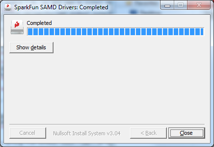
Your Windows 7 will begin installing the driver. This should take a few seconds. When the drivers have installed, hit the "Close" button to exit out of the installer.
Mac and Linux users shouldn't need to download any drivers. The device should show up as a serial port as soon as it's plugged in to your computer.
Update Arduino! This setup requires at least Arduino version 1.6.4 or later. We've tested it on 1.6.5 and the latest version – 1.6.6.
If you're running an older version of Arduino, consider visiting arduino.cc to get the latest, greatest release.
While the SAMD21 alone is powerful enough, what truly makes it special is its growing support in the Arduino IDE. With just a couple click's, copies, and pastes, you can add ARM Cortex-M0+-support to your Arduino IDE. This page will list every step required for getting SparkFun SAMD21 Breakout support into your Arduino IDE.
First, you'll need to install a variety of tools, including low-level ARM Cortex libraries full of generic code, arm-gcc to compile your code, and bossa to upload over the bootloader. These tools come packaged along with Arduino's SAMD board definitions for the Arduino Zero.
To install the Arduino SAMD board definitions, navigate to your board manager (Tools > Board > Boards Manager...), then find an entry for Arduino SAMD Boards (32-bits ARM Cortex-M0+). Select it, and install the latest version (recently updated to 1.6.5).
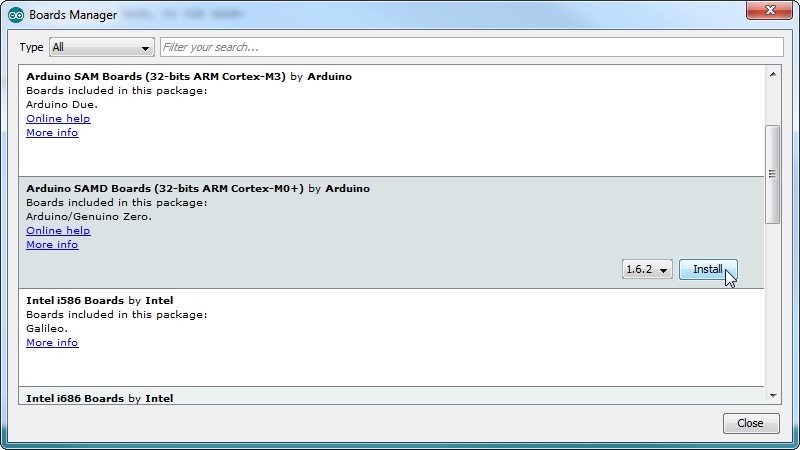
Downloading and installing the tools may take a couple minutes -- arm-gcc in particular will take the longest, it's about 250MB unpacked.
Once installed, Arduino-blue "Installed" text should appear next to the SAMD boards list entry.
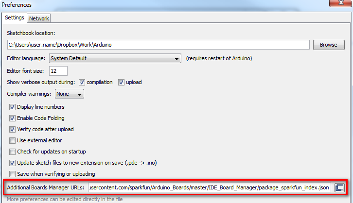
Now that your ARM tools are installed, one last bit of setup is required to add support for the SparkFun SAMD boards. First, open your Arduino preferences (File > Preferences). Then find the Additional Board Manager URLs text box, and paste the below link in:
https://raw.githubusercontent.com/sparkfun/Arduino_Boards/main/IDE_Board_Manager/package_sparkfun_index.json
Then hit "OK", and travel back to the Board Manager menu. You should (but probably won't) be able to find a new entry for SparkFun SAMD Boards. If you don't see it, close the board manager and open it again. ¯\_(ツ)_/¯.
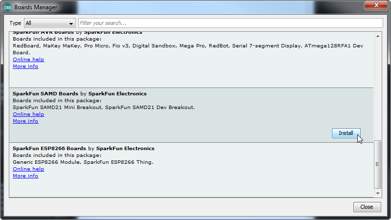
This installation should be much faster; you've already done the heavy lifting in the previous section.
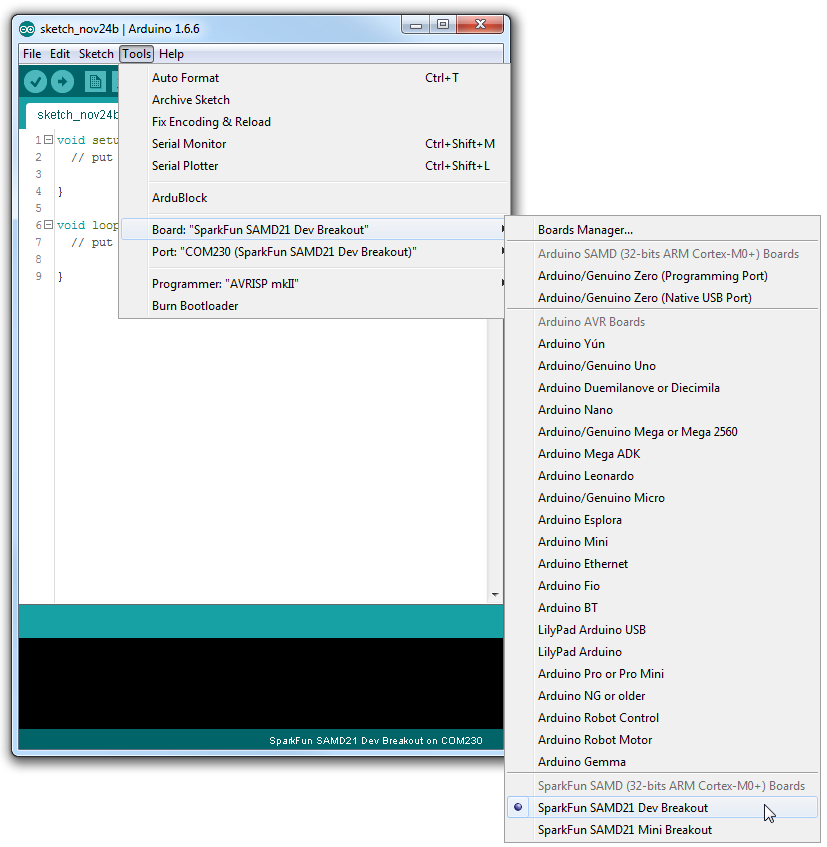
Once the board is installed, you should see two new entries in your Tools > Board list: one for the Mini Breakout and one for the Dev. Select your SparkFun SAMD21 Board.
Finally, select your SAMD21 Board's port. Navigate back up to the Tool > Port menu. The port menu may magically know which of your ports (if you have more than one) are the SAMD21 board. On a Windows machine, the serial port should come in the form of "COM#". On a Mac or Linux machine, the port will look like "/dev/cu.usbmodem####".
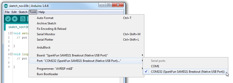
Once you find it, select it!
As with any development board, if you can blink an LED, you're well on your way to controlling the rest of the world. Since the SAMD21 Boards have 3 user-controllable LEDs, let's blink them all!
The RX and TX LEDs are on pins 25 and 26, respectively, a couple pre-defined macros (PIN_LED_RXL and PIN_LED_TXL) can be used to access those pins, just in case you forget the numbers.
Here's a quick example sketch to blink the LEDs and make sure your environment is properly set up. Copy and paste from below, and upload!
language:c
const int BLUE_LED = 13; // Blue "stat" LED on pin 13
const int RX_LED = PIN_LED_RXL; // RX LED on pin 25, we use the predefined PIN_LED_RXL to make sure
const int TX_LED = PIN_LED_TXL; // TX LED on pin 26, we use the predefined PIN_LED_TXL to make sure

bool ledState = LOW;

void setup()
{
  pinMode(BLUE_LED, OUTPUT);
  pinMode(RX_LED, OUTPUT);
  pinMode(TX_LED, OUTPUT);
  digitalWrite(RX_LED, HIGH);
  digitalWrite(TX_LED, HIGH);
  digitalWrite(BLUE_LED, LOW);
}

void loop()
{
  digitalWrite(RX_LED, LOW); // RX LED on
  delay(333);
  digitalWrite(RX_LED, HIGH); // RX LED off
  digitalWrite(TX_LED, LOW); // TX LED on
  delay(333);
  digitalWrite(TX_LED, HIGH); // TX LED off
  digitalWrite(BLUE_LED, HIGH); // Blue LED on
  delay(333);
  digitalWrite(BLUE_LED, LOW); // Blue LED off
}
After hitting the "Upload" button, wait a handful of seconds while the code compiles and sends. While the code uploads, you should see the yellow and green LEDs flicker.
Upload Troubles: If you see a No device found on cu.usbmodem#### error, try uploading once again and it should succeed.
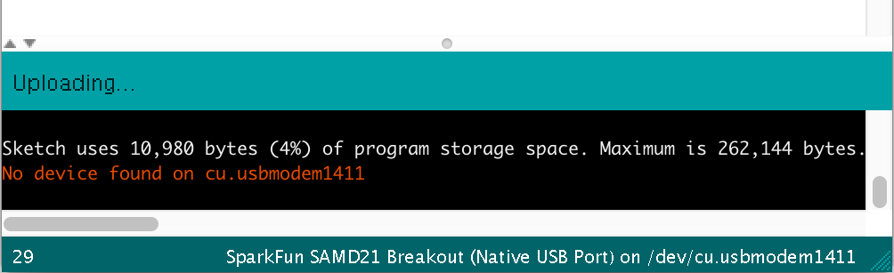
This issue has been most noticeable on Macs. After resetting the board into the bootloader, the delay before attempting an upload isn't long enough. After the first upload try, you should see the yellow "RX" LED illuminate – usually indicating the board has reset into bootloader mode. Another upload try should take.
Until solved, you may have to deal with either double-upload-clicking, or resetting the board into bootloader before uploading.
If your SAMD21 board still won't take your code, consult our Troubleshooting section.
Once you've verified that the IDE is all set up, you can start exploring the world of the ATSAMD21! Continue on for a few examples, which help show what makes the SAMD21 unique.
One of the SAMD21's most exciting features is SERCOM -- its multiple, configurable serial ports. The Arduino IDE equips the SAMD21 with two hardware serial ports, by default, plus a third "USB serial port" for communicating between the serial monitor.
Each of these serial ports has a unique Serial object which you'll refer to in code:
| Serial Object | Serial Port | RX Pin | TX Pin |
|---|---|---|---|
SerialUSB | USB Serial (Serial Monitor) | ||
Serial | Hardware Serial Port 0 | 31 | 30 |
Serial1 | Hardware Serial Port 1 | 0 | 1 |
There are a couple critical things to notice here. First of all, if you're trying to use the Serial Monitor to debug, you'll need to use SerialUSB.begin(<baud>) and SerialUSB.print(). (Thankfully find/replace exists for adjusting example code.)
Also, the Serial USB port isn't broken out on the Mini Breakout. If you want to use the pins 0/1 serial port, you'll need to replace Serial calls with Serial1.
Here's a quick example demonstrating the differences between Serial Monitor and Serial1. It is designed to route data from Serial1 to the Serial Monitor, and vice-versa.
language:c
void setup()
{
  SerialUSB.begin(9600); // Initialize Serial Monitor USB
  Serial1.begin(9600); // Initialize hardware serial port, pins 0/1

  while (!SerialUSB) ; // Wait for Serial monitor to open

  // Send a welcome message to the serial monitor:
  SerialUSB.println("Send character(s) to relay it over Serial1");
}

void loop()
{
  if (SerialUSB.available()) // If data is sent to the monitor
  {
    String toSend = ""; // Create a new string
    while (SerialUSB.available()) // While data is available
    {
      // Read from SerialUSB and add to the string:
      toSend += (char)SerialUSB.read();
    }
    // Print a message stating what we're sending:
    SerialUSB.println("Sending " + toSend + " to Serial1");

    // Send the assembled string out over the hardware
    // Serial1 port (TX pin 1).
    Serial1.print(toSend);
  }

  if (Serial1.available()) // If data is sent from device
  {
    String toSend = ""; // Create a new string
    while (Serial1.available()) // While data is available
    {
      // Read from hardware port and add to the string:
      toSend += (char)Serial1.read();
    }
    // Print a message stating what we've received:
    SerialUSB.println("Received " + toSend + " from Serial1");
  }
}
Then try typing something into the serial monitor. Even with nothing connected to the hardware serial port, you should see what you typed echoed back at you.
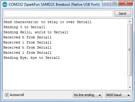
You can further test this sketch out by connecting an 3.3V FTDI Basic or any other serial device to the SAMD21's pins 0 (RX) and 1 (TX). You'll need IC hooks for a quick temporary connection. Otherwise, you'll need to solder pins or wires to the board. By opening up a serial terminal, any data sent from the FTDI should end up in your Arduino Serial Monitor, and data sent to your Arduino Serial Monitor will route over to the FTDI. Here's a table that shows what pins to connect together.
| SAMD21 Pins | 3.3V FTDI (or any USB-to-Serial Converter) Pins |
|---|---|
| 1/TX | RXI |
| 0/RX | TXO |
| GND | GND |
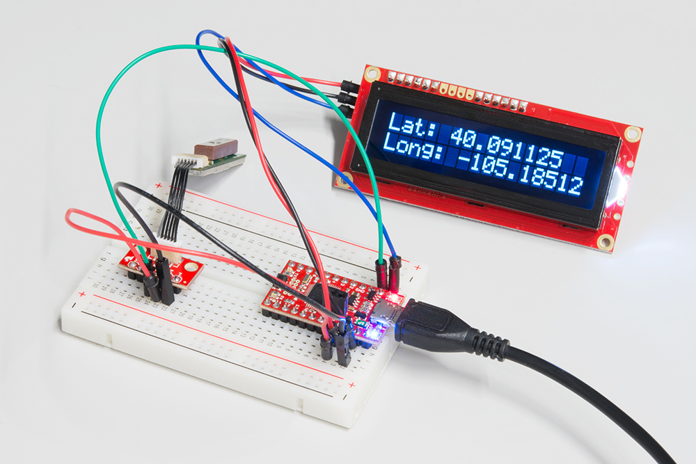
To take it even further, try a GPS module to test RX, and a Serial LCD to test TX.
While it still has PWM-based "analog outputs", the SAMD21 also features true analog output in the form of a digital-to-analog converter (DAC). This module can produce an analog voltage between 0 and 3.3V. It can be used to produce audio with more natural sound, or as a kind of "digital potentiometer" to control analog devices.
The DAC is only available on the Arduino pin A0, and is controlled using analogWrite(A0, <value>). The DAC can be set up to 10-bit resolution (make sure to call analogWriteResolution(10) in your setup), which means values between 0 and 1023 will set the voltage to somewhere between 0 and 3.3V.
In addition to the DAC, the SAMD21's ADC channels also stand apart from the ATmega328: they're equipped with up to 12-bit resolution. That means the analog input values can range from 0-4095, representing a voltage between 0 and 3.3V. To use the ADC's in 12-bit mode, make sure you call analogReadResolution(12) in your setup.
Here's an example that demonstrates both the 10-bit DAC and the 12-bit ADC. To set the experiment up, connect A0 to A1 -- we'll drive A0 with an analog voltage, then read it with A1. It's the simplest circuit we've ever put in a tutorial:

Then copy and paste the code below into your Arduino IDE, and upload!
language:c
// Connect A0 to A1, then open the Serial Plotter.

#define DAC_PIN A0 // Make code a bit more legible

float x = 0; // Value to take the sin of
float increment = 0.02;  // Value to increment x by each time
int frequency = 440; // Frequency of sine wave

void setup()
{
  analogWriteResolution(10); // Set analog out resolution to max, 10-bits
  analogReadResolution(12); // Set analog input resolution to max, 12-bits

  SerialUSB.begin(9600);
}

void loop()
{
  // Generate a voltage value between 0 and 1023.
  // Let's scale a sin wave between those values:
  // Offset by 511.5, then multiply sin by 511.5.
  int dacVoltage = (int)(511.5 + 511.5 * sin(x));
  x += increment; // Increase value of x

  // Generate a voltage between 0 and 3.3V.
  // 0= 0V, 1023=3.3V, 512=1.65V, etc.
  analogWrite(DAC_PIN, dacVoltage);

  // Now read A1 (connected to A0), and convert that
  // 12-bit ADC value to a voltage between 0 and 3.3.
  float voltage = analogRead(A1) * 3.3 / 4096.0;
  SerialUSB.println(voltage); // Print the voltage.
  delay(1); // Delay 1ms
}
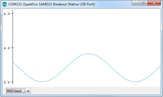
This sketch produces a sine wave output on A0, with values ranging from 0 to 3.3V. Then it uses A1 to read that output into its 12-bit ADC, and convert it into a voltage between 0 and 3.3V.
You can, of course, open the serial monitor to view the voltage values stream by. But if the the sine wave is hard to visualize through text, check out Arduino's new Serial Plotter, by going to Tools > Serial Plotter.
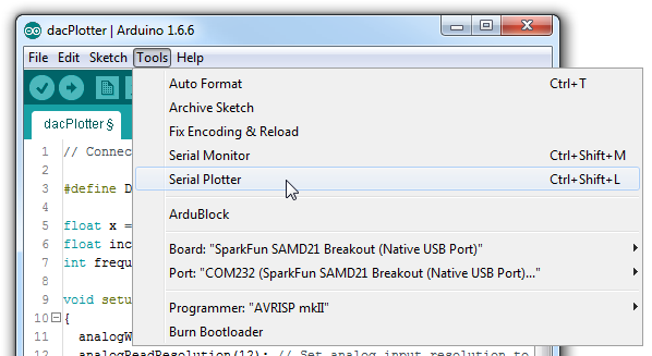
And take in the majesty of that sine wave.
Both of the SAMD21 boards have a 32.768kHz crystal connected to their external clock source, and the chips themselves have built-in features that make time-keeping with an RTC super-easy.
RTCs are a critical component for any project that needs a precise idea of how much time has passed. There are all sorts of applications that can take advantage of accurate time-keeping, including web security, data logging, and of course DIY alarm clocks!
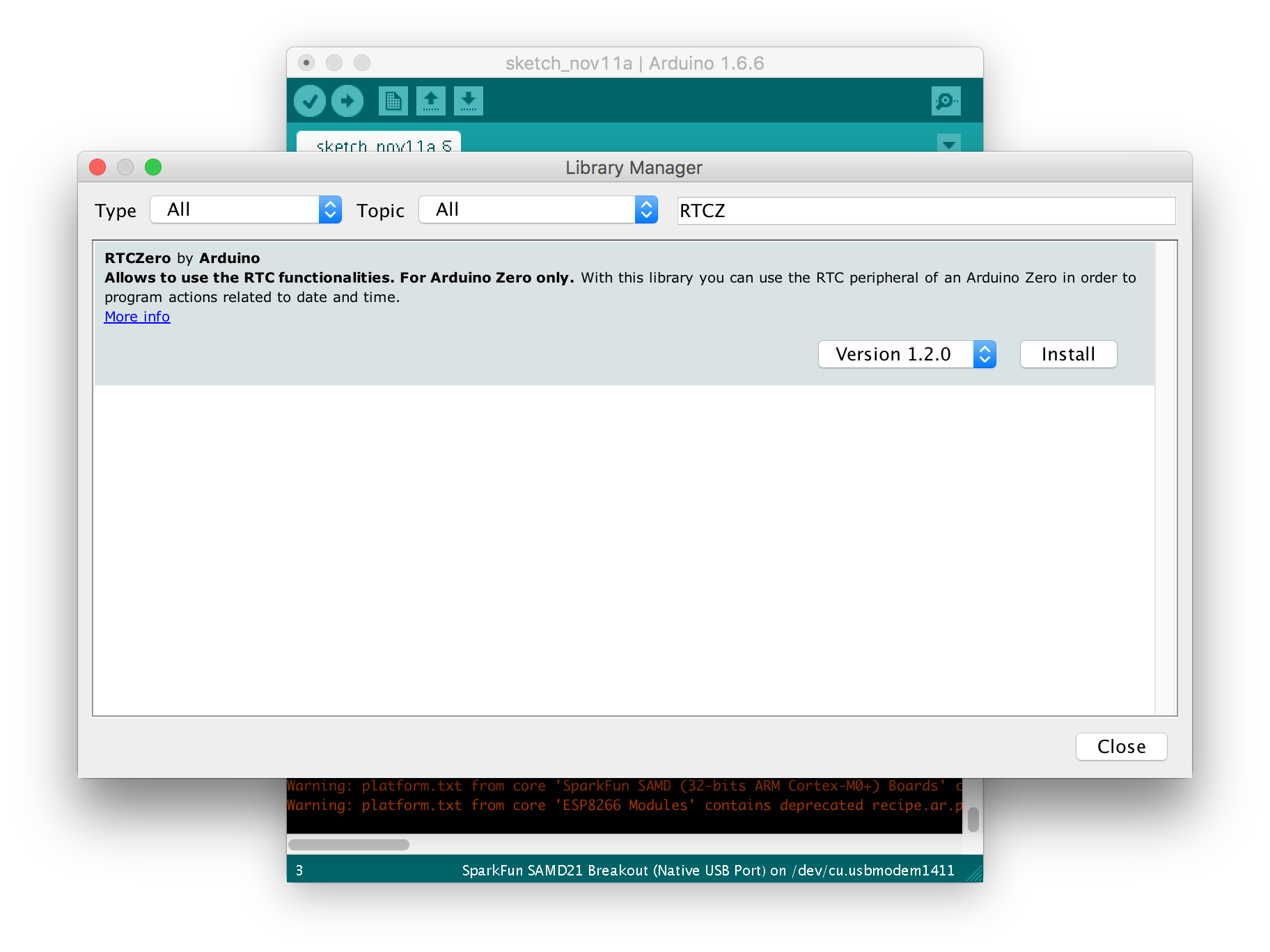
To use the RTC in Arduino, you'll first have to install the RTCZero library. This library can be downloaded using Arduino's library manager.
In Arduino, navigate to Sketch > Include Library > Manage Libraries.... In the library manager that pops up, search for "RTCZero", and install the latest version.
Once you've installed the RTCZero library, copy and paste our RTCSerialAlarm sketch from below. No extra components are required, though it's easy to imagine adding displays of all varieties, and/or buttons to set the time and alarm.
language:c
#include <RTCZero.h> // Include RTC library - make sure it's installed!

RTCZero rtc; // Create an RTC object
byte lastSecond = 60;
byte alarmMinute = 1; // Minutes after clock starts to sound alarm
bool alarmTriggered = false;

void setup()
{
  SerialUSB.begin(9600);
  while (!SerialUSB) ; // Wait for Serial monitor to open

  byte hour = prompt("Hour", 0, 23); // Get the hour
  byte minute = prompt("Minute", 0, 59); // Get the minute
  byte second = prompt("Second", 0, 59); // Get the second
  byte day = prompt("Day", 0, 31); // Get the day
  byte month = prompt("Month", 0, 12); // Get the month
  byte year = prompt("Year (YY)", 0, 99); // Get the year

  SerialUSB.println("Press any key to begin");
  while (!SerialUSB.available()) ; // Wait for keypress to start clock

  rtc.begin(); // To use the RTC, first begin it
  rtc.setTime(hour, minute, second); // Then set the time
  rtc.setDate(day, month, year); // And the date
  SerialUSB.println("RTC Started!");

  SerialUSB.println("Setting alarm for " + String(alarmMinute) + " minute(s).");
  SerialUSB.println();
  byte alarmHour = hour + ((alarmMinute + minute) / 60);
  alarmMinute = (alarmMinute + minute) % 60;

  // To set an alarm, use the setAlarmTime function.
  rtc.setAlarmTime(alarmHour, alarmMinute, second);
  // After the time is set, enable the alarm, configuring
  // which time values you want to trigger the alarm
  rtc.enableAlarm(rtc.MATCH_HHMMSS); // Alarm when hours, minute, & second match
  // When the alarm triggers, alarmMatch will be called:
  rtc.attachInterrupt(alarmMatch);
}

void loop()
{
  // If the second value is different:
  if (lastSecond != rtc.getSeconds())
  {
    printTime(); // Print the time
    lastSecond = rtc.getSeconds(); // Update lastSecond

    if (alarmTriggered) // If the alarm has been triggered
    {
      SerialUSB.println("Alarm!"); // Print alarm!
    }
  }
}

void printTime()
{
  // Use rtc.getDay(), .getMonth(), and .getYear()
  // To get the numerical values for the date.
  SerialUSB.print(rtc.getDay()); // Print day
  SerialUSB.print("/");
  SerialUSB.print(rtc.getMonth()); // Print Month
  SerialUSB.print("/");
  SerialUSB.print(rtc.getYear()); // Print year
  SerialUSB.print("\t");

  // Use rtc.getHours, .getMinutes, and .getSeconds()
  // to get time values:
  SerialUSB.print(rtc.getHours()); // Print hours
  SerialUSB.print(":");
  if (rtc.getMinutes() < 10)
    SerialUSB.print('0'); // Pad the 0
  SerialUSB.print(rtc.getMinutes()); // Print minutes
  SerialUSB.print(":");
  if (rtc.getSeconds() < 10)
    SerialUSB.print('0'); // Pad the 0
  SerialUSB.print(rtc.getSeconds()); // Print seconds
  SerialUSB.println();
}

void alarmMatch()
{
  // This function is called when the alarm values match
  // and the alarm is triggered.
  alarmTriggered = true; // Set the global triggered flag
}

// Helper function to prompt for a value, and return
// it if it's within a valid range.
byte prompt(String ask, int mini, int maxi)
{
  SerialUSB.print(ask + "? ");
  while (!SerialUSB.available()) ; // Wait for numbers to come in
  byte rsp = SerialUSB.parseInt();
  if ((rsp >= mini) && (rsp <= maxi))
  {
    SerialUSB.println(rsp);
    return rsp;
  }
  else
  {
    SerialUSB.println("Invalid.");
    return mini;
  }
}
Once uploaded, open the serial monitor, and follow along with the prompts to enter the time and date. Then press another key to start running the clock!
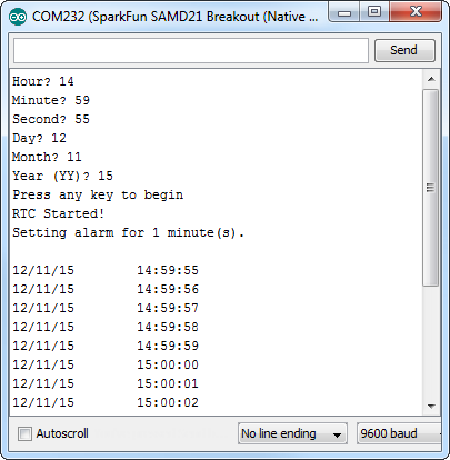
After a minute, the alarm will trigger. You'll need to call disableAlarm() to turn it off. How about adding a button to disable it!?
For help using the RTCZero library, read through the comments in the sketch, or consult Arduino's reference page.
If you've used an Arduino Leonardo or SparkFun Pro Micro, you may be familiar with some of the common issues that arise when a USB-based chip also doubles as its own USB-to-Serial converter and programmer. This page lists a few tips, tricks, and work-arounds if an issue is getting in the way of your ATSAMD21 exploring.
This isn't necessarily troubleshooting, but this is a handy tool for any issues you may encounter. The ATSAMD21's USB bootloader is what allows us to load code over a simple USB interface -- it's a small bit of firmware that lives "beneath" your Arduino sketch. The Arduino IDE should reset your SAMD21 board into bootloader mode milliseconds before it begins uploading new code.
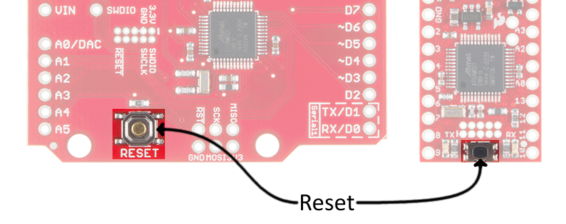
You can manually enter bootloader mode by rapidly double-tapping the reset button. (After hitting the reset button once, you have about half a second to hit it again to enter bootloader mode.)
Earlier versions of the SAMD21 Mini/Dev breakout will indicate that it has entered bootloader mode when the yellow RX LED lights up and remains illuminated. Current versions will indicate that it has entered bootloader mode when the blue LED on pin D13 begins pulsing. The chip will remain in bootloader mode until power cycles or reset is hit again (once).
One global issue to be aware of is that each SAMD21 Board appears to your computer as two USB devices, and your computer will assign two different port numbers to your SAMD21 Board -- one for the bootloader, the other for the sketch.
When you hit upload, the Arduino IDE will reset your SAMD21 board, then look for a new COM port to enumerate on your computer, which it assumes is the bootloader device. After some time waiting, if it doesn't see a new port appear, Arduino will try sending code to the port you've selected.
If your SAMD21 board is plugged in -- power LED illuminated -- but it isn't appearing in your Arduino port list, first of all, make sure you have the drivers installed (Windows computers only). Then follow these steps to see if you can get the port back:
If a sketch upload is taking longer than usual, or fails entirely, try resetting into the bootloader and uploading directly there. If the SAMD21 is in bootloader mode, you may need to re-select your port -- this time selecting the bootloader port.
Closing the serial monitor before uploading may also make for more reliable uploading.
If resetting the Arduino IDE, or forcing the SAMD21 Board into bootloader mode isn't helping to solve your problem, it may be an issue we haven't encountered yet. Please contact our technical support team, and we'll be happy to help!
There is a wealth of information out there, whether you're looking for datasheets, schematics, or design files. Here are a few links you might find handy:
It's a brave new world out there -- Arduinos and ARMs working together! What are you going to create with your powerful, new SAMD21 Breakout? Looking for more SAMD21 fun? Check out these related tutorials.
Looking for some inspiration, check out these tutorials!
Or check out these related blog posts.
learn.sparkfun.com | CC BY-SA 3.0 | SparkFun Electronics | Niwot, Colorado