SAMD21 Mini/Dev Breakout Hookup Guide
 jimblom
 SAMD21 Dev Breakout Overview
Before we get into programming the SAMD21, this page briefly covers some of the features built into the SAMD21 Dev Breakout. If you're reading this guide with a mind toward the Mini Breakout, consider skipping ahead to the Mini Breakout overview.
I/O Pins
If you've used any Arduino before, this pinout shouldn't surprise you -- the layout meets the Arduino 1.0 footprint standard, including a separate SPI header and additional I2C header. For a quick reference, consult our graphical datasheet, which exhaustively shows the capability of each I/O pin and some of the other features on the board.
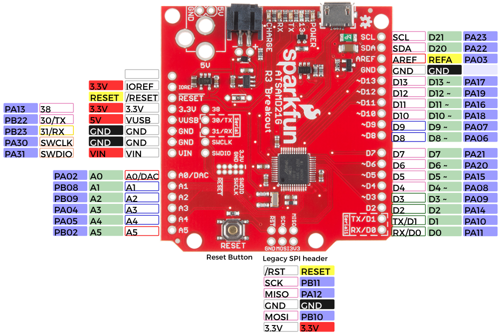
All PWM-capable pins are indicated with a tilde (~) adjacent to the pin-label. Speaking of "analog output", true analog output is available on the A0 pin -- indicated with a shared DAC label.
In addition to the standard I/O footprints, the board also breaks out a few additional pins towards the inside of the board. These pins can be referenced in Arduino by the adjacent silkscreen number (30, 31, and 38).
The Cortex Single-Wire Debugger (SWD) pins -- SWCLK and SWDIO -- don't have Arduino-style reference numbers, though they can be used as GPIO pins.
⚡ 3.3V Logic Levels! When you start interfacing the SAMD21's I/O pins with external sensors and other components, keep in mind that each I/O will produce, at most, 3.3V for a high-level output.
When configured as an input, the maximum input voltage for each I/O is 3.6V (VDD+0.3V). If you're interfacing the SAMD21 with 5V devices, you may need some level shifters in between.
Supplying Power
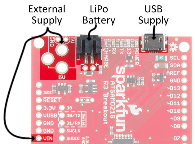
Power can be supplied to the SAMD21 Breakout through either USB, a single-cell (3.7-4.2V) lithium-polymer battery, or an external 5V source. Each of the power supply inputs are available on the top edge of the board (the VIN pin on the power header can also be used).
USB Power
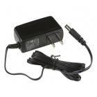
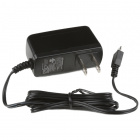
The USB jack is of the micro-B variety. It should work with one of the many USB phone-charging cables you have lying around, or one of our Micro-B cables. You can plug the other end into a computer USB port, or use a USB Wall Adapter. The USB supply input includes a 500mA PTC resettable fuse -- if something on or connected to the breakout fails, it should help protect your supply from damage.

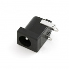
The unpopluated supply input fits our PTH Barrel Jack connector, which would go well with a 5V, Center-Positive Wall Adapter.
Find out more about powering the SAMD21 off a lithium-polymer battery -- and charging that battery -- in the LiPo charger section below.
The on-board AP2112K 3.3V regulator is low-noise, low-dropout, and can supply up to 600mA, but has a maximum input voltage of 6V. Try not to use any supply larger than 5V.
Single-Cell Lithium-Polymer (LiPo) Battery Charger
The SAMD21 touts many low-power features, so using it in battery-powered projects should be a common occurence. We've integrated our standard 2-pin JST connector, and a single-cell USB battery charger into the board. Any of our single-cell lithium polymer batteries can be used to power the board.

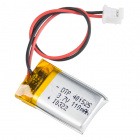


Lithium Ion Battery - 1Ah
PRT-13813To charge the battery, simply connect USB or a 5V supply while the battery is also connected.
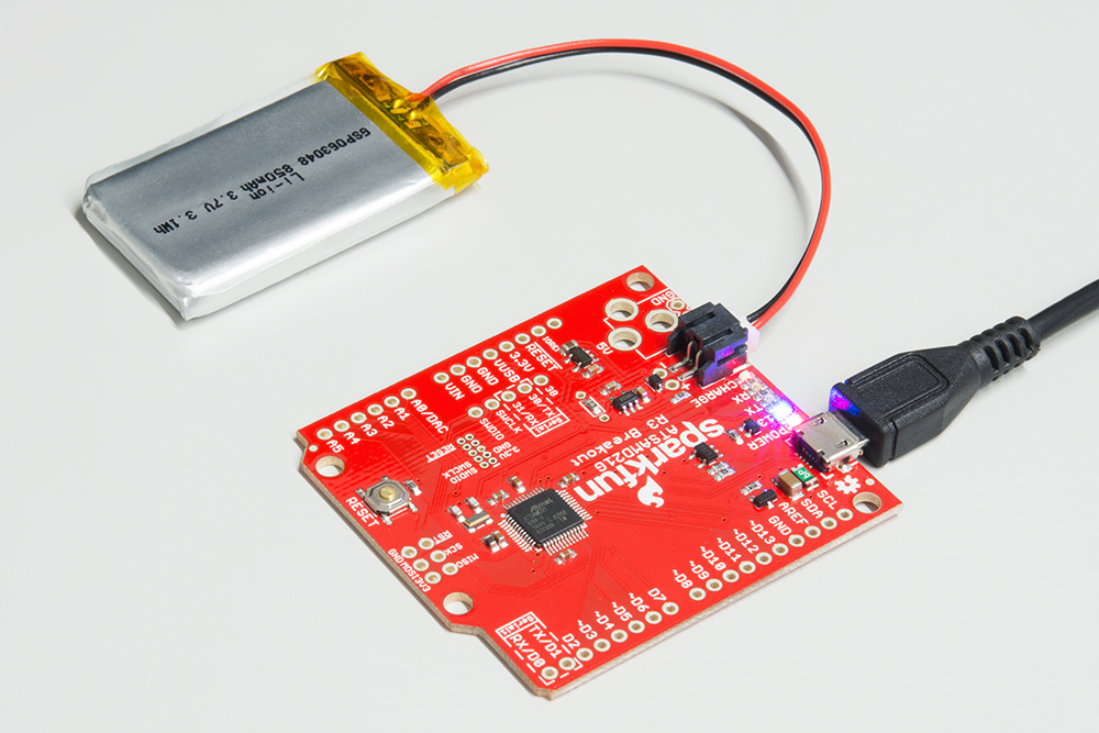
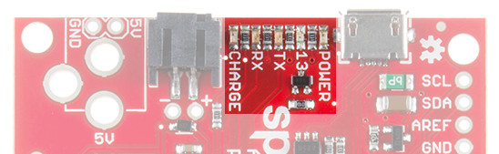
The "Charge" LED should illuminate while the battery is charging, and it should eventually turn off once fully juiced up.
Configuring Battery Charge Current
The MCP73831's charge current is configured by a resistor value between 66kΩ and 2kΩ, to charge the battery at a rate between 15mA and 500mA, respectively. By default, the board is configured to charge the battery at around 250mA.
Most batteries shouldn't be charged at a rate over 1C (for example, a 110mAh battery's 1C charge current would be 110mA). If you need to adjust the charge current, we've added pads for a through-hole resistor. This resistor can be added in parallel with the 3.9kΩ resistor already on board, or SJ1 (highlighted below) can be cut on the backside to remove that resistor from the circuit.
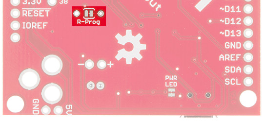
If you need a smaller charge current, SJ1 must be cut, before adding a resistor. Increasing the charge current can be achieved by adding a resistor in parallel. Here are a few resistor value/charge current examples:
| Charge Current (ICharge) | Total Resistance (RProg) | Parallel Resistor |
|---|---|---|
| 40mA | 25kΩ | No, must cut SJ1 |
| 100mA | 10kΩ | No, must cut SJ1 |
| 400mA | 2.5kΩ | 6.9kΩ |
| 500mA | 2kΩ | 4.1kΩ |
The charge current is calculated as:
RProg is the total programming resistor resistance, which may include the 3.9kΩ resistor in parallel.
Current Capabilities
Depending on the task it's given, the SAMD21's core will usually consume between 3-17mA. There should be plenty of juice left from the 600mA 3.3V regulator to power other sensors or components off the Breakout's 3.3V supply rail.
Each I/O pin can sink up to 10mA and source up to 7mA, with one caveat: each cluster of I/O is limited to sourcing 14mA or sinking 19.5mA. The GPIO clusters are:
| Cluster | GPIO | Cluster Supply (Pin) | Cluster Ground (Pin) |
|---|---|---|---|
| 1 | SWCLK, SWDIO | VDDIN (44) | GND (42) |
| 2 | 30, 31 (USB_HOST_EN, TX_LED) | VDDIN (44) VDDIO (36) | GND (42) GND (35) |
| 3 | D2, D5, D6, D7, D10, D11, D12, D13, D38 SCL, SDA, MISO, SCK, MOSI (USB_D-, USB_D+) | VDDIO (36) VDDIO (17) | GND (35) GND (18) |
| 4 | D0, D1, D3, D4 | VDDIO (17) | GND (18) |
| 5 | A1, A2, A3, A4 D8, D9 | VDDANA (6) | GNDANA (5) |
| 6 | A0, A5, AREF (RX_LED, RTC1, RTC2) | VDDANA (6) | GNDANA (5) |
So, for example, if you're sourcing current to four LEDs tied to pins 0, 1, 3, and 4 (cluster 4), the sum of that current must be less than 14mA (~3.5mA per LED).
LEDs
Speaking of LEDs, the SAMD21 Dev Breakout has a lot of them: a power indicator, pin 13 "status" LED, USB transmit and receive LED indicators, and a battery charge status indicator.
Status LED
The blue LED driven by the Arduino's pin 13 is actually sourced through an N-channel MOSFET, so less of our precious cluster-current is eaten up. The LED still turns on when you write the pin HIGH and off when pin 13 is LOW.
Serial UART LEDs
The RX and TX LEDs indicate activity on the USB serial port while the Arduino is being programmed via bootloader. They are also addressable within an Arduino sketch, using the macros PIN_LED_RXL and PIN_LED_TXL. These LEDs are active-low, so writing the pin HIGH will turn the LED off.
Charge LED
The charge LED is controlled by the board's integrated MCP73831 battery charger. If a battery is connected and 5V supplied (via USB or the external jack), it will illuminate when a battery is being charged and should turn off once fully-charged.
Cortex SWD Debug Port
If you really want to step your SAMD21-development game up, consider grabbing an ARM debugger/programmer and interfacing it with the SAMD21's Cortex Debug port.
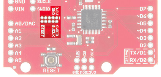
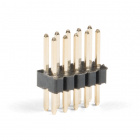
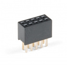
These pins break out the Cortex Debug Port -- a single-wire debug (SWD) interface -- to a standardized 10-pin, 0.05"-pitch connector. These are polarized/non-polarized female connectors and male connectors available to connecto an ARM programmer's SWD cable.
Any ARM debugger/programmer should work with this port -- just make sure the interface cable is pin-compatible. We highly recommend the awesome, multi-architecture-supporting Atmel JTAG ICE.