RETIRED - Exploring XBees and XCTU
This Tutorial is Retired!
This tutorial covers concepts or technologies that are no longer current. It's still here for you to read and enjoy, but may not be as useful as our newest tutorials.
View the updated tutorial: Exploring XBees and XCTU
 jimblom
Drivers and Assembly
The USB-based XBee Explorers all operate using an FTDI FT231X chip, which converts serial to USB and vice-versa. This is one of our favorite chips because it supports all computer platforms and it's easy to work with. If this is the first FTDI chip you've ever connected to your computer (it probably won't be your last), there is some driver installation to get out of the way.
We've written a tutorial detailing How to Install FTDI Drivers tutorial. So go ahead and plug your USB Explorer into your computer, and head on to either the Windows, Mac, or Linux section there. (Ignore the final steps, where Arduino software is invoked.)
Regardless of whether you're on Mac or Windows, once your Explorer's drivers are installed it will be assigned a unique port number. Take note of that port number, as you'll need it on the next pages.
Basic Assembly: Plug In an XBee!
Time to "assemble" the XBee Explorer. Grab your XBee of choice. Notice how it has a flat edge and a more angular/diagonal edge? Match that footprint up to the white lines on your XBee Explorer, and carefully insert!
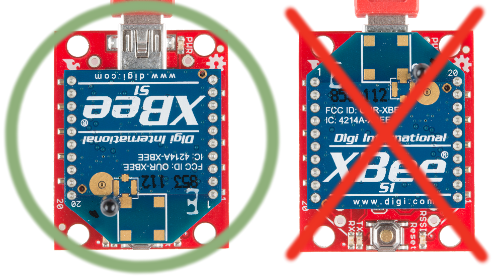
Take care not to bend any of the XBee pins -- be gentle when you're plugging it in. (And be even more careful if you're removing it!)
Nice work! You've assembled the XBee Explorer. You're ready for the next step. Or, if you're a power user, looking to get the most out of your explorer, you can check out the more "advanced" assembly below.
Advanced Assembly (Totally Optional)
For most basic-use cases, all Explorer boards should be good-to-go once you've installed drivers. If you want to use any of the XBee's I/O pins, you can solder male headers to the 0.1"-pitch pins inside the XBee headers. This will allow you to plug the board into a breadboard, so you can wire other components up to the XBee.
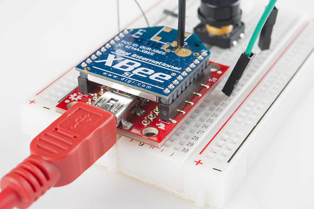
Each XBee pin is labelled on the bottom side of the board. You can also check out the schematic for help locating a specific pin.
If male headers don't fit your purpose, you can alternatively solder in female headers (to plug jumper wires into), or even just bare wire. Just make sure you don't solder anything into the top side of the board -- or you may be unable to plug the XBee in!
We won't cover it in this tutorial, but those "DIO#" pins can be configured as either inputs or outputs. That means you can use an XBee to directly drive LEDs or motors, and read analog sensors or buttons.