RedBot Assembly Guide Rev 02
This Tutorial is Retired!
This tutorial covers concepts or technologies that are no longer current. It's still here for you to read and enjoy, but may not be as useful as our newest tutorials.
 HelloTechie,
  SFUptownMaker
**RedBot Sensor - Mechanical Bumpers**
Read on if you are using the RedBot Sensor - Mechanical Bumpers. If not, skip to the next section.
You will need to prepare the music wire by bending the wire itself. Then, you will add standoffs and screws to your mechanical bumpers, followed by adding the mechanical bumpers to the RedBot chassis.
Locate the Following:
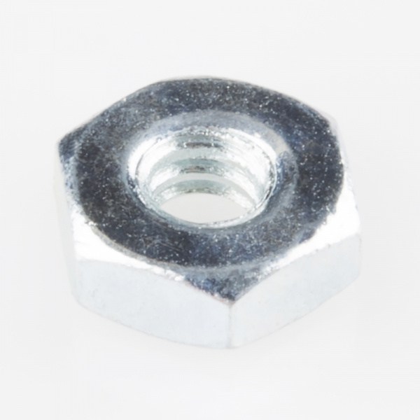
| 6x 4-40 x 3/8" Phillips screw | 2x 4-40 x 3/4" Nylon Standoff | 2x 4-40 Hex Nut |
 |
 |
 |
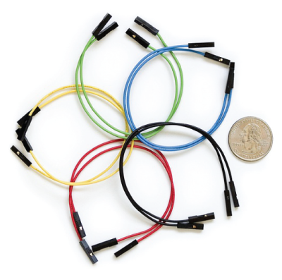
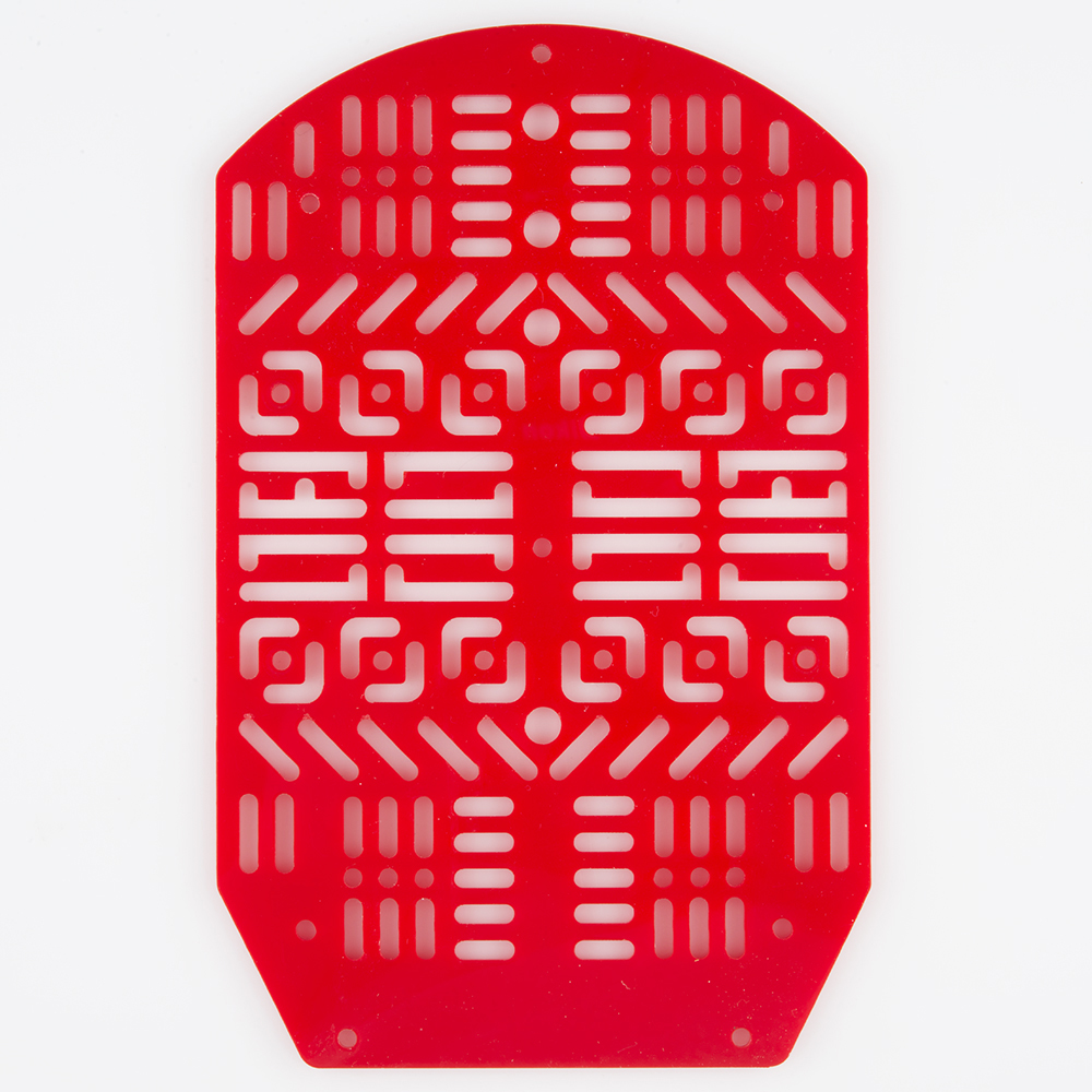
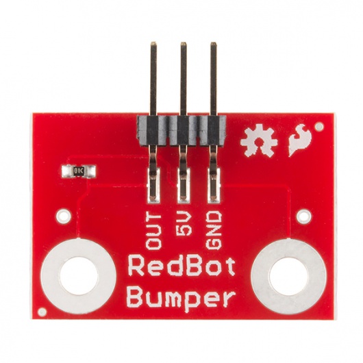
| 4x Jumper Wire | 1x RedBot Top Chassis | 2x RedBot Sensor - Mechanical Bumper |
 |
 |
 |
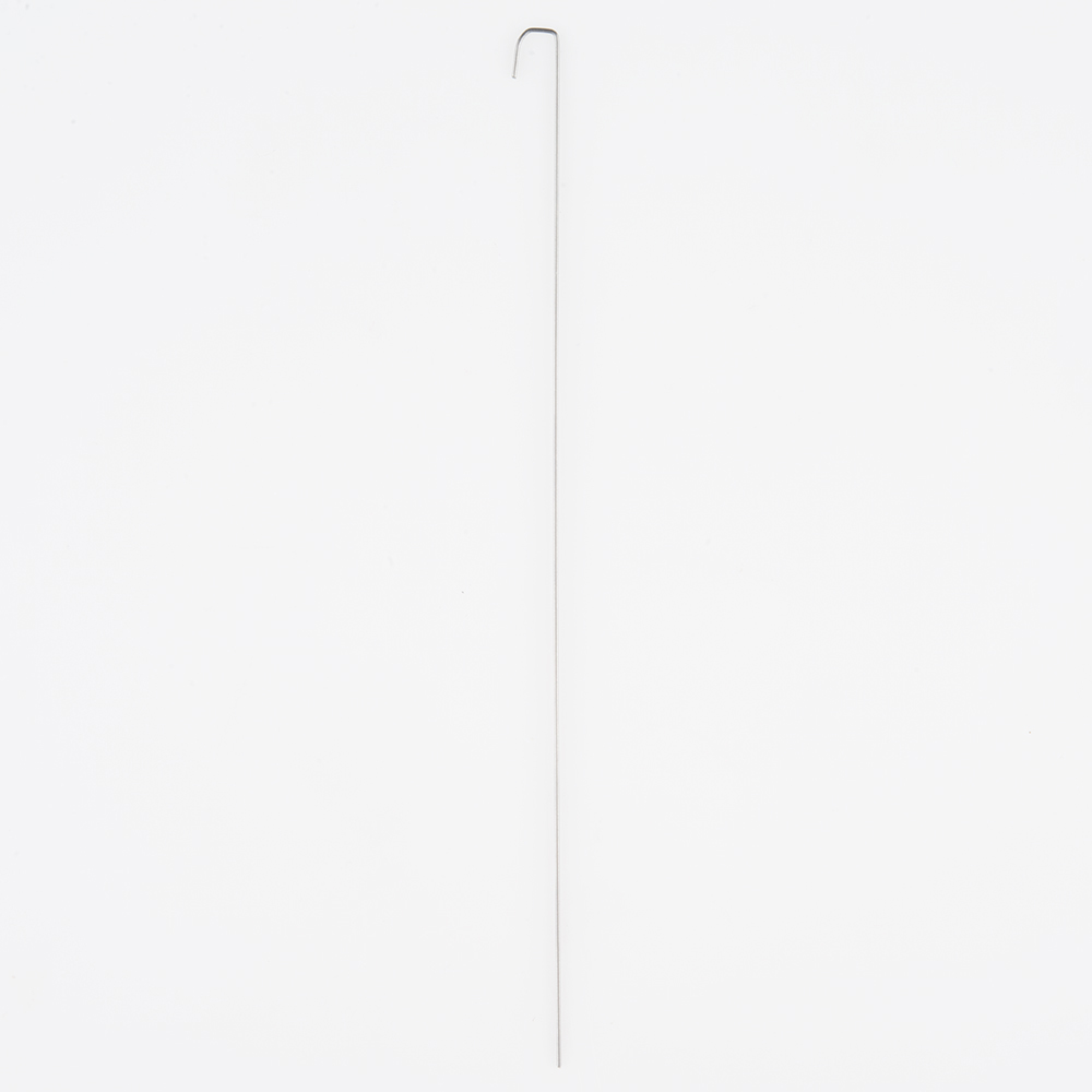
| 2x Whisker | ||
 |
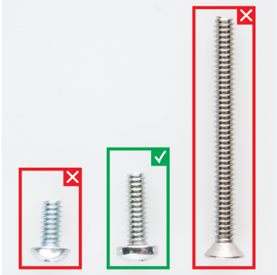
Please note: ** Pay close attention to which screws you are using. There are two different screws in the RedBot Kit. (30x** of the 4-40 x 1/4" Phillips screws and 4x of the 4-40 x 1 1/4" flat head screws).
Adding the RedBot Sensor - Mechanical Bumper? You will have 3x of the 4-40 x ⅜" Phillips screws.
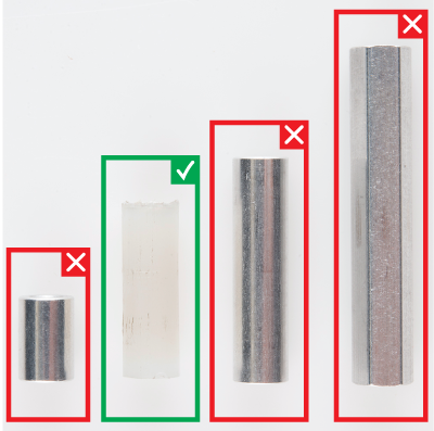
There are also different standoffs in the RedBot Kit and add-ons. The RedBot Kit comes with 7x 4-40 x 1" metal standoffs, 4x 4-40 x ⅜" metal standoffs, and 3x 4-40 x 1 1/2" metal hex standoffs.
Adding the RedBot Sensor - Mechanical Bumper? You will have 3x of the 4-40 x 3/4" nylon standoffs.
Prepare the RedBot Sensor - Mechanical Bumpers
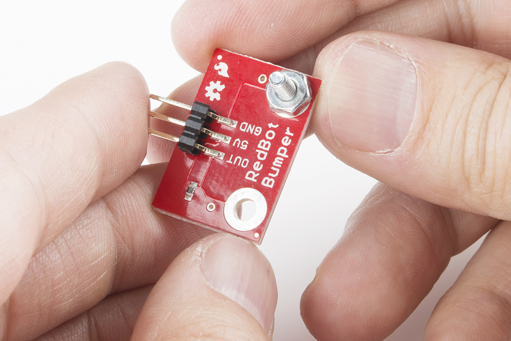
Screw a 4-40 x ⅜" Phillips screw and 4-40 hex nut to one of the two large mechanical bumper holes.
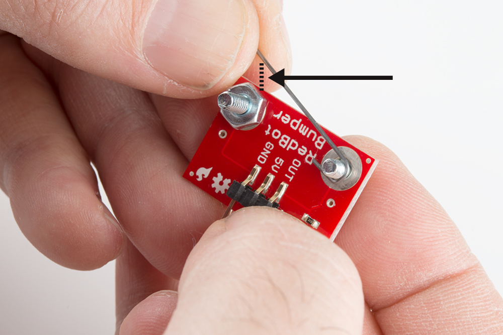
Time to bend the whisker! It is easy to bend the whisker with needle nose pliers. However, there is a trick to bend the whisker using the mechanical bumper PCB itself. First, stick one of the whiskers through one of the smaller side holes. It only needs to stick out a little bit.

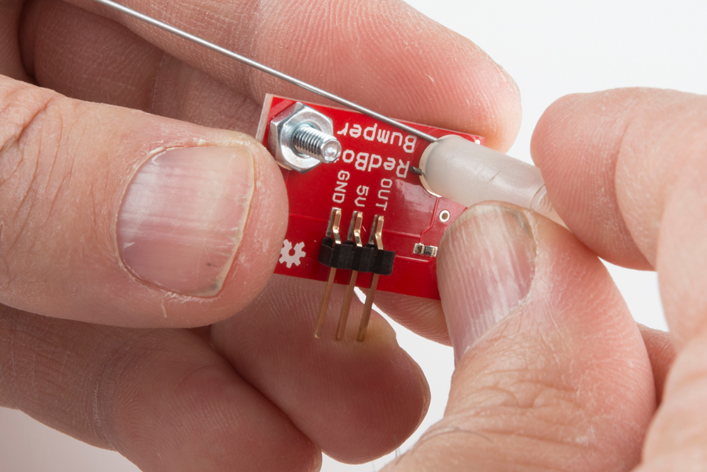
Bend the whisker 90 degrees.

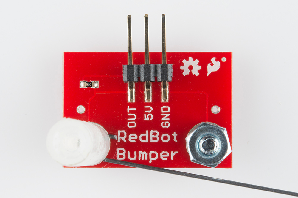
Bend the whisker 90 degrees again.

Now that the whisker is bent, take the wire out of the PCB hole. Add a 4-40 x ⅜" Phillips Screw from the bottom and loop the bent whisker around the screw. It is very important that you do not let the whisker touch the other side's 4-40 hex nut and 4-40 x ⅜" Phillips screw, since that is what triggers the sensor. Leave a little space between the wire and other side's nut.
Twist a 4-40 x 3/4" nylon standoff on top of the screw to secure the wire.
Double check that the wire does not touch the other side's 4-40 hex nut and 4-40 x ⅜" Phillips screw.
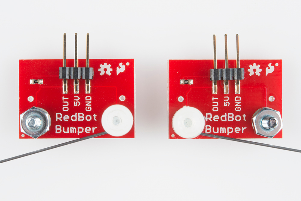
Do this for the other mechanical bumper. Take note of which side your 4-40 x 3/4" nylon standoff is on for the first mechanical bumper. Do the opposite for the other bumper. Double check that there is one mechanical bumper that has a 4-40 x 3/4" nylon standoff on the right side of the "RedBot Bumper" silkscreen and one that has a 4-40 x 3/4" nylon standoff on the left side.
Adding RedBot Sensor - Mechanical Bumpers
Locate the two positions on the top chassis piece.
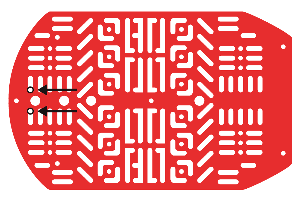
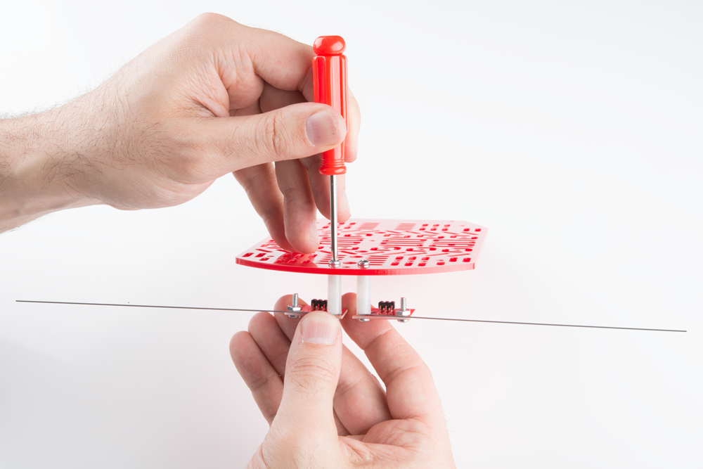
Using two 4-40 x 1/4" Phillips screws, tighten down the mechanical bumpers with the two wires pointing in opposite directions on the bottom side of the top chassis piece. The mechanical bumpers' header pins should be pointing toward the chassis piece.
Adding Jumper Wires to the RedBot Sensor - Mechanical Bumpers
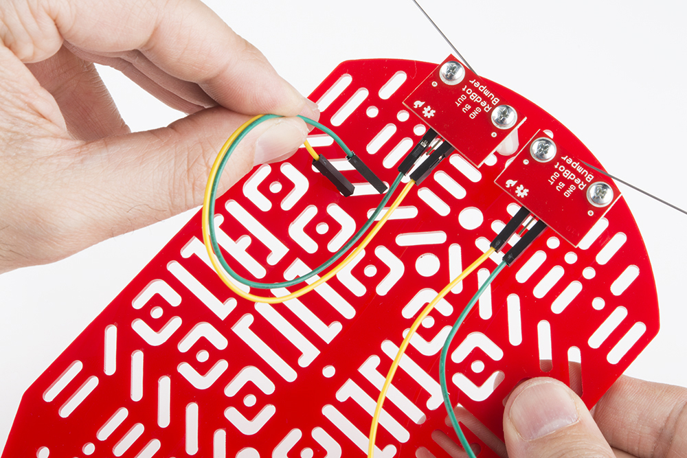
Add jumper wires to the GND and OUT pins on both of the mechanical bumpers. You will not add jumper wires to the 5V pins. Again, which color jumper wires you choose does not matter, but it might be helpful to follow along with this assembly guide.
Left RedBot Sensor - Mechanical Bumper:
| Jumper Wires | Left RedBot Sensor - Mechanical Bumper |
|---|---|
| Jumper Wire - Green | GND |
| Jumper Wire - Yellow | OUT |
Please note: When you have the RedBot upright and the front of the chassis facing north, the left mechanical bumper will be on the left side.
Right RedBot Sensor - Mechanical Bumper:
| Jumper Wires | Right RedBot Sensor - Mechanical Bumper |
|---|---|
| Jumper Wire - Yellow | GND |
| Jumper Wire - Green | OUT |
Please note: When you have the RedBot upright and the front of the chassis facing north, the right mechanical bumper will be on the right side.
Here is the view from the bottom side:

Put the other ends of the jumper wires through the top chassis piece.
Make sure the jumper wires are all the way through.
