Qwiic ToF Imager - VL53L5CX Hookup Guide
Contributors:
 Nate, Ell C
Nate, Ell C 
Example2_FastStartup
Hook up your ToF imager to your Artemis Thing Plus via the Qwiic cables, and click "File > Examples > SparkFun VL53L5CX Arduino Library > Example2_FastStartup".

We'll assume that you have selected the board (in this case the SparkFun Artemis Thing Plus) and the correct COM port at this point. If you have the code open, hit the upload button. Otherwise, copy and paste the following into the Arduino IDE, make sure to select the correct board and COM port, and then upload:
language:c
/*
  Read an 8x8 array of distances from the VL53L5CX
  By: Nathan Seidle
  SparkFun Electronics
  Date: October 26, 2021
  License: MIT. See license file for more information but you can
  basically do whatever you want with this code.

  This example shows how to setup the I2C bus to minimize the amount
  of time taken to init the sensor.

  At each power on reset, a staggering 86,000 bytes of firmware have to be sent to the sensor.
  At 100kHz, this can take ~9.4s. By increasing the clock speed, we can cut this time down to ~1.4s.

  Two parameters can be tweaked:

    Clock speed: The VL53L5CX has a max bus speed of 400kHz but we have had success up to 1MHz.

    Max transfer size: The majority of Arduino platforms default to 32 bytes. If you are using one
    with a larger buffer (ESP32 is 128 bytes for example), this can help decrease transfer times a bit.

  Measurements:
    Default 100kHz clock and 32 byte transfer: 9.4s
    400kHz, 32 byte transfer: 2.8s
    400kHz, 128 byte transfer: 2.5s
    1MHz, 32 byte transfer: 1.65s
    1MHz, 128 byte transfer: 1.4s

  Feel like supporting our work? Buy a board from SparkFun!
  https://www.sparkfun.com/products/18642

*/

#include <Wire.h>

#include <SparkFun_VL53L5CX_Library.h> //http://librarymanager/All#SparkFun_VL53L5CX

SparkFun_VL53L5CX myImager;
VL53L5CX_ResultsData measurementData; // Result data class structure, 1356 byes of RAM

int imageResolution = 0; //Used to pretty print output
int imageWidth = 0; //Used to pretty print output

void setup()
{
  Serial.begin(115200);
  delay(1000);
  Serial.println("SparkFun VL53L5CX Imager Example");

  Wire.begin(); //This resets I2C bus to 100kHz
  Wire.setClock(400000); //Sensor has max I2C freq of 400kHz
  //Wire.setClock(1000000); //Run sensor out of spec

  //myImager.setWireMaxPacketSize(128); //Increase default from 32 bytes to 128 - not supported on all platforms

  Serial.println("Initializing sensor board. This can take up to 10s. Please wait.");

  //Time how long it takes to transfer firmware to sensor
  long startTime = millis();
  bool startup = myImager.begin();
  long stopTime = millis();

  if (startup == false)
  {
    Serial.println(F("Sensor not found - check your wiring. Freezing"));
    while (1) ;
  }

  Serial.print("Firmware transfer time: ");
  float timeTaken = (stopTime - startTime) / 1000.0;
  Serial.print(timeTaken, 3);
  Serial.println("s");

  myImager.setResolution(8*8); //Enable all 64 pads

  imageResolution = myImager.getResolution(); //Query sensor for current resolution - either 4x4 or 8x8
  imageWidth = sqrt(imageResolution); //Calculate printing width

  myImager.startRanging();
}

void loop()
{
  //Poll sensor for new data
  if (myImager.isDataReady() == true)
  {
    if (myImager.getRangingData(&measurementData)) //Read distance data into array
    {
      //The ST library returns the data transposed from zone mapping shown in datasheet
      //Pretty-print data with increasing y, decreasing x to reflect reality
      for (int y = 0 ; y <= imageWidth * (imageWidth - 1) ; y += imageWidth)
      {
        for (int x = imageWidth - 1 ; x >= 0 ; x--)
        {
          Serial.print("\t");
          Serial.print(measurementData.distance_mm[x + y]);
        }
        Serial.println();
      }
      Serial.println();
    }
  }

  delay(5); //Small delay between polling
}
Open up your Serial Monitor, make sure the baud rate is set appropriately, and you should see something like the following:
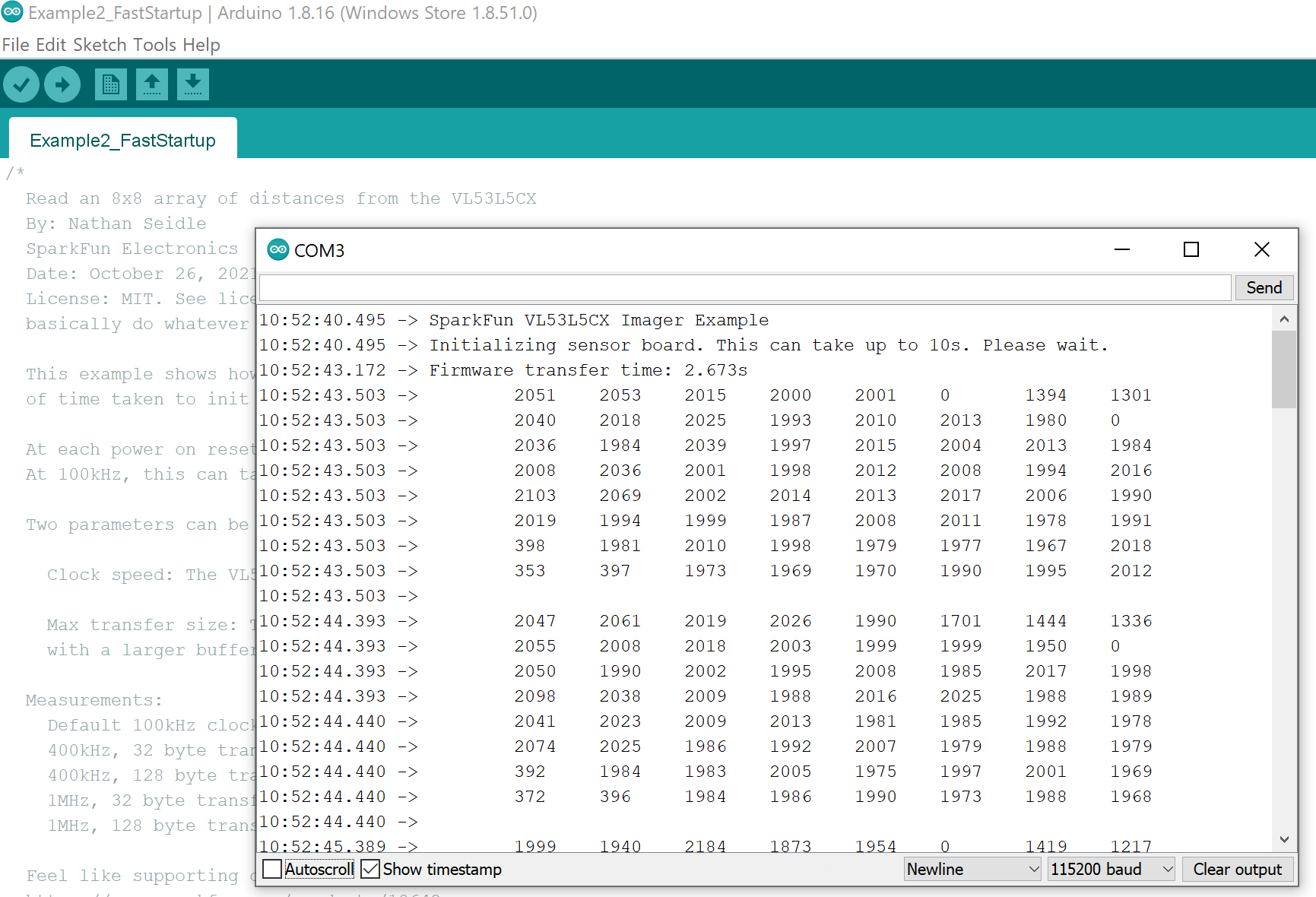
Click the image for a closer view