Qwiic Pro Micro USB-C (ATmega32U4) Hookup Guide
 bboyho
Hardware Overview
Before we get into installing and using the Qwiic Pro Micro, let's quickly look at the board -- examine its inputs, outputs, and other hardware quirks.
Old School to New School
The Qwiic Pro Micro USBC is a revision of the original Pro Micro. Overall, it is functionally the same as the previous version. The board is the same size as the original Pro Micro but we added a few additional features by shrinking down some components on the board. The major changes to the board that you will notice include:
- Reset Button
- USB C
- Castellated Pads
- Qwiic Connector
- AP2112 3.3V Voltage Regulator
The benefit of the reset button is to quickly reset the board or place it into bootloader mode without the need to take out a piece of jumper wire. The USB micro-b connector has been replaced with the USB type C connector. The through hole pads have castellated edges for each pin to add a lower profile in your projects should you decide build it into another assembly during production. Finally, a Qwiic connector is populated on the bottom of the board to easily add Qwiic enabled I2C devices.
 |
 |
| Older 5V/16MHz Pro Micro |
Newer 5V/16MHz Qwiic Pro Micro USB C |
A subtle difference that you may not notice is the old Pro Micro used the MIC5219, which was able to handle a maximum voltage input of 16VDC. The new Qwiic Pro Micro uses the AP2112 3.3V voltage regulator which can handle a maximum of 6V. The output current is slightly higher in the Qwiic Pro Micro which peaks at about 600mA. You'll need to make sure to use an appropriate voltage regulator and components and regulate the voltage down.
For more information about the differences between the boards, make sure to pull up the schematic for both boards and read further below!
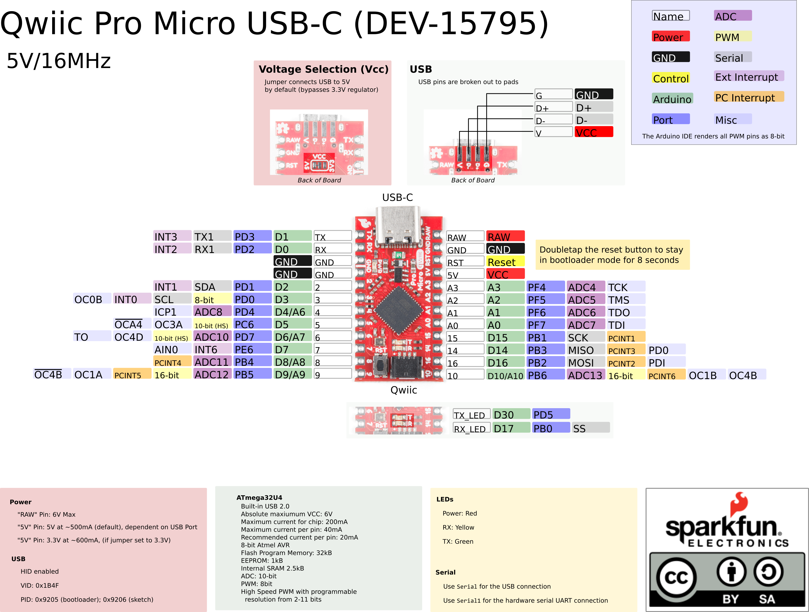
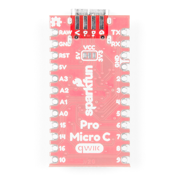
The Pinout
All of the Qwiic Pro Micro's I/O and power pins are broken out to two, parallel headers. Some pins are for power input or output, other pins are dedicated I/O pins. Further, the I/O pins can have special abilities, like analog input. Here's a map of which pin is where, and what special hardware functions it may have:
Power
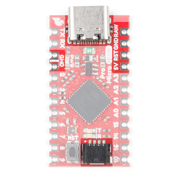
There are a variety of power and power-related nets broken out to connectors and through hole pads. Each pad has a castellated edge. The back of the board also has the USB pins broken out for power.
 |
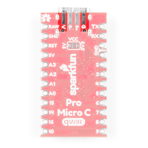 |
| Castellated Power and Reset Pins | USB Power Pins |
These nets consist of the following:
- V is the voltage provided from the USB connector.
- RAW is the unregulated voltage input for the Qwiic Pro Micro. If the board is powered via USB (i.e. V), the voltage at this pin will be about 4.8V (USB's 5V minus a Schottky diode drop). On the other hand, if the board is powered externally, through this pin, the applied voltage can be up to 6V.
- 5V is the voltage supplied to the on-board ATmega32U4. This voltage will depend on whether you have the jumper set to 5V (by default) or 3.3V.
- When the jumper is set to 5V, it is the voltage applied to the RAW pin. We suggest using a clean 5V power supply if you are connecting 5V devices to the I/O. If the board is powered through the 'RAW' pin (or USB), this pin can be used as an output to supply 5V for other devices.
- When the jumper is set to 3.3V, the output is 3.3V. If the board is powered through the 'RAW' pin (or USB), this pin can be used as an output to supply 3.3V for other devices.
- RST can be used to restart the Qwiic Pro Micro. There is a built-in reset button to reset the Pro Micro. However, the pin is broken out if you need to access this pin externally. This pin is pulled high by a 10kΩ resistor on the board, and is active-low, so it must be connected to ground to initiate a reset. The Qwiic Pro Micro will remain "off" until the reset line is pulled back to high.
- GND, of course, is the common, ground voltage (0V reference) for the system.
I/O Pins
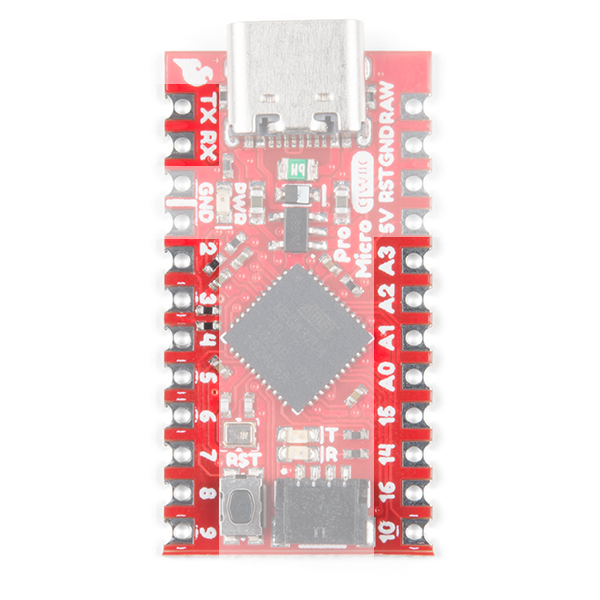
The Qwiic Pro Micro breaks out the I/O pins to plated through hole pads on the edge of the board. Each pad is castellated as well. On the back, there are additional pins to connect to the USB data pins.
 |
 |
| Castellated I/O PTH Pads | USB Pads |
The Pro Micro's I/O pins -- 18 in all -- are multi-talented. Every pin can be used as a digital input or output, for blinking LEDs or reading button presses. These pins are referenced in the Arduino IDE via an integer value between 0 and 21. (The A0-A3 pins can be referenced digitally using either their analog or digital pin number).
Nine pins feature analog to digital converters (ADCs) and can be used as analog inputs. These are useful for reading potentiometers or other analog devices using the analogRead([pin]) function.
There are five pins with pulse width modulation (PWM) functionality, which allows for a form of analog output using the analogWrite([pin], [value]) function. These pins are indicated on-board with a faint, white circle around the square pads.
There are hardware UART (serial), I2C, and SPI pins available as well. These can be used to interface with digital devices like serial LCDs, XBees, IMUs, and other serial sensors.
The Pro Micro has five external interrupts, which allow you to instantly trigger a function when a pin goes either high or low (or both). If you attach an interrupt to an interrupt-enabled pin, you'll need to know the specific interrupt that pin triggers: pin 3 maps to interrupt 0 (INT0), pin 2 is interrupt 1 (INT1), pin 0 is interrupt 2 (INT2), pin 1 is interrupt 3 (INT3), and pin 7 is interrupt 4 (INT6).
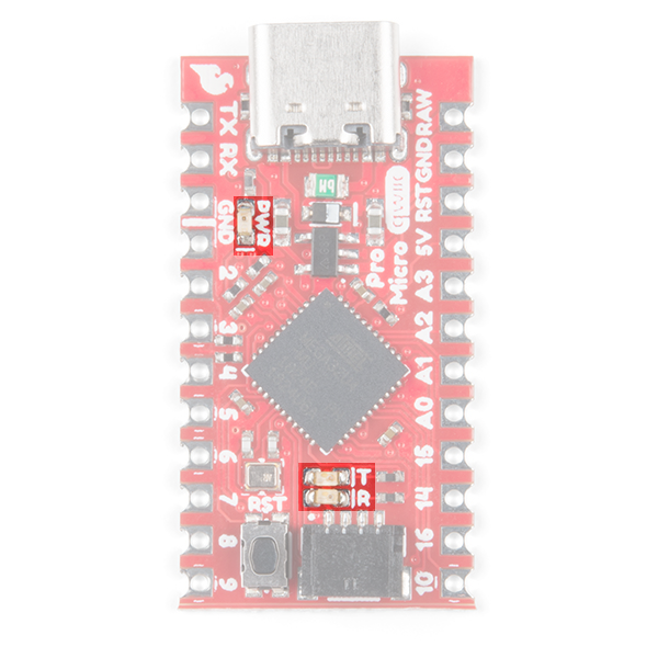
On-Board LEDs
There are three LEDs on the Pro Micro. One red LED indicates whether power is present. The other two LEDs help indicate when data is transferring over USB. A yellow LED represents USB data coming into (RX) the Pro Micro, and a green LED indicates USB data going out (TX).
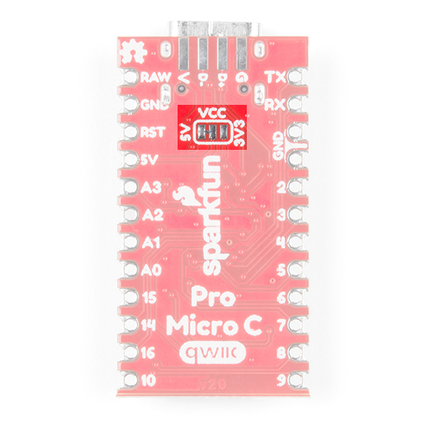
Jumpers
On the back of the board is a jumper that is able to select the system voltage. The default voltage for the board defaults to 5V. By cutting the jumper pad and adding a solder to the between the center and right jumper pads, the system voltage will be set to 3.3V.
Board Dimensions
The board measures 1.30" x 0.70". Not included in the image below is the PCB thickness, which is 0.8mm. This is thinner than a majority of the PCBs used for SparkFun original designs.

How to Power the Qwiic Pro Micro USB C
As the Pro Micro's main feature is its innate USB functionality, the most common way to power it is via USB. If the jumper is set to the default 5V, the Qwiic Pro Micro will be powered directly from the USB bus. If the jumper is set to 3.3V, the board will regulate the 5V supply coming in from USB down to 3.3V. The other end of the USB cable can be connected to either a computer, USB hub, USB batteries, or a USB wall adapter, which can (in most cases) provide more power.
Alternatively, if your Qwiic Pro Micro is living out in the wild, out of reach of USB cables, it can be powered through either the 'RAW' or '5V' pins. A supply going into those pins will provide power to the Qwiic Pro Micro. To be safe, it shouldn't be any higher than 6V. If the jumper is set to 3.3V, the voltage will be regulated down to 3.3V.
How, exactly, you power your project is up to you and the demands of your project. If you're making something battery powered, you could use a LiPo boost converter to power the board at 5V. Or you may want to set the jumper to 3.3V, which could be powered by a LiPo battery or a couple alkalines. Make sure to check out the following tutorials for more information.