$29.95
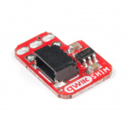
The VL53L1X is the latest Time Of Flight (ToF) sensor to be released. It uses a VCSEL (vertical cavity surface emitting laser) to emit a class 1 IR laser (940 nm) and time the reflection to the target. (You can’t see the laser but cell phones can) What does all this mean? You can measure the distance to an object up to 4 meters away with millimeter resolution! That’s pretty incredible.
We’ve found the precision of the sensor to be 1mm but the accuracy is around +/-5mm. The minimum read distance of this sensor is 4cm. In this hookup guide we'll go over how to read distance, change ranging modes, and check the status of our range measurement along with the sample rate. We'll also check out how to display distance and speed over an LCD display.
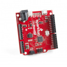
The Qwiic Distance Sensor does need a few additional items for you to get started. The RedBoard Qwiic is for the Arduino examples and the Qwiic pHAT is for the Raspberry Pi example (see note below). You may already have a few of these items, so feel free to modify your cart based on your needs. Additionally, there are also alternative parts options that are available as well (click button below to toggle options).


If you're unfamiliar with jumper pads, I2C, Qwiic, or Python be sure to checkout some of these foundational tutorials.
The Qwiic Distance Sensor is intended for the Qwiic connect system. We recommend familiarizing yourself with the Logic Levels and I2C tutorials before using it. Click on the banner above to learn more about our Qwiic products.
First let's check out some of the characteristics of the VL53L1X sensor we're dealing with, so we know what to expect out of the board.
| Characteristic | Range |
|---|---|
| Operating Voltage | 2.6V-3.5V |
| Power Consumption | 20 mW @10Hz |
| Measurement Range | ~40mm to 4,000mm |
| Resolution | +/-1mm |
| Light Source | Class 1 940nm VCSEL |
| I2C Address | 0x29 |
| Field of View | 15° - 27° |
| Max Read Rate | 50Hz |
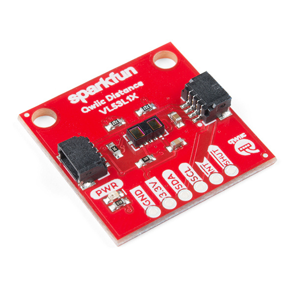
The following table lists all of the VL53L1X's pins and their functionality.
| Pin | Description | Direction |
|---|---|---|
| GND | Ground | In |
| 3.3V | Power | In |
| SDA | Data | In |
| SCL | Clock | In |
| INT | Interrupt, goes low when data is ready. | Out |
| SHUT | Shutdown, can be pulled low to put the IC in shutdown mode. | In |
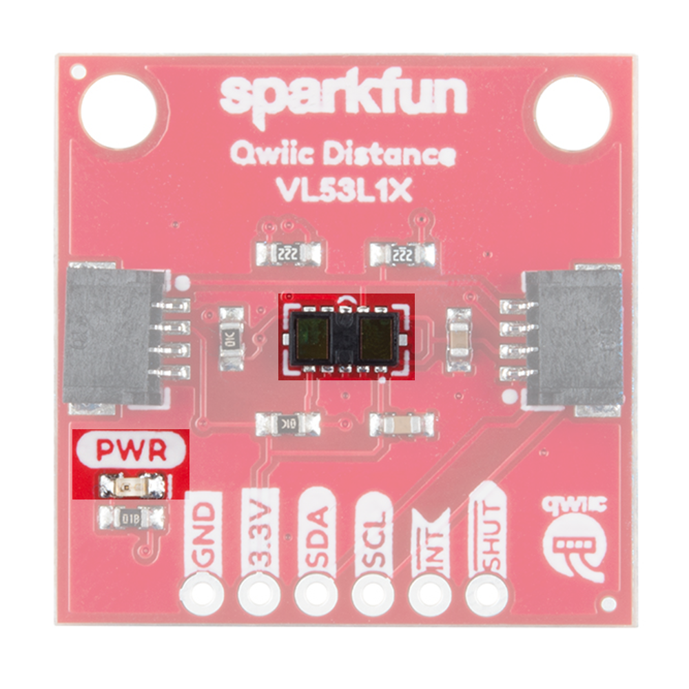
The VL53L1X breakout has pull up resistors attached to the I2C bus as well as the interrupt pin; if multiple sensors are connected to the bus with the pull-up resistors enabled, the parallel equivalent resistance will create too strong of a pull-up for the bus to operate correctly. As a general rule of thumb, disable all but one pair of pull-up resistors if multiple devices are connected to the bus. If you need to disconnect the pull up resistors they can be removed by cutting the traces on the corresponding jumpers highlighted below.

The onboard LED (highlighted below) will light up when the board is powered, and the sensor (also highlighted below) should be left uncovered in your application.
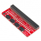
If you haven't yet assembled your Qwiic Shield, now would be the time to head on over to that tutorial. Depending on the microcontroller and shield you've chosen, your assembly may be different, but here's a handy link to the Qwiic Shield for Arduino and Photon Hookup Guide to get you started!
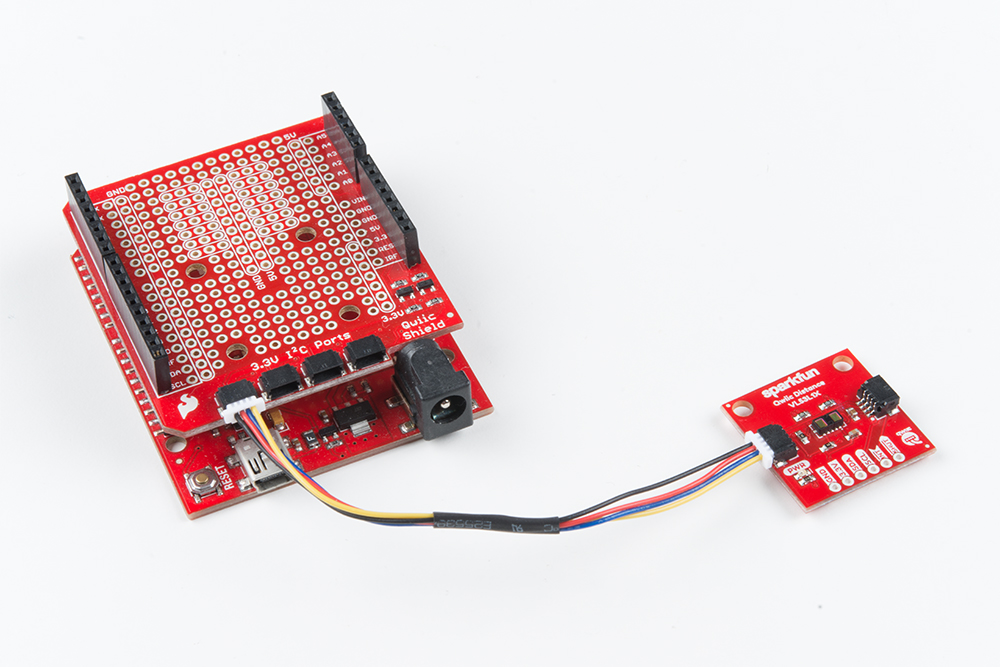
With the shield assembled, SparkFun's new Qwiic environment means that connecting the sensor could not be easier. Just plug one end of the Qwiic cable into the VL53L1X breakout, the other into the Qwiic Shield and you'll be ready to upload a sketch and figure out how far away you are from that thing over there. It seems like it's too easy too use, but that's why we made it that way!
Note: This example assumes you are using the latest version of the Arduino IDE on your desktop. If this is your first time using Arduino, please review our tutorial on installing the Arduino IDE. If you have not previously installed an Arduino library, please check out our installation guide.
First, you'll need the SparkFun VL53L1X Arduino library, which is an easy to use wrapper of ST's driver. You can obtain these libraries through the Arduino Library Manager. Search for Sparkfun VL53L1X Arduino Library to install the latest version. If you prefer downloading the libraries from the GitHub repository and manually installing it, you can grab them here:
Before we get started developing a sketch, let's look at the available functions of the library.
boolean init(); --- Initialize the sensorvoid startRanging(); --- Starts taking measurements.void stopRanging(); --- Stops taking measurements.bool checkForDataReady(); --- Checks if a measurement is ready.void setTimingBudgetInMs(uint16_t timingBudget) --- Set the timing budget for a measurement in ms. The timing budget is the amount of time over which a measurement is taken. This can be set to any of the following.
uint16_t getTimingBudgetInMs(); --- Get's the current timing budget in ms.void setDistanceModeLong(); --- Sets to 4M range.void setDistanceModeShort(); --- Sets to 1.3M rangeuint8_t getDistanceMode(); --- Returns 1 for short range, 2 for long range.void setIntermeasurementPeriod(uint16_t intermeasurement); --- Set's the period in between measurements. Must be greater than or equal to the timing budget. Default is 100 ms.uint16_t getIntermeasurementPeriod(); --- Returns the intermeasurement period in ms.bool checkBootState(); --- Checks whether the device has been booted. Returns true if the device has been booted.uint16_t getSensorID(); --- Get the sensor ID, should be 0xEEAC.uint16_t getDistance(); --- Returns the results from the last measurement, distance in mmuint16_t getSignalPerSpad(); --- Returns the average signal rate per SPAD (The sensitive pads that detect light, the VL53L1X has a 16x16 array of these) in kcps/SPAD, or kilo counts per second per SPAD.uint16_t getAmbientPerSpad(); --- Returns the ambient noise when not measuring a signal in kcps/SPAD.uint16_t getSignalRate(); --- Returns the signal rate in kcps. All SPADs combined.uint16_t getSpadNb(); --- Returns the current number of enabled SPADsuint16_t getAmbientRate(); --- Returns the total ambinet rate in kcps. All SPADs combined.uint8_t getRangeStatus(); --- Returns the range status, which can be any of the following.
void setOffset(int16_t offset); --- Manually set an offset for a measurement in mm.int16_t getOffset(); --- Get the current offset in mm.void setXTalk(uint16_t xTalk); --- Manually set the value of crosstalk in counts per second (cps), which is interference from any sort of window in front of your sensor.uint16_t getXTalk(); --- Returns the current crosstalk value in cps.void setDistanceThreshold(uint16_t lowThresh, uint16_t hiThresh, uint8_t window); --- Set bounds for the interrupt. lowThresh and hiThresh are the bounds of your interrupt while window decides when the interrupt should fire. The options for window are shown below.
uint16_t getDistanceThresholdWindow(); --- Returns distance threshold window option.uint16_t getDistanceThresholdLow(); --- Returns lower bound in mm.uint16_t getDistanceThresholdHigh(); --- Returns upper bound in mmvoid setROI(uint16_t x, uint16_t y, uint8_t opticalCenter); --- Set the height and width of the ROI in SPADs, lowest possible option is 4. The center of the ROI you set is based on the table below. Set the opticalCenter as the pad above and to the right of your exact center.| 128 | 136 | 144 | 152 | 160 | 168 | 176 | 184 | 192 | 200 | 208 | 216 | 224 | 232 | 240 | 248 |
| 129 | 137 | 145 | 153 | 161 | 169 | 177 | 185 | 193 | 201 | 209 | 217 | 225 | 233 | 241 | 249 |
| 130 | 138 | 146 | 154 | 162 | 170 | 178 | 186 | 194 | 202 | 210 | 218 | 226 | 234 | 242 | 250 |
| 131 | 139 | 147 | 155 | 163 | 171 | 179 | 187 | 195 | 203 | 211 | 219 | 227 | 235 | 243 | 251 |
| 132 | 140 | 148 | 156 | 164 | 172 | 180 | 188 | 196 | 204 | 212 | 220 | 228 | 236 | 244 | 252 |
| 133 | 141 | 149 | 157 | 165 | 173 | 181 | 189 | 197 | 205 | 213 | 221 | 229 | 237 | 245 | 253 |
| 134 | 142 | 150 | 158 | 166 | 174 | 182 | 190 | 198 | 206 | 214 | 222 | 230 | 238 | 246 | 254 |
| 135 | 143 | 151 | 159 | 167 | 175 | 183 | 191 | 199 | 207 | 215 | 223 | 231 | 239 | 247 | 255 |
| 127 | 119 | 111 | 103 | 95 | 87 | 79 | 71 | 63 | 55 | 47 | 39 | 31 | 23 | 15 | 7 |
| 126 | 118 | 110 | 102 | 94 | 86 | 78 | 70 | 62 | 54 | 46 | 38 | 30 | 22 | 14 | 6 |
| 125 | 117 | 109 | 101 | 93 | 85 | 77 | 69 | 61 | 53 | 45 | 37 | 29 | 21 | 13 | 5 |
| 124 | 116 | 108 | 100 | 92 | 84 | 76 | 68 | 60 | 52 | 44 | 36 | 28 | 20 | 12 | 4 |
| 123 | 115 | 107 | 99 | 91 | 83 | 75 | 67 | 59 | 51 | 43 | 35 | 27 | 19 | 11 | 3 |
| 122 | 114 | 106 | 98 | 90 | 82 | 74 | 66 | 58 | 50 | 42 | 34 | 26 | 18 | 10 | 2 |
| 121 | 113 | 105 | 97 | 89 | 81 | 73 | 65 | 57 | 49 | 41 | 33 | 25 | 17 | 9 | 1 |
| 120 | 112 | 104 | 96 | 88 | 80 | 72 | 64 | 56 | 48 | 40 | 32 | 24 | 16 | 8 | 0 |
uint16_t getROIX(); --- Returns the width of the ROI in SPADsuint16_t getROIY(); --- Returns the height of the ROI in SPADsvoid setSignalThreshold(uint16_t signalThreshold); --- Programs the necessary threshold to trigger a measurement. Default is 1024 kcps.uint16_t getSignalThreshold(); --- Returns the signal threshold in kcpsvoid setSigmaThreshold(uint16_t sigmaThreshold); --- Programs a new sigma threshold in mm. (default=15 mm)uint16_t getSigmaThreshold(); --- Returns the current sigma threshold.void startTemperatureUpdate(); --- Recalibrates the sensor for temperature changes. Run this any time the temperature has changed by more than 8°Cvoid calibrateOffset(uint16_t targetDistanceInMm); --- Autocalibrate the offset by placing a target a known distance away from the sensor and passing this known distance into the function.void calibrateXTalk(uint16_t targetDistanceInMm); --- Autocalibrate the crosstalk by placing a target a known distance away from the sensor and passing this known distance into the function.Now that we have our library installed and we understand the basic functions, let's run some examples for our distance sensor to see how it behaves.
To get started with the first example, open up File > Examples > SparkFun VL53L1x 4M Laser Distance Sensor > Example1_ReadDistance. In this example, we begin by creating a SFEVL53L1X object called distanceSensor with our wire port, Wire, and then our shutdown and interrupt pins. Then we initialize our sensor object in the setup() loop. The code to do this is shown below and is repeated in some form in all of the examples.
language:c
#include <Wire.h>
#include "SparkFun_VL53L1X.h"

//Optional interrupt and shutdown pins.
#define SHUTDOWN_PIN 2
#define INTERRUPT_PIN 3

SFEVL53L1X distanceSensor(Wire, SHUTDOWN_PIN, INTERRUPT_PIN);

void setup(void)
{
  Wire.begin();

  Serial.begin(9600);
  Serial.println("VL53L1X Qwiic Test");

  if (distanceSensor.init() == false)
    Serial.println("Sensor online!");

}
Once we've initialized our sensor, we can start grabbing measurements from it. To do this, we send some configuration bytes to our sensor using distanceSensor.startRanging() to initiate the measurement. We then wait for data to become available and when it does, we read it in, convert it from millimeters to feet, and print it out over serial. The void loop() function that does this is shown below.
language:c
void loop(void)
{
  distanceSensor.startRanging(); //Write configuration bytes to initiate measurement
  int distance = distanceSensor.getDistance(); //Get the result of the measurement from the sensor
  distanceSensor.stopRanging();

  Serial.print("Distance(mm): ");
  Serial.print(distance);

  float distanceInches = distance * 0.0393701;
  float distanceFeet = distanceInches / 12.0;

  Serial.print("\tDistance(ft): ");
  Serial.print(distanceFeet, 2);

  Serial.println();
}
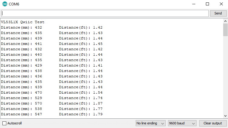
Opening your serial monitor to a baud rate of 9600 should show the distance between the sensor and the object it's pointed at in both millimeters and feet. The output should look something like the below image.
In this example, we'll change the distance mode of the VL53L1X. The default long range mode is the most robust as far as sample rate and range are concerned, but for a slightly higher sample rate, you can bring the range down to short (~1.3M). To get started with the second example, open up File > Examples > SparkFun VL53L1x 4M Laser Distance Sensor > Example2_SetDistanceMode. The main difference between this example and the previous example is that we call distanceSensor.setDistanceModeShort to change the range of our sensor to short range. Although this feature is available, we'd recommend sticking with long range as it is the most robust.
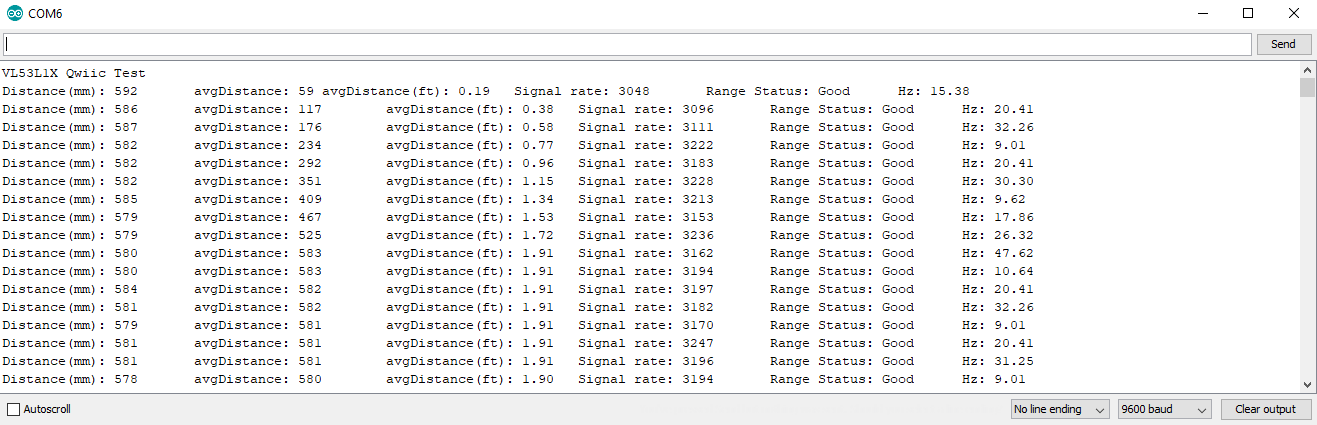
In the third example, we'll read and average our distance as well as read the sample rate and status of each measurement. To get started with the third example, open up File > Examples > SparkFun VL53L1x 4M Laser Distance Sensor > ExampleStatusandRate. The status of a measurement can be any of 8 values. Our void loop() interprets the value returned by distanceSensor.getRangeStatus() and prints that value over serial. The below table shows the possible values of rangeStatus and their corresponding errors.
| Range Status | Error |
|---|---|
| 0 | Valid measurement |
| 1 | Raised if sigma estimator (uncertainty in measurement) check is above the internal defined threshold |
| 2 | Raised if signal value is below the internal defined threshold |
| 4 | Raised when phase is out of bounds |
| 5 | Raised in case of HW or VCSEL failure |
| 7 | Wrapped target, not matching phases |
| 8 | Internal algorithm underflow or overflow |
| 14 | The reported range is invalid |
In the example code, notice how the sketch stores our previous values in the array history so that the average distance can also be calculated. Uploading this sketch to your microcontroller and opening the serial monitor to a baud rate of 9600 should give you an output similar to the image shown below.
The fourth example allows you to change the time alotted for a measurement. The VL53L1X will send out a laser pulse and then listen for the alotted time. We'd recommend 20, 33, and 100 ms for short, medium and long distance modes respectively. To open up the example, head to File > Examples > SparkFun VL53L1x 4M Laser Distance Sensor > Example4_SetIntermeasurementPeriod. There's not much that needs to be done to change the intermeasurement period other than a call to distanceSensor.setIntermeasurementPeriod(33) to change the time alotted time for a measurement to 33 ms. This will give us a data rate of roughly 30 Hz, lengthening the intermeasurement period will give us a lower sample rate, but will yield higher accuracy at longer ranges. Opening the serial monitor should yield an output similar to example 1.
The fifth example requires a serial enabled LCD screen for us to write our distance values to. If you haven't played around with a Serial enabled LCD before, checkout our hookup guide on the matter. To get started with the fourth example, open up File > Examples > SparkFun VL53L1x 4M Laser Distance Sensor > Example5_LCDDemo. We'll first need to connect the RX pin of our Serial LCD to pin A3 on our Arduino. Connect 5V and ground on the LCD and the backlight should light up. Notice how we also include the SoftwareSerial library. Uploading the sketch to our Arduino then takes in our sample rate and distances. By using these values, it calculates a velocity. Like the sketch before, distances are stored in an array. The sketch uses these values in the array to calculate velocity and the velocity is then displayed along with the current distance on the LCD. The output on the LCD should look something like the below GIF.
Note: This sensor and the Python package have not been tested on the newly released Raspberry Pi 4.
Update: This package has been updated to version 1.0.1 (released 1-20-2020), which is not backwards compatible with the previous packages. The package still retains the same functionality as version 0.9.4; however, most of the methods have been renamed to conform to the more "Pythonic" naming conventions (i.e. not camel case). For more details, check out the commit history in the GitHub repository.
Note: This example assumes you are using the latest version of Python 3. If this is your first time using Python or I2C hardware on a Raspberry Pi, please checkout our tutorial on Python Programming with the Raspberry Pi and the Raspberry Pi SPI and I2C Tutorial.
We've written a Python package to easily get setup and take readings from the Qwiic Distance Sensor. However, before we jump into getting data from the sensor, let's take a closer look at the available functions in the Python package. You can install the sparkfun-qwiic-vl53l1x Python package hosted by PyPi. However, if you prefer to manually download and build the libraries from the GitHub repository, you can grab them here (*Please be aware of any package dependencies. You can also check out the repository documentation page, hosted on Read the Docs.):
Note: Don't forget to double check that the hardware I2C connection is enabled on your Raspberry Pi or other single board computer.
This repository is hosted on PyPi as the sparkfun-qwiic-vl53l1x package. On systems that support PyPi installation via pip3 (use pip for Python 2) is simple, using the following commands:
For all users (note: the user must have sudo privileges):
language:bash
sudo pip3 install sparkfun-qwiic-vl53l1x
For the current user:
language:bash
pip3 install sparkfun-qwiic-vl53l1x
To install, make sure the setuptools package is installed on the system.
Direct installation at the command line (use python for Python 2):
language:bash
python3 setup.py install
To build a package for use with pip3:
language:bash
python3 setup.py sdist
A package file is built and placed in a subdirectory called dist. This package file can be installed using pip3.
language:bash
cd dist
pip3 install sparkfun_qwiic_vl53l1x-<version>.tar.gz
Below is a description of the basic functionality of the Python package. This includes the package organization, built-in methods, and their inputs and/or outputs. For more details on how the Python package works, check out the source code, sensor datasheet, and API user manual.
This Python package has a very few dependencies in the code, listed below:
language:python
import time                         # Time access and conversion package
import math                         # Basic math package
import qwiic_i2c                    # I2C bus driver package
The default variables, in the code, for this Python package are listed below:
language:python
# From vL53l1x_class.h Header File
###############################################################################
###############################################################################
SOFT_RESET =                                                            0x0000
VL53L1_I2C_SLAVE__DEVICE_ADDRESS =                                      0x0001
VL53L1_VHV_CONFIG__TIMEOUT_MACROP_LOOP_BOUND =                          0x0008
ALGO__CROSSTALK_COMPENSATION_PLANE_OFFSET_KCPS =                        0x0016
ALGO__CROSSTALK_COMPENSATION_X_PLANE_GRADIENT_KCPS =                    0x0018
ALGO__CROSSTALK_COMPENSATION_Y_PLANE_GRADIENT_KCPS =                    0x001A
ALGO__PART_TO_PART_RANGE_OFFSET_MM =                                    0x001E
MM_CONFIG__INNER_OFFSET_MM =                                            0x0020
MM_CONFIG__OUTER_OFFSET_MM =                                            0x0022
GPIO_HV_MUX__CTRL =                                                     0x0030
GPIO__TIO_HV_STATUS =                                                   0x0031
SYSTEM__INTERRUPT_CONFIG_GPIO =                                         0x0046
PHASECAL_CONFIG__TIMEOUT_MACROP =                                       0x004B
RANGE_CONFIG__TIMEOUT_MACROP_A_HI =                                     0x005E
RANGE_CONFIG__VCSEL_PERIOD_A =                                          0x0060
RANGE_CONFIG__VCSEL_PERIOD_B =                                          0x0063
RANGE_CONFIG__TIMEOUT_MACROP_B_HI =                                     0x0061
RANGE_CONFIG__TIMEOUT_MACROP_B_LO =                                     0x0062
RANGE_CONFIG__SIGMA_THRESH =                                            0x0064
RANGE_CONFIG__MIN_COUNT_RATE_RTN_LIMIT_MCPS =                           0x0066
RANGE_CONFIG__VALID_PHASE_HIGH =                                        0x0069
VL53L1_SYSTEM__INTERMEASUREMENT_PERIOD =                                0x006C
SYSTEM__THRESH_HIGH =                                                   0x0072
SYSTEM__THRESH_LOW =                                                    0x0074
SD_CONFIG__WOI_SD0 =                                                    0x0078
SD_CONFIG__INITIAL_PHASE_SD0 =                                          0x007A
ROI_CONFIG__USER_ROI_CENTRE_SPAD =                                      0x007F
ROI_CONFIG__USER_ROI_REQUESTED_GLOBAL_XY_SIZE =                         0x0080
SYSTEM__SEQUENCE_CONFIG =                                               0x0081
VL53L1_SYSTEM__GROUPED_PARAMETER_HOLD =                                 0x0082
SYSTEM__INTERRUPT_CLEAR =                                               0x0086
SYSTEM__MODE_START =                                                    0x0087
VL53L1_RESULT__RANGE_STATUS =                                           0x0089
VL53L1_RESULT__DSS_ACTUAL_EFFECTIVE_SPADS_SD0 =                         0x008C
RESULT__AMBIENT_COUNT_RATE_MCPS_SD =                                    0x0090
VL53L1_RESULT__FINAL_CROSSTALK_CORRECTED_RANGE_MM_SD0 =                 0x0096
VL53L1_RESULT__PEAK_SIGNAL_COUNT_RATE_CROSSTALK_CORRECTED_MCPS_SD0 =    0x0098
VL53L1_RESULT__OSC_CALIBRATE_VAL =                                      0x00DE
VL53L1_FIRMWARE__SYSTEM_STATUS =                                        0x00E5
VL53L1_IDENTIFICATION__MODEL_ID =                                       0x010F
VL53L1_ROI_CONFIG__MODE_ROI_CENTRE_SPAD =                               0x013E

_VL53L1X_DEFAULT_DEVICE_ADDRESS =                                       0x52
###############################################################################
###############################################################################

_DEFAULT_NAME = "Qwiic 4m Distance Sensor (ToF)"

###############################################################################
###############################################################################
_FULL_ADDRESS_LIST = list(range(0x08,0x77+1))                   # Full I2C Address List (excluding resrved addresses)
_FULL_ADDRESS_LIST.remove(_VL53L1X_DEFAULT_DEVICE_ADDRESS >> 1) # Remove Default Address of VL53L1X from list
_AVAILABLE_I2C_ADDRESS = [_VL53L1X_DEFAULT_DEVICE_ADDRESS >> 1] # Initialize with Default Address of VL53L1X
_AVAILABLE_I2C_ADDRESS.extend(_FULL_ADDRESS_LIST)               # Add Full Range of I2C Addresses


# From vL53l1x_class.cpp C++ File
###############################################################################
###############################################################################
ALGO__PART_TO_PART_RANGE_OFFSET_MM =                                    0x001E
MM_CONFIG__INNER_OFFSET_MM =                                            0x0020
MM_CONFIG__OUTER_OFFSET_MM =                                            0x0022

# DEBUG_MODE

VL51L1X_DEFAULT_CONFIGURATION = [
0x00,   # 0x2d : set bit 2 and 5 to 1 for fast plus mode (1MHz I2C), else don't touch
0x01,   # 0x2e : bit 0 if I2C pulled up at 1.8V, else set bit 0 to 1 (pull up at AVDD)
0x01,   # 0x2f : bit 0 if GPIO pulled up at 1.8V, else set bit 0 to 1 (pull up at AVDD)
0x01,   # 0x30 : set bit 4 to 0 for active high interrupt and 1 for active low (bits 3:0 must be 0x1), use SetInterruptPolarity()
0x02,   # 0x31 : bit 1 = interrupt depending on the polarity, use CheckForDataReady()
0x00,   # 0x32 : not user-modifiable
0x02,   # 0x33 : not user-modifiable
0x08,   # 0x34 : not user-modifiable
0x00,   # 0x35 : not user-modifiable
0x08,   # 0x36 : not user-modifiable
0x10,   # 0x37 : not user-modifiable
0x01,   # 0x38 : not user-modifiable
0x01,   # 0x39 : not user-modifiable
0x00,   # 0x3a : not user-modifiable
0x00,   # 0x3b : not user-modifiable
0x00,   # 0x3c : not user-modifiable
0x00,   # 0x3d : not user-modifiable
0xff,   # 0x3e : not user-modifiable
0x00,   # 0x3f : not user-modifiable
0x0F,   # 0x40 : not user-modifiable
0x00,   # 0x41 : not user-modifiable
0x00,   # 0x42 : not user-modifiable
0x00,   # 0x43 : not user-modifiable
0x00,   # 0x44 : not user-modifiable
0x00,   # 0x45 : not user-modifiable
0x20,   # 0x46 : interrupt configuration 0->level low detection, 1-> level high, 2-> Out of window, 3->In window, 0x20-> New sample ready , TBC
0x0b,   # 0x47 : not user-modifiable
0x00,   # 0x48 : not user-modifiable
0x00,   # 0x49 : not user-modifiable
0x02,   # 0x4a : not user-modifiable
0x0a,   # 0x4b : not user-modifiable
0x21,   # 0x4c : not user-modifiable
0x00,   # 0x4d : not user-modifiable
0x00,   # 0x4e : not user-modifiable
0x05,   # 0x4f : not user-modifiable
0x00,   # 0x50 : not user-modifiable
0x00,   # 0x51 : not user-modifiable
0x00,   # 0x52 : not user-modifiable
0x00,   # 0x53 : not user-modifiable
0xc8,   # 0x54 : not user-modifiable
0x00,   # 0x55 : not user-modifiable
0x00,   # 0x56 : not user-modifiable
0x38,   # 0x57 : not user-modifiable
0xff,   # 0x58 : not user-modifiable
0x01,   # 0x59 : not user-modifiable
0x00,   # 0x5a : not user-modifiable
0x08,   # 0x5b : not user-modifiable
0x00,   # 0x5c : not user-modifiable
0x00,   # 0x5d : not user-modifiable
0x01,   # 0x5e : not user-modifiable
0xdb,   # 0x5f : not user-modifiable
0x0f,   # 0x60 : not user-modifiable
0x01,   # 0x61 : not user-modifiable
0xf1,   # 0x62 : not user-modifiable
0x0d,   # 0x63 : not user-modifiable
0x01,   # 0x64 : Sigma threshold MSB (mm in 14.2 format for MSB+LSB), use SetSigmaThreshold(), default value 90 mm
0x68,   # 0x65 : Sigma threshold LSB
0x00,   # 0x66 : Min count Rate MSB (MCPS in 9.7 format for MSB+LSB), use SetSignalThreshold()
0x80,   # 0x67 : Min count Rate LSB
0x08,   # 0x68 : not user-modifiable
0xb8,   # 0x69 : not user-modifiable
0x00,   # 0x6a : not user-modifiable
0x00,   # 0x6b : not user-modifiable
0x00,   # 0x6c : Intermeasurement period MSB, 32 bits register, use SetIntermeasurementInMs()
0x00,   # 0x6d : Intermeasurement period
0x0f,   # 0x6e : Intermeasurement period
0x89,   # 0x6f : Intermeasurement period LSB
0x00,   # 0x70 : not user-modifiable
0x00,   # 0x71 : not user-modifiable
0x00,   # 0x72 : distance threshold high MSB (in mm, MSB+LSB), use SetD:tanceThreshold()
0x00,   # 0x73 : distance threshold high LSB
0x00,   # 0x74 : distance threshold low MSB ( in mm, MSB+LSB), use SetD:tanceThreshold()
0x00,   # 0x75 : distance threshold low LSB
0x00,   # 0x76 : not user-modifiable
0x01,   # 0x77 : not user-modifiable
0x0f,   # 0x78 : not user-modifiable
0x0d,   # 0x79 : not user-modifiable
0x0e,   # 0x7a : not user-modifiable
0x0e,   # 0x7b : not user-modifiable
0x00,   # 0x7c : not user-modifiable
0x00,   # 0x7d : not user-modifiable
0x02,   # 0x7e : not user-modifiable
0xc7,   # 0x7f : ROI center, use SetROI()
0xff,   # 0x80 : XY ROI (X=Width, Y=Height), use SetROI()
0x9B,   # 0x81 : not user-modifiable
0x00,   # 0x82 : not user-modifiable
0x00,   # 0x83 : not user-modifiable
0x00,   # 0x84 : not user-modifiable
0x01,   # 0x85 : not user-modifiable
0x00,   # 0x86 : clear interrupt, use ClearInterrupt()
0x00    # 0x87 : start ranging, use StartRanging() or StopRanging(), If you want an automatic start after self.init() call, put 0x40 in location 0x87
]
###############################################################################
###############################################################################


# From vL53l1_error_codes.h Header File
###############################################################################
###############################################################################
# @brief Error Code definitions for VL53L1 API.
#=======================================================================
# PRIVATE define do not edit
#=======================================================================

# @defgroup VL53L1_define_Error_group Error and Warning code returned by API
# The following DEFINE are used to identify the PAL ERROR

VL53L1_ERROR_NONE =                                                           0
VL53L1_ERROR_CALIBRATION_WARNING =                                           -1
# """Warning invalid calibration data may be in used
#   \a VL53L1_InitData()
#   \a VL53L1_GetOffsetCalibrationData
#   \a VL53L1_SetOffsetCalibrationData"""
VL53L1_ERROR_MIN_CLIPPED =                                                   -2
# """Warning parameter passed was clipped to min before to be applied"""

VL53L1_ERROR_UNDEFINED =                                                     -3
# """Unqualified error"""
VL53L1_ERROR_INVALID_PARAMS =                                                -4
# """Parameter passed is invalid or out of range"""
VL53L1_ERROR_NOT_SUPPORTED =                                                 -5
# """Function is not supported in current mode or configuration"""
VL53L1_ERROR_RANGE_ERROR =                                                   -6
# """Device report a ranging error interrupt status"""
VL53L1_ERROR_TIME_OUT =                                                      -7
# """Aborted due to time out"""
VL53L1_ERROR_MODE_NOT_SUPPORTED =                                            -8
# """Asked mode is not supported by the device"""
VL53L1_ERROR_BUFFER_TOO_SMALL =                                              -9
# """..."""
VL53L1_ERROR_COMMS_BUFFER_TOO_SMALL =                                       -10
# """Supplied buffer is larger than I2C supports"""
VL53L1_ERROR_GPIO_NOT_EXISTING =                                            -11
# """User tried to setup a non-existing GPIO pin"""
VL53L1_ERROR_GPIO_FUNCTIONALITY_NOT_SUPPORTED =                             -12
# """unsupported GPIO functionality"""
VL53L1_ERROR_CONTROL_INTERFACE =                                            -13
# """error reported from IO functions"""
VL53L1_ERROR_INVALID_COMMAND =                                              -14
# """The command is not allowed in the current device state (power down)"""
VL53L1_ERROR_DIVISION_BY_ZERO =                                             -15
# """In the function a division by zero occurs"""
VL53L1_ERROR_REF_SPAD_INIT =                                                -16
# """Error during reference SPAD initialization"""
VL53L1_ERROR_GPH_SYNC_CHECK_FAIL =                                          -17
# """GPH sync interrupt check fail - API out of sync with device"""
VL53L1_ERROR_STREAM_COUNT_CHECK_FAIL =                                      -18
# """Stream count check fail - API out of sync with device"""
VL53L1_ERROR_GPH_ID_CHECK_FAIL =                                            -19
# """GPH ID check fail - API out of sync with device"""
VL53L1_ERROR_ZONE_STREAM_COUNT_CHECK_FAIL =                                 -20
# """Zone dynamic config stream count check failed - API out of sync"""
VL53L1_ERROR_ZONE_GPH_ID_CHECK_FAIL =                                       -21
# """Zone dynamic config GPH ID check failed - API out of sync"""

VL53L1_ERROR_XTALK_EXTRACTION_NO_SAMPLE_FAI =                               -22
# """Thrown when run_xtalk_extraction fn has 0 succesful samples when using
# the full array to sample the xtalk. In this case there is not enough
# information to generate new Xtalk parm info. The function will exit and
# leave the current xtalk parameters unaltered"""
VL53L1_ERROR_XTALK_EXTRACTION_SIGMA_LIMIT_FAIL =                            -23
# """Thrown when run_xtalk_extraction fn has found that the avg sigma
# estimate of the full array xtalk sample is > than the maximal limit
# allowed. In this case the xtalk sample is too noisy for measurement.
# The function will exit and leave the current xtalk parameters unaltered."""


VL53L1_ERROR_OFFSET_CAL_NO_SAMPLE_FAIL =                                    -24
# """Thrown if there one of stages has no valid offset calibration
# samples. A fatal error calibration not valid"""
VL53L1_ERROR_OFFSET_CAL_NO_SPADS_ENABLED_FAIL =                             -25
# """Thrown if there one of stages has zero effective SPADS Traps the case
# when MM1 SPADs is zero. A fatal error calibration not valid"""
VL53L1_ERROR_ZONE_CAL_NO_SAMPLE_FAIL =                                      -26
# """Thrown if then some of the zones have no valid samples. A fatal error
# calibration not valid"""
VL53L1_ERROR_TUNING_PARM_KEY_MISMATCH =                                     -27
# """Thrown if the tuning file key table version does not match with
# expected value. The driver expects the key table version to match the
# compiled default version number in the define
# #VL53L1_TUNINGPARM_KEY_TABLE_VERSION_DEFAULT*"""
VL53L1_WARNING_REF_SPAD_CHAR_NOT_ENOUGH_SPADS =                             -28
# """Thrown if there are less than 5 good SPADs are available."""
VL53L1_WARNING_REF_SPAD_CHAR_RATE_TOO_HIGH =                                -29
# """Thrown if the final reference rate is greater than the upper reference
# rate limit - default is 40 Mcps. Implies a minimum Q3 (x10) SPAD (5)
# selected"""
VL53L1_WARNING_REF_SPAD_CHAR_RATE_TOO_LOW =                                 -30
# """Thrown if the final reference rate is less than the lower reference
# rate limit - default is 10 Mcps. Implies maximum Q1 (x1) SPADs selected"""


VL53L1_WARNING_OFFSET_CAL_MISSING_SAMPLES =                                 -31
# """Thrown if there is less than the requested number of valid samples."""
VL53L1_WARNING_OFFSET_CAL_SIGMA_TOO_HIGH =                                  -32
# """Thrown if the offset calibration range sigma estimate is greater than
# 8.0 mm. This is the recommended min value to yield a stable offset
# measurement"""
VL53L1_WARNING_OFFSET_CAL_RATE_TOO_HIGH =                                   -33
# """Thrown when VL53L1_run_offset_calibration() peak rate is greater than
# that 50.0Mcps. This is the recommended max rate to avoid pile-up
# influencing the offset measurement"""
VL53L1_WARNING_OFFSET_CAL_SPAD_COUNT_TOO_LOW =                              -34
# """Thrown when VL53L1_run_offset_calibration() when one of stages range
# has less that 5.0 effective SPADS. This is the recommended min value to
# yield a stable offset"""


VL53L1_WARNING_ZONE_CAL_MISSING_SAMPLES =                                   -35
# """Thrown if one of more of the zones have less than the requested number
# of valid samples"""
VL53L1_WARNING_ZONE_CAL_SIGMA_TOO_HIGH =                                    -36
# """Thrown if one or more zones have sigma estimate value greater than
# 8.0 mm. This is the recommended min value to yield a stable offset
# measurement"""
VL53L1_WARNING_ZONE_CAL_RATE_TOO_HIGH =                                     -37
# """Thrown if one of more zones have peak rate higher than that 50.0Mcps.
# This is the recommended max rate to avoid pile-up influencing the offset
# measurement"""


VL53L1_WARNING_XTALK_MISSING_SAMPLES =                                      -38
# """Thrown to notify that some of the xtalk samples did not yield valid
# ranging pulse data while attempting to measure the xtalk signal in
# vl53l1_run_xtalk_extract(). This can signify any of the zones are missing
# samples, for further debug information the xtalk_results struct should be
# referred to. This warning is for notification only, the xtalk pulse and
# shape have still been generated"""
VL53L1_WARNING_XTALK_NO_SAMPLES_FOR_GRADIENT =                              -39
# """Thrown to notify that some of teh xtalk samples used for gradient
# generation did not yield valid ranging pulse data while attempting to
# measure the xtalk signal in vl53l1_run_xtalk_extract(). This can signify
# that any one of the zones 0-3 yielded no successful samples. The
# xtalk_results struct should be referred to for further debug info. This
# warning is for notification only, the xtalk pulse and shape have still
# been generated."""
VL53L1_WARNING_XTALK_SIGMA_LIMIT_FOR_GRADIENT =                             -40
# """Thrown to notify that some of the xtalk samples used for gradient
# generation did not pass the sigma limit check while attempting to
# measure the xtalk signal in vl53l1_run_xtalk_extract(). This can signify
# that any one of the zones 0-3 yielded an avg sigma_mm value > the limit.
# The xtalk_results struct should be referred to for further debug info.
# This warning is for notification only, the xtalk pulse and shape have
# still been generated."""
VL53L1_ERROR_NOT_IMPLEMENTED =                                              -41
# """Tells requested functionality has not been implemented yet or not
# compatible with the device"""
VL53L1_ERROR_PLATFORM_SPECIFIC_START =                                      -60
# """Tells the starting code for platform
#    @} VL53L1_define_Error_group"""
QwiicVL53L1X() or QwiicVL53L1X(i2caddr)
This Python package operates as a class object, allowing new instances of that type to be made. An __init__() constructor is used that creates a connection to an I2C device over the I2C bus using the default or specified I2C address.
A constructor is a special kind of method used to initialize (assign values to) the data members needed by the object when it is created.
__init__(address=None, i2c_driver=None)
_AVAILABLE_I2C_ADDRESS variable.qwiic_i2c.getI2CDriver(). Users should use the default I2C driver and leave this field blank.True: Connected to I2C device on the default (or specified) address.
False: No device found or connected.
A function that is an attribute of the class, which defines a method for instances of that class. In simple terms, they are objects for the operations (or methods) of the class.
.init_sensor(address)
Initialize the sensor with default values
_AVAILABLE_I2C_ADDRESS variable.
True: The initialization was successful.
.sensor_init()
Loads the 135 bytes of default configuration values to initialize the sensor.
True: Configuration successful.
False: Configuration failed.
.get_distance()
This function returns the distance measured by the sensor in mm.
Returns distance measured by the sensor in mm.
.get_sw_version()
This function returns the SW driver version.
[major, minor, build, revision]
.set_i2c_address(new_address)
This function sets the sensor I2C address used in case multiple devices application, default address 0x29 (0x52 >> 1).
I2C address to change device to.
.clear_interrupt()
This function clears the interrupt, to be called after a ranging data reading to arm the interrupt for the next data ready event.
.set_interrupt_polarity(NewPolarity)
This function programs the interrupt polarity
0: Active Low
1: Active High (Default)
.get_interrupt_polarity()
This function returns the current interrupt polarity.
0: Active Low
1: Active High (Default)
.start_ranging()
This function starts the ranging distance operation
The ranging operation is continuous. The clear interrupt has to be done after each get data to allow the interrupt to raise when the next data is ready:
use set_interrupt_polarity() to change the interrupt polarity if required.
.stop_ranging()
This function stops the ranging.
.check_for_data_ready()
This function checks if the new ranging data is available by polling the dedicated register.
0: Not Ready
1: Ready
.set_timing_budget_in_ms(TimingBudgetInMs)
This function programs the timing budget in ms.
15
20
33
50
100 (Default)
200
500
.get_timing_budget_in_ms()
This function returns the current timing budget in ms.
Timing budget in ms.
.set_distance_mode(DM)
This function programs the distance mode (1=short, 2=long).
1: Short mode max distance is limited to 1.3 m but better ambient immunity.
2: Long mode can range up to 4 m in the dark with 200 ms timing budget (Default)
.get_distance_mode()
This function returns the current distance mode (1=short, 2=long).
1: Short mode max distance is limited to 1.3 m but better ambient immunity.
2: Long mode can range up to 4 m in the dark with 200 ms timing budget (Default)
.set_inter_measurement_in_ms(InterMeasMs)
This function programs the Intermeasurement period in ms.
Intermeasurement period must be >/= timing budget. This condition is not checked by the API, the customer has the duty to check the condition. Default = 100 ms
.get_inter_measurement_in_ms()
This function returns the Intermeasurement period in ms.
Intermeasurement period in ms.
.boot_state()
This function returns the boot state of the device (1:booted, 0:not booted)
0: Booted
2: Not Booted
.get_sensor_id()
This function returns the sensor id, sensor Id must be 0xEEAC
Sensor ID
.get_signal_per_spad()
This function returns the returned signal per SPAD (Single Photon Avalanche Diode) in kcps/SPAD (kcps stands for Kilo Count Per Second).
Signal per SPAD (Kilo Count Per Second per Single Photon Avalanche Diode).
.get_ambient_per_spad()
This function returns the ambient per (Single Photon Avalanche Diode) in kcps/SPAD (kcps stands for Kilo Count Per Second).
Ambient per SPAD.
.get_signal_rate()
This function returns the returned signal in kcps (Kilo Count Per Second).
Signal in kcps.
.get_spad_nb()
This function returns the current number of enabled SPADs (Single Photon Avalanche Diodes).
Number of enabled SPADs.
.get_ambient_rate()
This function returns the ambient rate in kcps (Kilo Count Per Second).
Ambient rate in kcps.
.get_range_status()
This function returns the ranging status error.
0: No Error
1: Sigma Failed
2: Signal Failed
7: Wrap-around
.set_offset(OffsetValue)
This function programs the offset correction in mm.
The offset correction value to program in mm.
.get_offset()
This function returns the programmed offset correction value in mm.
Offset correction value in mm.
.set_xtalk(XtalkValue)
This function programs the xtalk correction value in cps (Count Per Second).
This is the number of photons reflected back from the cover glass in cps.
Xtalk correction value in count per second to avoid float type.
.get_xtalk()
This function returns the current programmed xtalk correction value in cps (Count Per Second).
Xtalk correction value in cps.
.set_distance_threshold(ThreshLow, ThreshHigh, Window, IntOnNoTarget)
This function programs the threshold detection mode.
The threshold under which one the device raises an interrupt if Window = 0.
Input: ValueThe threshold above which one the device raises an interrupt if Window = 1.
Input: Value
0: Below
1: Above
2: Out
3: In
No longer used - just set to 1
Example:self.set_distance_threshold(100,300,0,1): Below 100
self.set_distance_threshold(100,300,1,1): Above 300
self.set_distance_threshold(100,300,2,1): Out of window
self.set_distance_threshold(100,300,3,1): In window
.get_distance_threshold_window()
This function returns the window detection mode (0=below 1=above 2=out 3=in).
0: Below
1: Above
2: Out
3: In
.get_distance_threshold_low()
This function returns the low threshold in mm.
Low threshold in mm.
.get_distance_threshold_high()
This function returns the high threshold in mm.
High threshold in mm.
.set_roi(X, Y, OpticalCenter = 199)
This function programs the ROI (Region of Interest). The height and width of the ROI (X, Y) are set in SPADs (Single Photon Avalanche Diodes); the smallest acceptable ROI size = 4 (4 x 4). The optical center is set based on table below.
To set the center, use the pad that is to the right and above (i.e. upper right of) the exact center of the region you'd like to measure as your optical center.
Table of Optical Centers:
128,136,144,152,160,168,176,184,  192,200,208,216,224,232,240,248
129,137,145,153,161,169,177,185,  193,201,209,217,225,233,241,249
130,138,146,154,162,170,178,186,  194,202,210,218,226,234,242,250
131,139,147,155,163,171,179,187,  195,203,211,219,227,235,243,251
132,140,148,156,164,172,180,188,  196,204,212,220,228,236,244,252
133,141,149,157,165,173,181,189,  197,205,213,221,229,237,245,253
134,142,150,158,166,174,182,190,  198,206,214,222,230,238,246,254
135,143,151,159,167,175,183,191,  199,207,215,223,231,239,247,255

127,119,111,103,095,087,079,071,  063,055,047,039,031,023,015,007
126,118,110,102,094,086,078,070,  062,054,046,038,030,022,014,006
125,117,109,101,093,085,077,069,  061,053,045,037,029,021,013,005
124,116,108,100,092,084,076,068,  060,052,044,036,028,020,012,004
123,115,107,099,091,083,075,067,  059,051,043,035,027,019,011,003
122,114,106,098,090,082,074,066,  058,050,042,034,026,018,010,002
121,113,105,097,089,081,073,065,  057,049,041,033,025,017,009,001
120,112,104,096,088,080,072,064,  056,048,040,032,024,016,008,0 Pin 1

(Each SPAD has a number which is not obvious.)
ROI Width
Input: ValueROI Height
Input: ValueThe pad that is to the upper right of the exact center of the ROI (see table above). (Default = 199)
.get_roi_xy()
This function returns width X and height Y.
Region of Interest Width (X) and Height (Y).
.set_signal_threshold(Signal)
This function programs a new signal threshold in kcps (Kilo Count Per Second).
Signal threshold in kcps (Default=1024 kcps)
.get_signal_threshold()
This function returns the current signal threshold in kcps (Kilo Count Per Second).
Signal threshold in kcps.
.set_sigma_threshold(Sigma)
This function programs a new sigma threshold in mm (default=15 mm).
Sigma threshold in mm (**default=15 mm**)
.get_sigma_threshold()
This function returns the current sigma threshold in mm
Sigma threshold in mm.
.start_temperature_update()
This function performs the temperature calibration.
It is recommended to call this function any time the temperature might have changed by more than 8 deg C
without sensor ranging activity for an extended period.
.calibrate_offset(TargetDistInMm)
This function performs the offset calibration.
The function returns the offset value found and programs the offset compensation into the device.
Target distance in mm, ST recommended 100 mm. (Target reflectance = grey 17%)
Output: Boolean
0: Success
!0: Failed
.calibrate_xtalk(TargetDistInMm)
This function performs the xtalk calibration.
The function returns the xtalk value found and programs the xtalk compensation to the device
Target distance in mm (the distance where the sensor starts to "under range" due to the influence of the photons reflected back from the cover glass becoming strong; also called the inflection point). (Target reflectance = grey 17%)
Output: Boolean
0: Success
!0: Failed
In the future, changes to the Python package might be made. Updating the installed packages has to be done individually for each package (i.e. sub-modules and dependencies won't update automatically and must be updated manually). For the sparkfun-qwiic-vl53l1x Python package, use the following command (use pip for Python 2):
For all users (note: the user must have sudo privileges):
language:bash
sudo pip3 install --upgrade sparkfun-qwiic-vl53l1x
For the current user:
language:bash
pip3 install --upgrade sparkfun-qwiic-vl53l1x
The example code for this product is located in the GitHub repository for the Python package; it is also hosted with the ReadtheDocs documentation:
To run the examples, simple download or copy the code into a file. Then, open/save the example file (if needed) and execute the code in your favorite Python IDE. For example, with the default Python IDLE click Run > Run Module or use the F5 key. To terminate the example use the Ctrl + C key combination.
This example prints the distance to an object. If you are getting weird readings, be sure the vacuum tape has been removed from the sensor.
The first part of the code, imports the required dependencies to operate.
language:python
import qwiic
import time
These lines instantiates an object for the device and initializes the sensor.
language:python
ToF = qwiic.QwiicVL53L1X()
if (ToF.sensor_init() == None):                  # Begin returns 0 on a good init
    print("Sensor online!\n")
This section of the code, illustrates how readings are taken from the sensor and displayed, while being looped. In the first section of the code, sensors readings are initiated, recorded, and then terminated. The second part of the code converts the units of the readings and displays them.
language:python
while True:
    try:
        ToF.start_ranging()                      # Write configuration bytes to initiate measurement
        time.sleep(.005)
        distance = ToF.get_distance()    # Get the result of the measurement from the sensor
        time.sleep(.005)
        ToF.stop_ranging()

        distanceInches = distance / 25.4
        distanceFeet = distanceInches / 12.0

        print("Distance(mm): %s Distance(ft): %s" % (distance, distanceFeet))

    except Exception as e:
        print(e)
This example configures the sensor to short distance mode and then prints the distance to an object. If you are getting weird readings, be sure the vacuum tape has been removed from the sensor.
The first part of the code, imports the required dependencies to operate.
language:python
import qwiic
import time
These lines instantiates an object for the device and initializes the sensor.
language:python
ToF = qwiic.QwiicVL53L1X()
if (ToF.sensor_init() == None):                  # Begin returns 0 on a good init
    print("Sensor online!\n")
This section of the code, illustrates how readings are taken from the sensor and displayed. In the first part of the code, the sensor is configured to read with the short distance mode (the sensor is configured for long distance mode on power up). The second part of the code reads and displays data; as mentioned in the previous example.
language:python
ToF.set_distance_mode(1)    # Sets Distance Mode Short (Long- Change value to 2)


while True:
    try:
        ToF.start_ranging()                      # Write configuration bytes to initiate measurement
        time.sleep(.005)
        distance = ToF.get_distance()    # Get the result of the measurement from the sensor
        time.sleep(.005)
        ToF.stop_ranging()

        distanceInches = distance / 25.4
        distanceFeet = distanceInches / 12.0

        print("Distance(mm): %s Distance(ft): %s" % (distance, distanceFeet))

    except Exception as e:
        print(e)
Now that you've successfully got your Qwiic Distance Sensor up and running, it's time to incorporate it into your own project!
For more information, check out the resources below:
Want a great use case for your ToF sensor? How about integrating one into your AVC submission? Have a look here:
Need even more inspiration for your next project? Check out some of these related tutorials:
Or check out this blog post for more ideas!
learn.sparkfun.com | CC BY-SA 3.0 | SparkFun Electronics | Niwot, Colorado