Qwiic Adapter Hookup Guide
Introduction
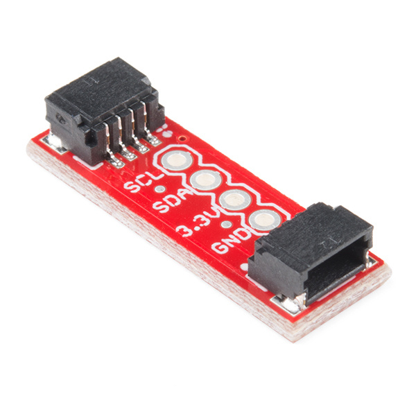
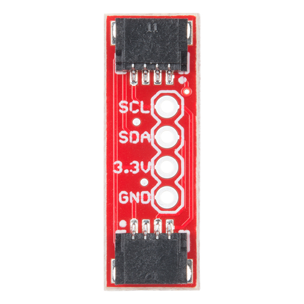
The SparkFun Qwiic adapter board is the perfect board to use if you need to make any old I2C board into a Qwiic enabled board. This adapter breaks out the I2C pins from the Qwiic connectors to pins that you can easily solder with your favorite I2C enabled device.
Suggested Materials
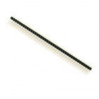
To follow along with this tutorial, you will need a I2C enabled device and some headers:
You will also need our handy Qwiic connectors to easily connect the adapter to your development board or system. Below are a few options:
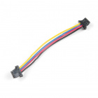
Qwiic Cable - 100mm
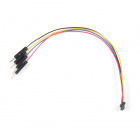
PRT-14427Qwiic Cable - Breadboard Jumper (4-pin)
PRT-14425Qwiic Cable - 50mm
PRT-14426Qwiic Cable - 500mm
PRT-14429Tools
You will need a soldering iron, solder, and general soldering accessories. To modify the headers, you will also need needle nose pliers and diagonal cutters.
Hakko FX888D Soldering Station
TOL-11704Suggested Reading
If you aren't familiar with the Qwiic system, we recommend reading here for an overview.
 |
| Qwiic Connect System |
We would also recommend taking a look at the following tutorials if you aren't familiar with them.
How to Solder: Through-Hole Soldering
Logic Levels
I2C
Hardware Overview
There are a few things you should know about the Qwiic system before you go plugging in I2C devices willy nilly. The first thing to be aware of is that all Qwiic devices run on 3.3V. So if you have a 5V device and you are not using a stackable breakout board with a logic level converter (such as the Qwiic Shield for Arduino), you'll need to grab a logic level converter to boost your signals up to 5V. Also, be aware that all Qwiic devices have pull-up resistors on the I2C lines. So if your device does not have it, you'll need to add those in or use the ones on your microcontroller.
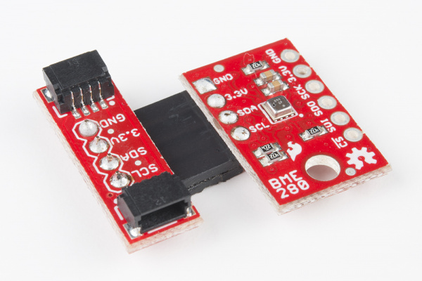
The Qwiic adapter is populated with two 4-pin 1mm JST connectors to quickly connect your I2C devices together. Four plated through holes are broken out for SCL, SDA, 3.3V, and GND. These pins can be used to convert an old I2C enabled device into a Qwiic enabled board.
Hardware Assembly
There are several different ways to connect your I2C device to the Qwiic adapter. The simplest and probably cleanest method would be to use headers. This also allows the adapter to be reattached to a different I2C device in the future. I've found that I enjoy the look of the 90 degree male headers on the Qwiic Adapter, combined with a 90-degree bend in the legs on the female headers I2C device. However, you can really use any combination you'd like depending on how you want the adapter to be oriented relative to your I2C enabled board.
Using pliers, snap off a row of 4 pins from the right angle male header. Using diagonal cutters, you will need to sacrifice one socket in order cut off a row of 4 pins from the female header. Carefully bend the female header's pins using the pliers to make a right angle with the I2C device. Solder the male headers to the Qwiic adapter and the female headers to the I2C device as shown in the image below.
Once you've got headers soldered onto each of your boards, simply plug your adapter into your I2C enabled device. Using a Qwiic cable, plug your Qwiic adapter into a stackable Qwiic board of your choice. Assuming that there is example code loaded on your development board, you can now start reading data from your I2C enabled device!
Resources and Going Further
For more information, check out the resources below:
Now that you have your Qwiic adapter ready to go, it's time to check out some Qwiic enabled products.
More I2C Please
Here is the list of the boards that have the standard I2C pinout and will work with the Qwiic adapter board:
- 9DoF Stick IMU - LSM9DS1
- 9DoF IMU - MPU-9250
- 6DoF IMU - LSM303C
- 6DoF IMU - LSM6DS3
- Triple Axis Accelerometer - LIS3DH
- Triple Axis Magnetometer - MAG3110
- Triple Axis Magnetometer - MLX90393
- Compass Module - HMC6343
- Atmospheric Sensor - BME280
- Barometric Pressure Sensor - MS5803-14BA
- Barometric Pressure Sensor - T5403
- Humidity and Temperature Sensor - Si7021
- Digital Temperature Sensor - TMP102
- Particle Sensor - MAX30105
- Air Quality Sensor - CCS811
- ToF Range Finder - VL6180
- Haptic Motor Driver - DRV2605L
- Micro OLED Display
- RGB and Gesture Sensor - APDS-9960
- RGB Light Sensor - ISL29125
- LED Driver - LP55231
- DAC Breakout - MCP4725
- 16 Output I/O Expander - SX1509
- Battery Babysitter - BQ24075
