Qwiic Digital Desk Sign with MicroMod
 bboyho
Hardware Assembly
If you have not already, make sure to check out the Getting Started with MicroMod: Hardware Hookup for information on inserting your Processor Board to your Carrier Board.
Getting Started with MicroMod
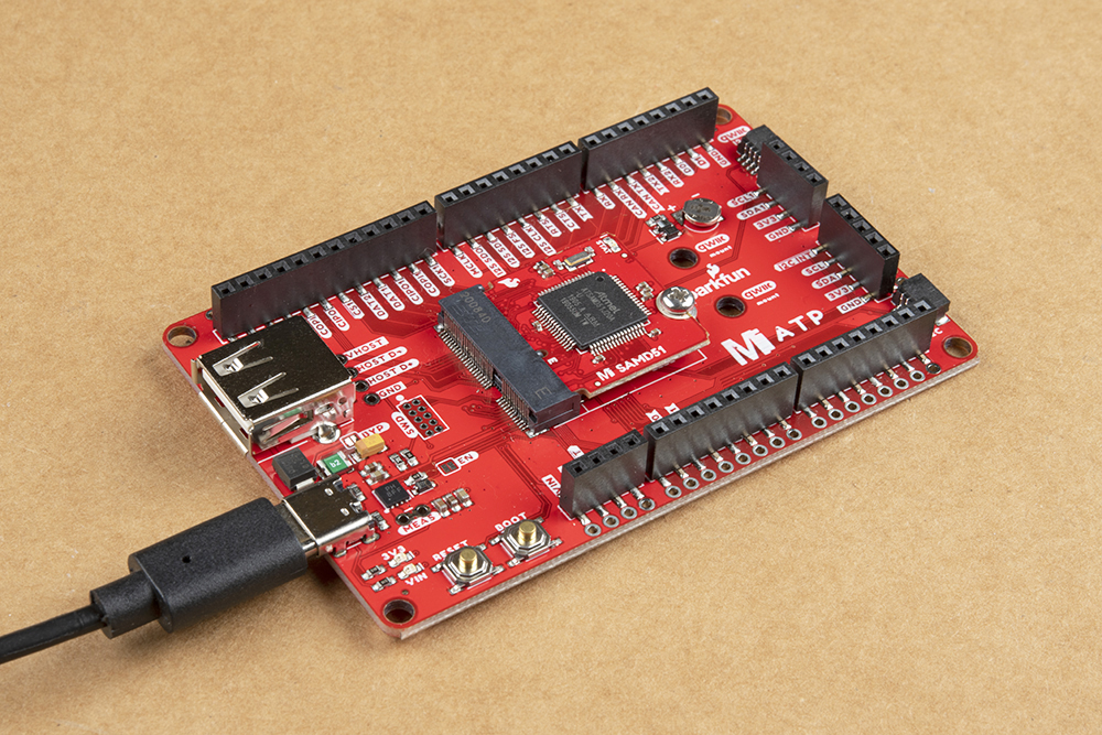
Your board should look like the image below after connecting the MicroMod SAMD51 Processor Board to the MicroMod ATP. To program, insert the USB-C cable.
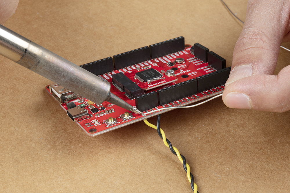
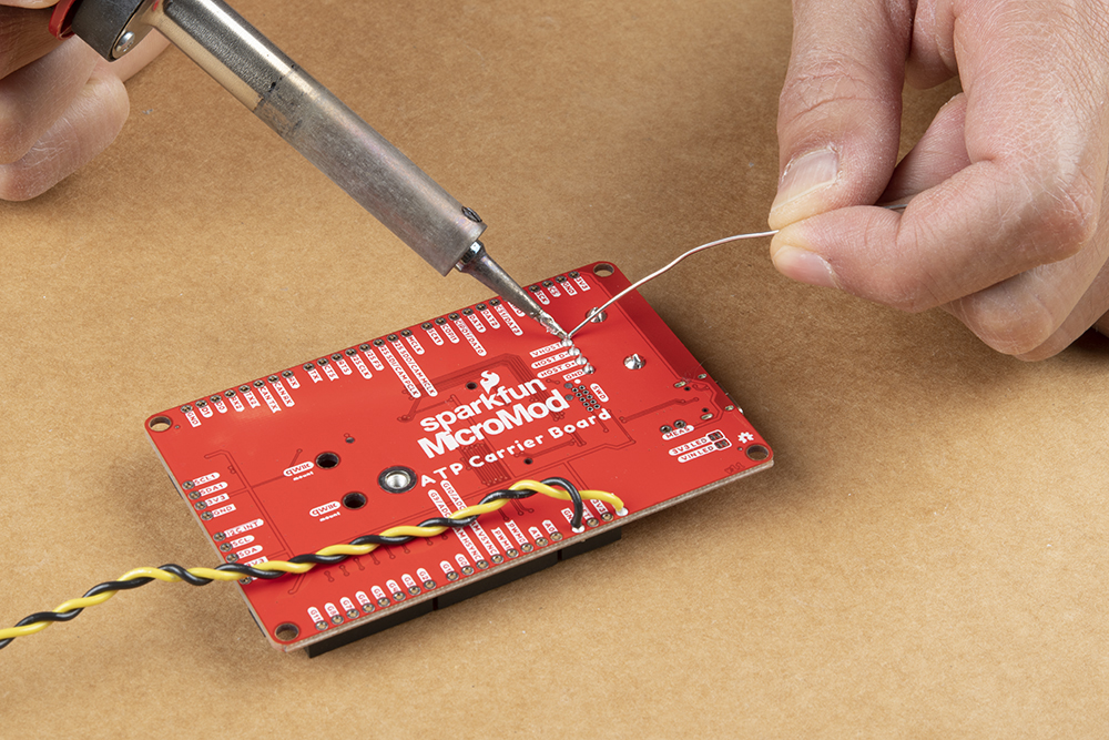
Since the SAMD51 uses the USB connector for USB host, we'll strip and solder wires to the board to connect an external 5V wall adapter.
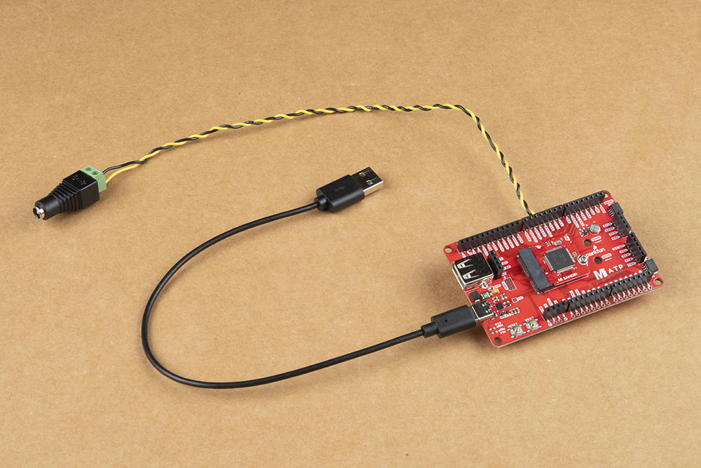
Then we'll strip the other end of the wires and insert them into a female barrel jack adapters with "+" to VIN and "−" to GND. We'll secure the wires by twisting them together.
Due to the design of the MicroMod SAMD51's host pins, we'll need to solder another USB Type A connector breakout to the ATP's host pins using male headers. If you have an adapter to convert the USB Type C to Type A, you can also use that as well.
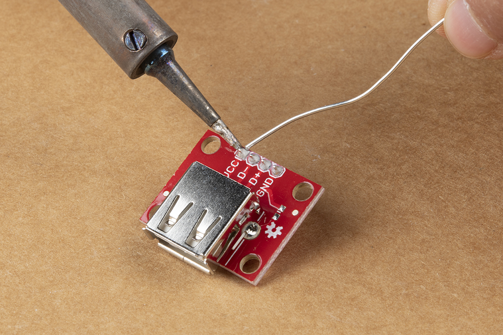
While I could solder the breakout directly to the ATP's host pins, I decided to solder female headers to the board to be able to easily disconnect the USB keyboard.
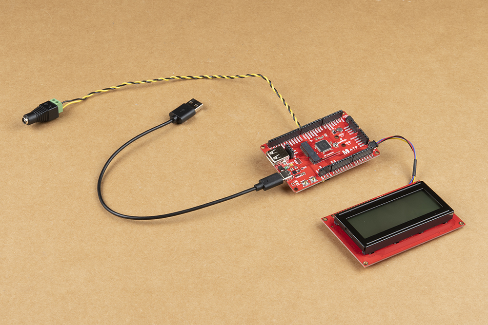
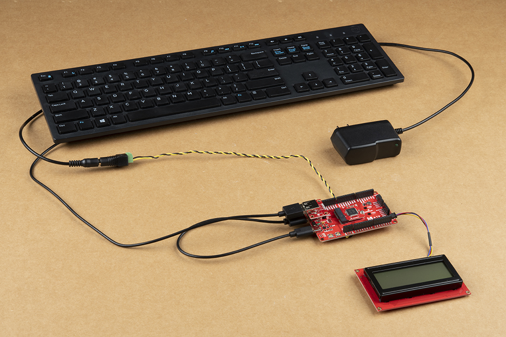
Add a Qwiic cable between the Qwiic SerLCD and MicroMod's Qwiic connector labeled as I2C
Insert a keyboard to the USB breakout board.
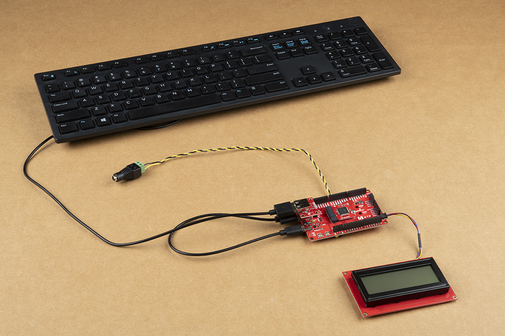
When you have finished programming the SAMD51, you can insert a 5V wall adapter for power.
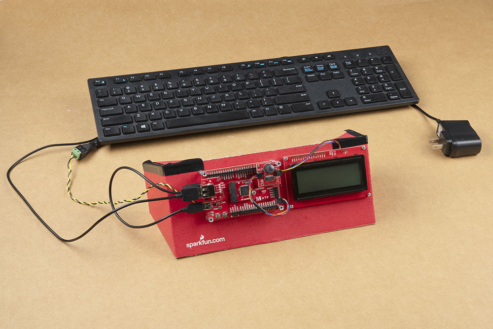
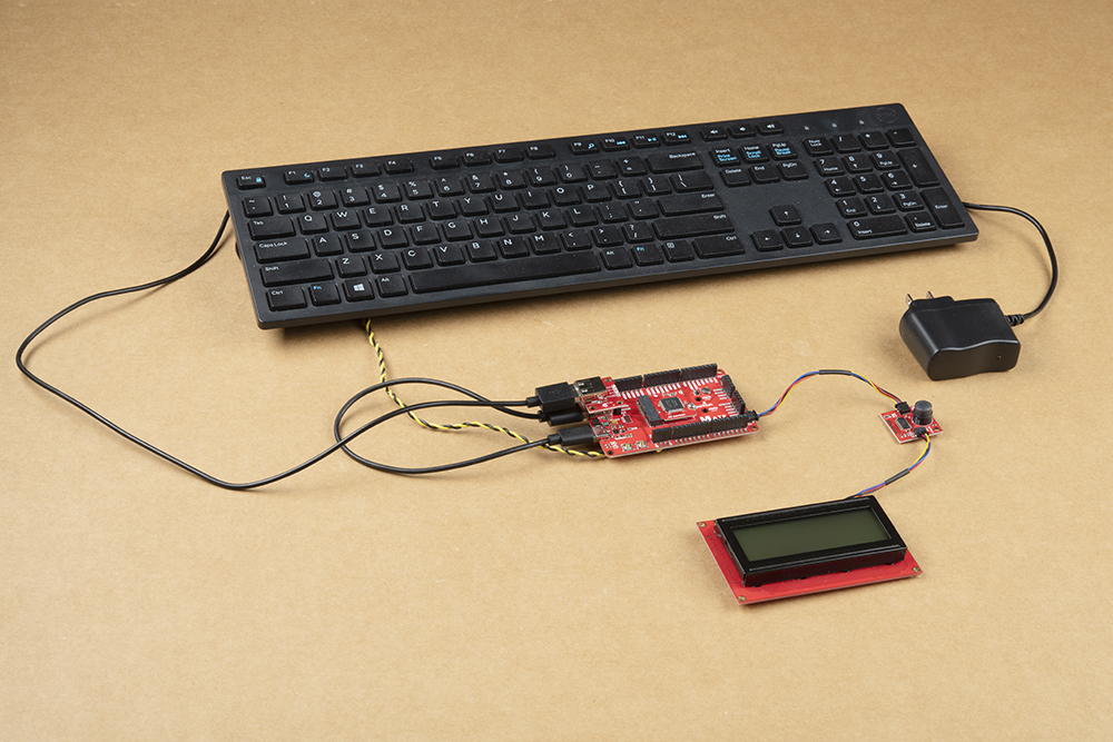
To save power and the screen, you can also add a PIR motion sensor or distance sensor to toggle the screen on and off. An additional Qwiic cable and Qwiic PIR motion sensor was added between the MicroMod ATP and Qwiic SerLCD.
The 20x40 SerLCD was hard to see any messages with it flat on a table so a panel was eventually cut out from a SparkFun cardboard box to mount the project. for the scope of this tutorial, won't go over the specifics of cutting the cardboard in this tutorial or mounting the electronics to the panel.