nRF52832 Breakout Board Hookup Guide
 jimblom
Hardware Overview
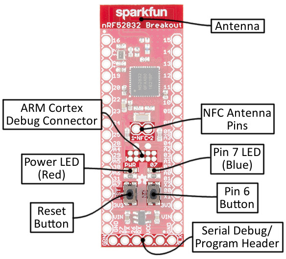
Nordic's nRF52832 is a system-on-chip (SoC) that combines an ARM Cortex-M4F microprocessor with a 2.4GHz multiprotocol radio. In addition to providing access to all of the chip's I/O pins, the breakout board also includes a handful of external components. The annotated image below summarizes the breakout board's features:
Powering the nRF52832 Breakout Board
The nRF52832 can operate on a power supply between 1.7 and 3.6V. The board also includes a 3.3V regulator with a maximum input of 6V, in case you want to power the board with batteries or a regulated wall supply.
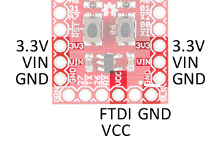
The power input pins are located toward the bottom side of the board. Each of the header rows includes a "GND", "VIN" and "3.3V" supply input. The "VCC" and "GND" pins on the 6-pin serial header can also be used to power the board (assuming the jumper is closed, more on that later).
The VIN pin feeds into the on-board regulator, which brings the voltage down to 3.3V to supply the nRF52832. The regulator can supply up to 600mA -- way more than the nRF52832 should ever need. If you're powering via regulator, you can use the 3.3V pins as outputs to supply external components.
Alternatively, you can skip the regulator and supply the nRF52832 directly by using the 3.3V pin. Voltage supplied here doesn't necessarily have to be 3.3V -- it can be anywhere between the SoC's 1.7V and 3.6V operating range -- so you can use a coin cell battery, or a pair of alkaline batteries to power the chip.
The red power LED is tied to that "3.3V" bus as well. If it's lighting up, your nRF52832 should be getting power.
32 Multipurpose I/O Pins
The nrF52832's microprocessor features an array of hardware peripherals, including three SPI -- configurable as either master or slave, two I2C interfaces, and a UART (with optional flow control). On top of the serial interfaces, the chip also features 8 ADC pins and three hardware PWM outputs. Each of the 32 I/O pins can be assigned almost any function, so you can move those interfaces around the board as you see fit.
Serial Communication
Serial Peripheral Interface (SPI)
Analog to Digital Conversion
I2C
There are just a few functions that are assigned static pins:
- For your real-time counting (RTC) needs, a 32.768kHz crystal is connected to pins 0 and 1.
- Pin 6 is connected to a momentary push-button, which serves an important function during bootloading.
- Pin 7 is tied to an LED. It's active-low, so pull the pin to ground to turn the LED on.
- Pins 26 and 27 were chosen as the RX and TX UART pins. They can be re-assigned in a user-application but are stuck as the serial pins during the bootloader's operation.
- Pin 21 also doubles as an active-low reset input.
- The nRF52832's NFC capability can be supported by an antenna connected to pins 9 and 10.
Setting the Solder Jumpers
The back side of the nRF52832 Breakout is filled with jumpers to help you customize the operation of your board. They're labeled with an abbreviation of their purpose.
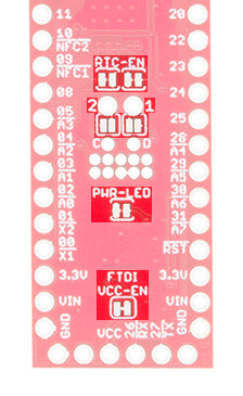
The jumpers that default closed can be sliced open with a hobby knife, while those jumpers that default open can be closed with a small application of solder.
| Jumper Label | Default | Notes |
|---|---|---|
| FTDI VCC-EN | Closed | Connects 6-pin serial header VCC to 3.3V bus. |
| PWR-LED | Closed | Enables or disables the red power indicator LED. |
| 1/2 (NFC) | Open | Connects GPIO 9 and 10 to NFC antenna tuning capacitors. |
| RTC-EN | Closed | Connects GPIO 0 and 1 to a 32.768kHz RTC crystal. |
FTDI VCC-EN - Power via 6-Pin Serial Connector
This jumper controls whether or not an FTDI Breakout connected via the 6-pin serial connector can supply power to the nRF52832. By keeping this jumper to closed, you'll be able to power the nRF52832 with the same device used to program it.
You may want to cut the jumper if you're powering the board externally. Also consider opening the jumper if you're using a 3.3V FTDI Basic (the non-"beefy" version), which may not be able to source enough sustained power to supply the chip.
PWR-LED - Turn Off the Power LED
One of the nRF52832's most important features is its low-power capability. If your application needs to run for months on a single battery and you're making full-use of the nRF52832's ultra-low power sleep modes, the 1-2mA of current pulled by the LED may relatively dwarf the current draw of the microcontroller.
Cutting this jumper will effectively disable the power LED. You won't always have a visible power indicator, but you'll be able to save a lot of power!
1 & 2 - NFC Antenna Tuning Capacitors
One of the most unique features of the nRF52832 is its NFC tag support -- it can transmit data to a nearby NFC-compatible device, or even be programmed to wake-from-sleep in the presence of an NFC field.
To use the NFC feature, a 13.56 MHz antenna must be connected to GPIO pins 9 and 10. Most NFC antennae also require a pair of tuning capacitors between the antenna pins and ground. The NFC jumpers can be closed to connect each of the NFC antenna pins to a 180pF capacitor.
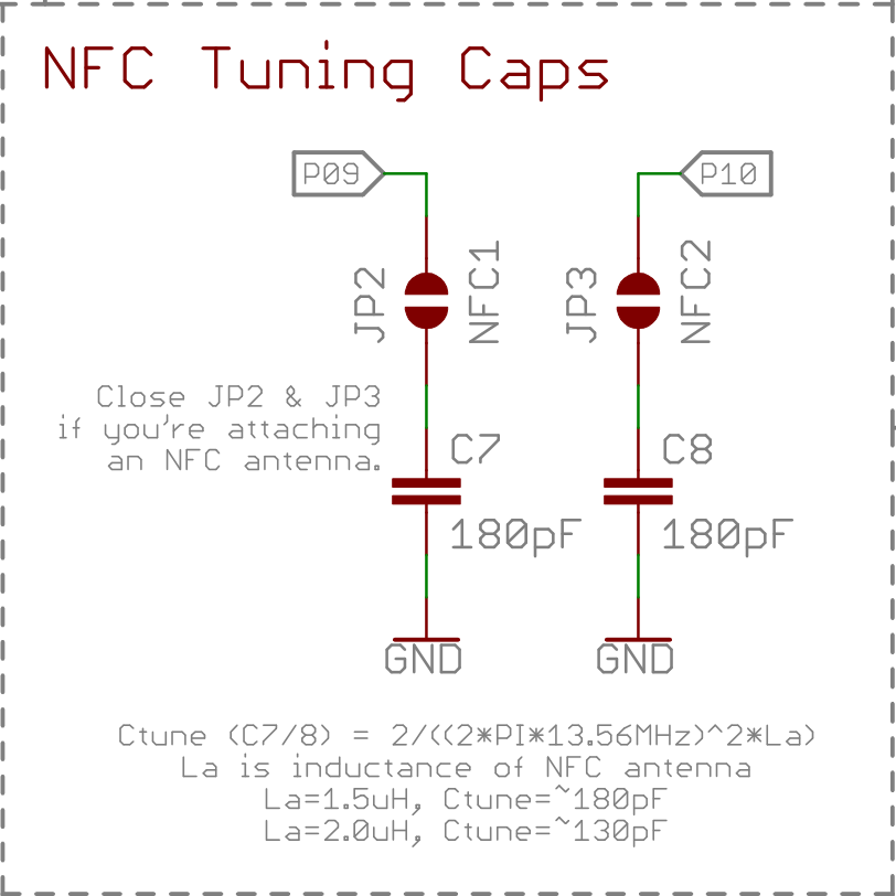
This cap value may not be perfect for every antenna, but it should support a relatively wide range of antenna inductances. We tested it successfully with an Abracon ANFACA-4545-A01 and a Pulse Electronics W7001.
RTC-EN - Connect/Disconnect the 32.768kHz Crystal
The nRF52832 Breakout equips the chip with a 32.768kHz crystal -- connected to GPIO pins 0 and 1. Unfortunately, those pins make up a quarter of the available ADC inputs. So, if your application doesn't require an RTC -- and you need those pins to for another purpose -- grab a hobby knife and cut the two traces between their pads to disconnect the crystal.