nRF52832 Breakout Board Hookup Guide
 jimblom
 Introduction
The nRF52832 is Nordic Semiconductor's latest multiprotocol radio system-on-chip (SoC). It's half microcontroller, with a list of features including 32 configurable I/O pins, SPI, I2C, UART, PWM, ADC's, 512kB flash, and 64kB RAM. And, it's half 2.4GHz multiprotocol radio, supporting Bluetooth low energy (BLE), ANT, and Nordic's proprietary 2.4GHz ultra low-power wireless communication -- it even features on-chip NFC tag support.
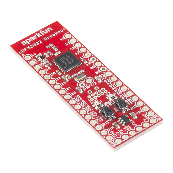
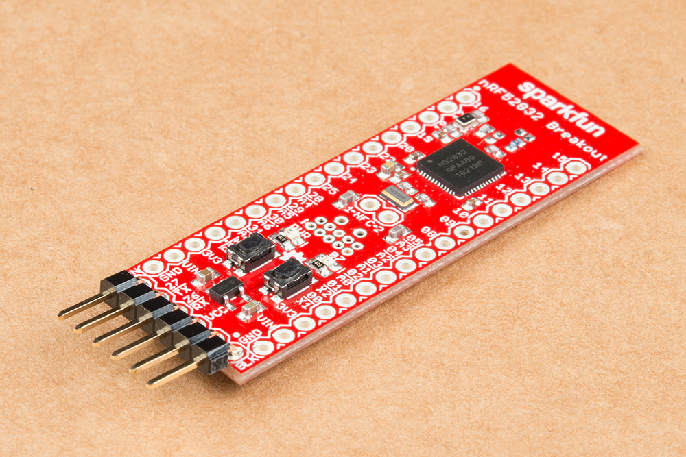
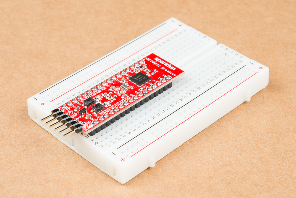
SparkFun nRF52832 Breakout
WRL-13990SparkFun's nRF52832 Breakout provides easy access to all of the chip's features. It breaks out all of the nRF52's I/O pins, provides a 32.768kHz RTC crystal, a user-programmable button and LED, and a trace antenna to send and receive those 2.4GHz transmissions. Plus, to make the chip as easy-to-flash as possible, the breakout comes pre-programmed with a serial bootloader.
Covered In This Tutorial
This tutorial is a comprehensive getting started guide for the SparkFun nRF52832 Breakout. It documents hardware features of the board, and includes tips on getting a computer set up for nRF52832 software development. Programming the chip via the serial bootloader using the Arduino IDE is the primary focus of the latter half of the tutorial.
Bill of Materials
To follow along with this tutorial -- and to get your nRF52832 Breakout up-and-running -- you'll need a few additional components.
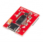
To program the board, we recommend interfacing the breakout board with a SparkFun Beefy 3 - FTDI Basic Breakout. In addition to providing a USB-to-serial programming interface, this board will also be able to fully-power the nRF52832 breakout. The less-beefy 3.3V FTDI Basic can also be used to program the board, but we recommend finding an alternative power supply to power the nRF52832 board. Whichever USB-to-serial converter you go with, don't forget the USB cable!

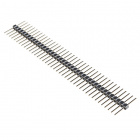
To interface the nRF52832 Breakout with the FTDI, you'll need to solder a 6-pin strip of headers to the board's serial interface. We recommend right-angle headers for this job, but the straight or long headers can also get it done. Grab some extra male headers -- or even female headers -- if you plan on connecting to any of the I/O pins.


Finally, to complete the Bluetooth connection, you'll need a BLE-equipped smartphone. This tutorial documents how to use the nRF52832 with Nordic's free, open-source nRF Toolbox and nRF Connect apps, which are available on both iOS and Android devices.
|
 |
Suggested Reading
The nRF52832 Breakout is an intermediate-to-advanced level board, but don't let that scare you off! This tutorial should be able to walk you through getting started with the board regardless of your skill level. That said, we do recommend that you're familiar with the topics covered in these tutorials:
Serial Communication
Using the Arduino Pro Mini 3.3V
Bluetooth Basics
SparkFun USB to Serial UART Boards Hookup Guide
Hardware Overview
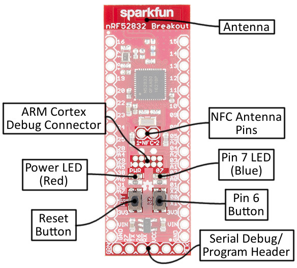
Nordic's nRF52832 is a system-on-chip (SoC) that combines an ARM Cortex-M4F microprocessor with a 2.4GHz multiprotocol radio. In addition to providing access to all of the chip's I/O pins, the breakout board also includes a handful of external components. The annotated image below summarizes the breakout board's features:
Powering the nRF52832 Breakout Board
The nRF52832 can operate on a power supply between 1.7 and 3.6V. The board also includes a 3.3V regulator with a maximum input of 6V, in case you want to power the board with batteries or a regulated wall supply.
The power input pins are located toward the bottom side of the board. Each of the header rows includes a "GND", "VIN" and "3.3V" supply input. The "VCC" and "GND" pins on the 6-pin serial header can also be used to power the board (assuming the jumper is closed, more on that later).
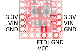
The VIN pin feeds into the on-board regulator, which brings the voltage down to 3.3V to supply the nRF52832. The regulator can supply up to 600mA -- way more than the nRF52832 should ever need. If you're powering via regulator, you can use the 3.3V pins as outputs to supply external components.
Alternatively, you can skip the regulator and supply the nRF52832 directly by using the 3.3V pin. Voltage supplied here doesn't necessarily have to be 3.3V -- it can be anywhere between the SoC's 1.7V and 3.6V operating range -- so you can use a coin cell battery, or a pair of alkaline batteries to power the chip.
The red power LED is tied to that "3.3V" bus as well. If it's lighting up, your nRF52832 should be getting power.
32 Multipurpose I/O Pins
The nrF52832's microprocessor features an array of hardware peripherals, including three SPI -- configurable as either master or slave, two I2C interfaces, and a UART (with optional flow control). On top of the serial interfaces, the chip also features 8 ADC pins and three hardware PWM outputs. Each of the 32 I/O pins can be assigned almost any function, so you can move those interfaces around the board as you see fit.
Serial Communication
Serial Peripheral Interface (SPI)
Analog to Digital Conversion
I2C
There are just a few functions that are assigned static pins:
- For your real-time counting (RTC) needs, a 32.768kHz crystal is connected to pins 0 and 1.
- Pin 6 is connected to a momentary push-button, which serves an important function during bootloading.
- Pin 7 is tied to an LED. It's active-low, so pull the pin to ground to turn the LED on.
- Pins 26 and 27 were chosen as the RX and TX UART pins. They can be re-assigned in a user-application but are stuck as the serial pins during the bootloader's operation.
- Pin 21 also doubles as an active-low reset input.
- The nRF52832's NFC capability can be supported by an antenna connected to pins 9 and 10.
Setting the Solder Jumpers
The back side of the nRF52832 Breakout is filled with jumpers to help you customize the operation of your board. They're labeled with an abbreviation of their purpose.
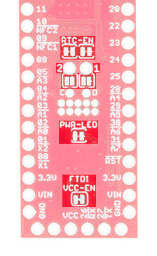
The jumpers that default closed can be sliced open with a hobby knife, while those jumpers that default open can be closed with a small application of solder.
| Jumper Label | Default | Notes |
|---|---|---|
| FTDI VCC-EN | Closed | Connects 6-pin serial header VCC to 3.3V bus. |
| PWR-LED | Closed | Enables or disables the red power indicator LED. |
| 1/2 (NFC) | Open | Connects GPIO 9 and 10 to NFC antenna tuning capacitors. |
| RTC-EN | Closed | Connects GPIO 0 and 1 to a 32.768kHz RTC crystal. |
FTDI VCC-EN - Power via 6-Pin Serial Connector
This jumper controls whether or not an FTDI Breakout connected via the 6-pin serial connector can supply power to the nRF52832. By keeping this jumper to closed, you'll be able to power the nRF52832 with the same device used to program it.
You may want to cut the jumper if you're powering the board externally. Also consider opening the jumper if you're using a 3.3V FTDI Basic (the non-"beefy" version), which may not be able to source enough sustained power to supply the chip.
PWR-LED - Turn Off the Power LED
One of the nRF52832's most important features is its low-power capability. If your application needs to run for months on a single battery and you're making full-use of the nRF52832's ultra-low power sleep modes, the 1-2mA of current pulled by the LED may relatively dwarf the current draw of the microcontroller.
Cutting this jumper will effectively disable the power LED. You won't always have a visible power indicator, but you'll be able to save a lot of power!
1 & 2 - NFC Antenna Tuning Capacitors
One of the most unique features of the nRF52832 is its NFC tag support -- it can transmit data to a nearby NFC-compatible device, or even be programmed to wake-from-sleep in the presence of an NFC field.
To use the NFC feature, a 13.56 MHz antenna must be connected to GPIO pins 9 and 10. Most NFC antennae also require a pair of tuning capacitors between the antenna pins and ground. The NFC jumpers can be closed to connect each of the NFC antenna pins to a 180pF capacitor.
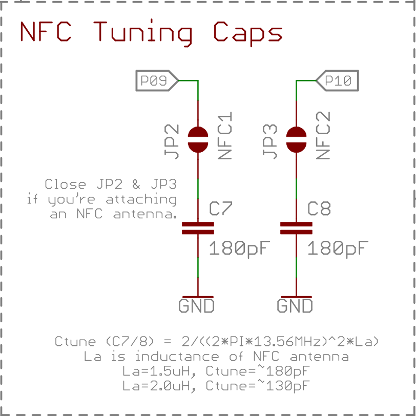
This cap value may not be perfect for every antenna, but it should support a relatively wide range of antenna inductances. We tested it successfully with an Abracon ANFACA-4545-A01 and a Pulse Electronics W7001.
RTC-EN - Connect/Disconnect the 32.768kHz Crystal
The nRF52832 Breakout equips the chip with a 32.768kHz crystal -- connected to GPIO pins 0 and 1. Unfortunately, those pins make up a quarter of the available ADC inputs. So, if your application doesn't require an RTC -- and you need those pins to for another purpose -- grab a hobby knife and cut the two traces between their pads to disconnect the crystal.
Hardware Assembly
To program the chip, and to use any of the nRF52832's 32 I/O, you'll need to solder something to its headers. In the least, we recommend soldering right-angle male headers or straight male headers onto the six-pin serial header. Either of these will interface easily with the FTDI Basic and Beefy Breakouts.
The remaining two rows of vias are breadboard-compatible, so you can solder male pins into both and have it straddle a breadboard.
Or you can solder wire, female headers, or anything else your project requires into those remaining holes.
Adding Arduino Compatibility
Arduino isn't the most powerful IDE out there, nor is it the most versatile, but it does make things easy if you're just getting started with a new platform. Fortunately, there's an nRF52 Arduino board addon available for just that purpose! This section details how to install the nRF52 Arduino libraries, cores, and tools.
Download and Install the Board Package
The nRF52 Arduino cores are based on the great work by sandeepmistry. We've added nRF52832 Breakout Board compatibility to his board files, and added an extra tool to enable serial bootloading.
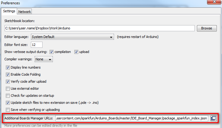
To install support for the nRF52 board in Arduino, begin by opening your Arduino preferences (File > Preferences). Then copy and paste the URL below into the "Additional Board Manager URLs" text box.
https://raw.githubusercontent.com/sparkfun/Arduino_Boards/nrf5/IDE_Board_Manager/package_sparkfun_index.json
Then hit OK, and navigate to the Tools > Board > Boards Manager... tool. A search for "nRF52" should turn up a SparkFun nRF52 Boards result. Select that and click install.
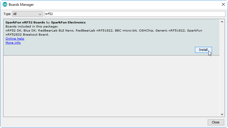
The install may take a few minutes -- the package includes arm-gcc and a few other tools totaling around 100 MB. Once the installation is complete, go to Tools > Board and select "SparkFun nRF52832 Breakout" under the "Nordic Semiconductor nRF5 Boards" section.

Programming via Bootloader
The nRF52832 Breakout ships out with a pre-programmed serial bootloader, so you don't need a specialized JTAG programmer to load code onto it. You do, however, need an FTDI Basic (or an FTDI Basic -like device) to set up a serial interface between your computer and the breakout.
Connecting the FTDI to the Breakout
The FTDI Basic mates up with the nRF52832's 6-pin serial header. Match up the "BLK" and "GRN" labels, and slide the boards together.
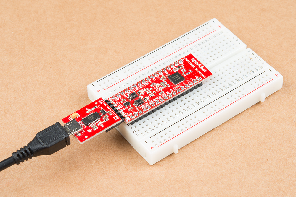
You should see the red power LED illuminate. If it doesn't power up, make sure you haven't disabled the FTDI-VCC EN jumper on the back of the board.
Triggering the Bootloader
Unfortunately, the nRF52832 Breakout's bootloader doesn't feature an auto-reset function like many Arduino's. To decide whether to enter the bootloader or run its application code, the nRF52832 samples the state of GPIO 6 when it boots up. If pin 6 is LOW, it enters the bootloader, otherwise it boots into its programmed application
So, to boot the nRF52832 into its bootloader you must reset the chip while holding down the pin 6 button. In step-by-step form, the trick to resetting into the bootloader is:
- Press down on both the RESET and 06 buttons.
- Release reset.
- Verify that the blue (pin 7) LED begins blinking.
- Release the 06-labeled user button.
While in bootloader mode, the nRF52832's blue LED on pin 7 should blink at increasing speed in what we call the "timebomb" sequence.
This is, admittedly, a little tricky and a lot annoying to perform before every program, but it's the trade-off we get for not programming via expensive JTAG programmers. Once you've entered the bootloader, you can upload code to the chip via Arduino's "Upload" button.
Upload Blink
Try loading up a basic blink example -- setting the blinking pin to the on-board LED on pin 7 -- and uploading. Here's some code to copy paste:
language:c
const int ledPin = 7;

void setup()
{
    pinMode(ledPin, OUTPUT);
}

void loop()
{
    digitalWrite(ledPin, HIGH);
    delay(500);
    digitalWrite(ledPin, LOW);
    delay(500);
}
Troubleshooting
If you get an upload error like this:
Failed to upgrade target. Error is: No data received on serial port. Not able to proceed.
Possible causes:
- bootloader, SoftDevice or application on target does not match the requirements in the DFU package.
- baud rate or flow control is not the same as in the target bootloader.
- target is not in DFU mode. If using the SDK examples, press Button 4 and RESET and release both to enter DFU mode.
Make sure your nRF52832 Breakout's LED is blinking in a ticking-timebomb pattern -- ensuring that it's in bootloader mode. If the chip is in the bootloader and still not accepting code, try cycling power to the breakout by disconnecting and reconnecting the FTDI Basic.
BLEPeripheral Arduino Library
The nRF5 board definitions will allow you to program the nRF52832 and toggle its GPIO, but it doesn't include any Bluetooth support. For that, we recommend grabbing the BLEPeripheral Arduino library.
The BLEPeripheral library can be installed from Arduino's Library Manager. Simply go to Sketch > Include Library > Manage Libraries.... In the search box, type "BLEPeripheral", select it, and click "Install."

Alternatively, the library can be installed by downloading the latest version from the GitHub repository. Follow along with our Installing an Arduino Library tutorial for help installing the library via this method.
BLE Blink Example
Here are a few examples that show as bare-bones as possible what it takes to turn your nRF52832 Breakout into a BLE peripheral. This first example allows you to control the board's pin 7 LED from your smart phone -- using the nRF Connect app. It's the Blink sketch of the BLE world!
To test the Bluetooth connection, you’ll need to pair the breakout board with another Bluetooth-compatible device. Most modern smartphones can fit that bill.
You'll also need a BLE application installed on your phone – something that lets you connect to devices and fiddle with or read their characteristics. There are a handful of Bluetooth debugging applications out there that can help get you started communicating via Bluetooth. PunchThrough’s LightBlue Explorer is one of our favorite’s, but it’s only available for iOS. Nordic’s nRF Connect – available for both iOS and Android devices – is another good choice. That’s what we’ll document here.
The Code
Copy and paste the code below into your Arduino IDE.
language:c
// Import libraries (BLEPeripheral depends on SPI)
#include <SPI.h>
#include <BLEPeripheral.h>

//////////////
// Hardware //
//////////////
#define LED_PIN    7 // LED on pin 7
#define LED_ACTIVE LOW // Pin 7 LED is active low
#define LED_DEFAULT LOW

///////////////////////
// BLE Advertisments //
///////////////////////
const char * localName = "nRF52832 LED";
BLEPeripheral blePeriph;
BLEService bleServ("1207");
BLECharCharacteristic ledChar("1207", BLERead | BLEWrite);

void setup()
{
  Serial.begin(115200); // Set up serial at 115200 baud

  pinMode(LED_PIN, OUTPUT);
  digitalWrite(LED_PIN, !LED_ACTIVE);

  setupBLE();
}

void loop()
{
  blePeriph.poll();

  if (ledChar.written())
  {
    int ledState = ledChar.value();
    if (ledState)
      digitalWrite(LED_PIN, LED_ACTIVE);
    else
      digitalWrite(LED_PIN, !LED_ACTIVE);
  }
}

void setupBLE()
{
  // Advertise name and service:
  blePeriph.setDeviceName(localName);
  blePeriph.setLocalName(localName);
  blePeriph.setAdvertisedServiceUuid(bleServ.uuid());

  // Add service
  blePeriph.addAttribute(bleServ);

  // Add characteristic
  blePeriph.addAttribute(ledChar);

  // Now that device6, service, characteristic are set up,
  // initialize BLE:
  blePeriph.begin();

  // Set led characteristic to default value:
  ledChar.setValue(!LED_ACTIVE);
}
Then upload the code to your Breakout, using the instructions from the previous section.
Use the nRF Connect to Test
Upon opening nRF Connect, you'll be presented with a list of nearby Bluetooth devices. If you're in the SparkFun offices -- or otherwise surrounded by coworker's with way too many Bluetooth devices -- your list may include page(s) of device names. Look for "nRF52832 LED", and click the "Connect" button next to that. (Note: until you connect to the breakout, it may, instead, advertise the name "Arduino".)
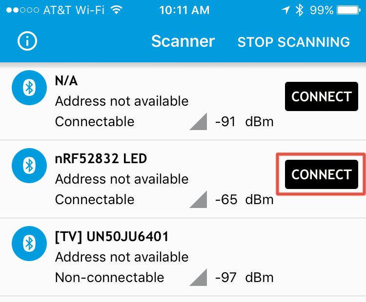
blePeripheral.setDeviceName([name]) function.Click "Connect" on the nRF52832 LED device, and you'll be sent over to the "Services" view. From there, click "Unknown Service" -- the UUID string should match that of the bleServ object in your example code.
This next interface takes some experimenting to figure out. The down arrows represent reads, the up arrows allow you to write to a characteristic, and the triple-down-arrow turns notify on or off. To begin, tap the up arrow next to the top "unknown service". This will allow you to control the state of the LED. In the box that opens up, try entering either 00 or 01, which should turn the LED either off or on, respectively.

After tapping "Send" you should see the LED change state.
BLE Button Example
This example demonstrates how to use the BLE read and notify features. It monitors the button on pin 6 of the nRF52832 Breakout. When the button state changes a BLE notification is sent.
The Code
Using the BLEPeripheral library, upload this code to your Breakout:
language:c
// Import libraries (BLEPeripheral depends on SPI)
#include <SPI.h>
#include <BLEPeripheral.h>

//////////////
// Hardware //
//////////////
#define BTN_PIN    6 // BTN pin on 6
#define BTN_ACTIVE LOW

///////////////////////
// BLE Advertisments //
///////////////////////
const char * localName = "nRF52832 Button";
BLEPeripheral blePeriph;
BLEService bleServ("1234");
BLECharCharacteristic btnChar("1234", BLERead | BLENotify);

void setup()
{
  Serial.begin(115200); // Set up serial at 115200 baud

  pinMode(BTN_PIN, INPUT_PULLUP);
  digitalWrite(7, HIGH);

  setupBLE();
}

void loop()
{
  blePeriph.poll();

  // read the current button pin state
  char buttonValue = digitalRead(BTN_PIN);

  // has the value changed since the last read
  bool buttonChanged = (btnChar.value() != buttonValue);

  if (buttonChanged)
  {
    // button state changed, update characteristics
    btnChar.setValue(buttonValue);
  }
}

void setupBLE()
{
  // Advertise name and service:
  blePeriph.setDeviceName(localName);
  blePeriph.setLocalName(localName);
  blePeriph.setAdvertisedServiceUuid(bleServ.uuid());

  // Add service
  blePeriph.addAttribute(bleServ);

  // Add characteristic
  blePeriph.addAttribute(btnChar);

  // Now that device, service, characteristic are set up,
  // initialize BLE:
  blePeriph.begin();
}
Use the nRF Connect to Test
Use nRF Connect to connect to your nRF52832 Breakout -- just like last time. This time the name of the device should change to nRF52832 Button (if it's still "LED", try connecting anyway -- sometimes the local ID doesn't change until you've connected to it).
Tap into the "Unknown Service" again, but, this time, try tapping the single-down arrow to read the service's characteristic. This will read the state of the nRF52832 Breakout's pin 6 button. While the button is un-actuated, the value of the property should be 0x01. If you can hold the button down while also tapping the single-down arrow, the value should change to 0x00.
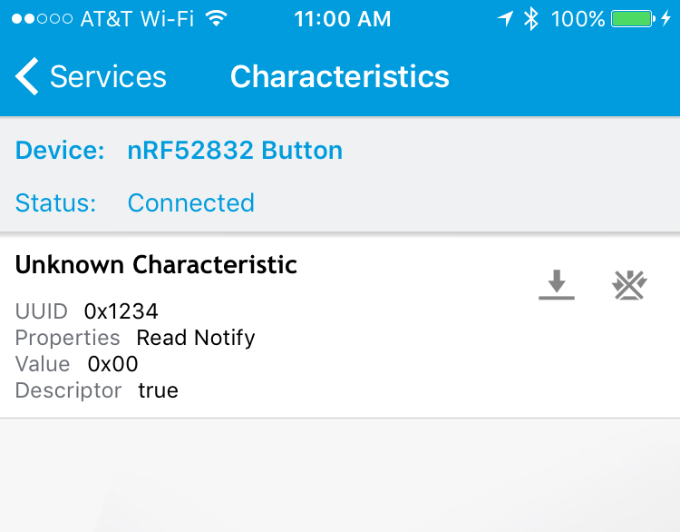
You can also try setting the characteristic to notify, by tapping the triple-down arrow. In this mode, the value should automatically be notified when there's a change in state. Press and release the button to see the value change from 0x00 to 0x01.
Resources and Going Further
There are loads of resources available to you as you continue on in your nRF52832 development.
Hardware Resources
The nRF52832 Breakout is open-source hardware. Feel free to browse our EAGLE design files, download schematics and follow the products lifecycle on our GitHub repository.
For more on the nRF52832, your first visit should be to the "Documentation" and "Downloads" tabs of Nordic's nRF52832 Product Page. There you'll find loads of datasheets, user manuals, and software tools.
Programming w/ the nRF52832 Hardware Development Kit
If you feel hamstrung by the bootloader and want to begin JTAG'ing and debugging the nRF52832 with a more robust tool, consider grabbing the nRF52832 Hardware Development Kit. You can even use it to program the nRF52832 via the SWD protocol.
Locate the SWD header on the nRF52832 Hardware Development Kit and SWD pins for the nRF52832 breakout board.
| nRF52832 Hardware Development Kit SWD Pins | nRF52832 Breakout Board SWD Pins |
|---|---|
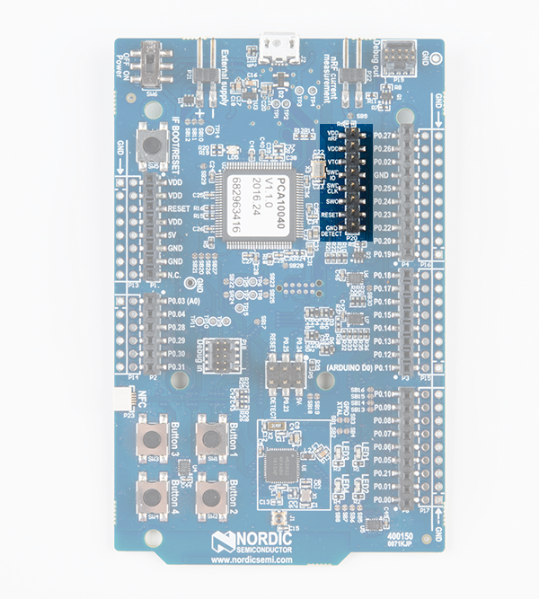 | 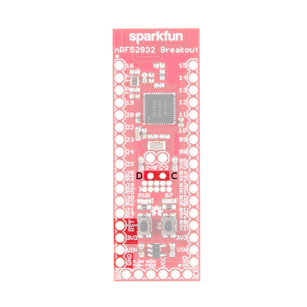 |
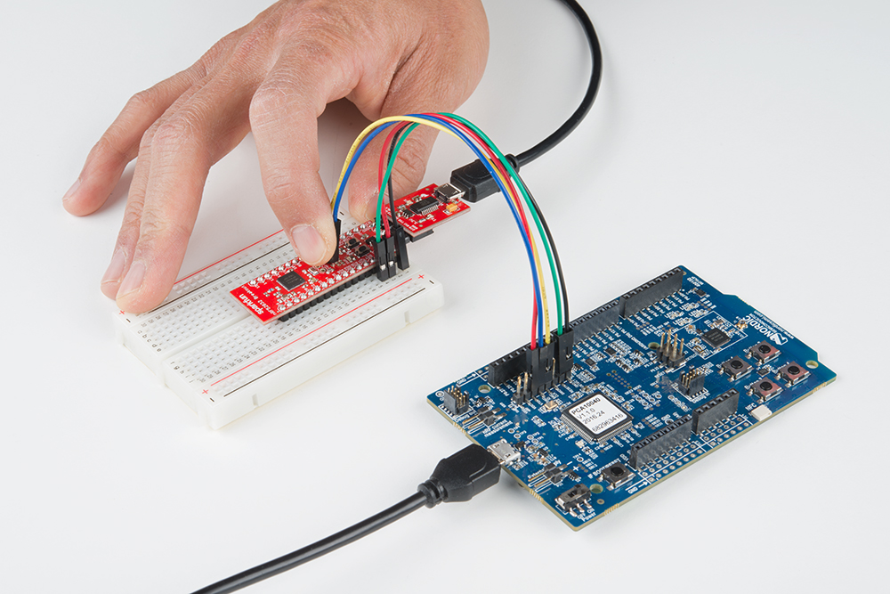
Using 5x M/F premium jumper wires and a breadboard, make the connections listed in the table below. Vdd nRF, VDD, and the SWO do not need to be connected when programming the target nRF52832 breakout board. You can also use the other 3V3 or GND pins located around the nRF52832 breakout board. The nRF52832's single-wire debug -- SWD -- pins are broken out to test points near the NFC antenna pads -- labeled "C" and "D" for SWDCLK and SWDIO, respectively. The SWD test points are not using standard through hole sizes so a standard male break away header will not fit. Cutting a 2-pin header from the female header will fit but can block the some of the 2x5 header.
| nRF52832 Hardware Development Kit | M/F Jumper Wire Color | nRF52832 Breakout Board |
|---|---|---|
| VDD nRF | NC | |
| VDD | NC | |
| VTG | Red | 3.3V |
| SWDIO | Blue | D |
| SWDCLK | Yellow | C |
| SWO | NC | |
| RESET | Green | RST |
| GND | Black | GND |
Add the SparkFun Beefy 3 FTDI to the RF52832 breakout board's FTDI header. Connect a micro-B USB cable nRF52832 Hardware Development Kit and another micro-B cable to the target nRF52832 Breakout Board. While programming the target, make sure the jumper wire pins have contact with pins D and C by lightly pushing the jumper wire pins against the through holes. You could also solder the jumper wire pins for a more secure connection.
Software Resources
The pair of Arduino examples in this tutorial barely scratch the surface of the nRF52832 and the BLEPeripheral library's capabilities. For more on the BLEPeripheral library, we recommend checking out the included examples, under the File > Examples > BLEPeripheral menu in Arduino. When you begin creating BLEPeripheral sketches of your own, we recommend checking out the library's API.
The nRF5 SDK -- Nordic's software development kit for the nRF51 and nRF52 series chips -- is an amazing suite of software and example applications. All you need to set the toolchain up is ARMGCC (the SDK also supports Keil and IAR, if you've already shelled out for those options). The SDK is rife with examples which demonstrate all of the nRF52832's BLE capabilities, plus ANT, NFC, and all of the chip's hardware peripheral features.
For more wireless fun, check out these other great SparkFun tutorials:
Experiment Guide for RedBot with Shadow Chassis
EL Sequencer/Escudo Dos Hookup Guide
ESP32 Thing Plus Hookup Guide
Wireless RC Robot with Arduino and XBees
For more information about using controlling MIDI with the nRF52832 Breakout Board, check out the MIDI BLE tutorial linked to this blog post: