nRF52832 Breakout Board Hookup Guide
 jimblom
Programming via Bootloader
The nRF52832 Breakout ships out with a pre-programmed serial bootloader, so you don't need a specialized JTAG programmer to load code onto it. You do, however, need an FTDI Basic (or an FTDI Basic -like device) to set up a serial interface between your computer and the breakout.
Connecting the FTDI to the Breakout
The FTDI Basic mates up with the nRF52832's 6-pin serial header. Match up the "BLK" and "GRN" labels, and slide the boards together.
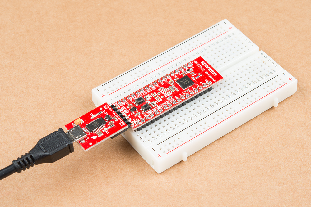
You should see the red power LED illuminate. If it doesn't power up, make sure you haven't disabled the FTDI-VCC EN jumper on the back of the board.
Triggering the Bootloader
Unfortunately, the nRF52832 Breakout's bootloader doesn't feature an auto-reset function like many Arduino's. To decide whether to enter the bootloader or run its application code, the nRF52832 samples the state of GPIO 6 when it boots up. If pin 6 is LOW, it enters the bootloader, otherwise it boots into its programmed application
So, to boot the nRF52832 into its bootloader you must reset the chip while holding down the pin 6 button. In step-by-step form, the trick to resetting into the bootloader is:
- Press down on both the RESET and 06 buttons.
- Release reset.
- Verify that the blue (pin 7) LED begins blinking.
- Release the 06-labeled user button.
While in bootloader mode, the nRF52832's blue LED on pin 7 should blink at increasing speed in what we call the "timebomb" sequence.
This is, admittedly, a little tricky and a lot annoying to perform before every program, but it's the trade-off we get for not programming via expensive JTAG programmers. Once you've entered the bootloader, you can upload code to the chip via Arduino's "Upload" button.
Upload Blink
Try loading up a basic blink example -- setting the blinking pin to the on-board LED on pin 7 -- and uploading. Here's some code to copy paste:
language:c
const int ledPin = 7;

void setup()
{
    pinMode(ledPin, OUTPUT);
}

void loop()
{
    digitalWrite(ledPin, HIGH);
    delay(500);
    digitalWrite(ledPin, LOW);
    delay(500);
}
Troubleshooting
If you get an upload error like this:
Failed to upgrade target. Error is: No data received on serial port. Not able to proceed.
Possible causes:
- bootloader, SoftDevice or application on target does not match the requirements in the DFU package.
- baud rate or flow control is not the same as in the target bootloader.
- target is not in DFU mode. If using the SDK examples, press Button 4 and RESET and release both to enter DFU mode.
Make sure your nRF52832 Breakout's LED is blinking in a ticking-timebomb pattern -- ensuring that it's in bootloader mode. If the chip is in the bootloader and still not accepting code, try cycling power to the breakout by disconnecting and reconnecting the FTDI Basic.